

Page 1
IMPORTANT: Save for local electrical inspector’s use.
INSTALLATION INSTRUCTIONS
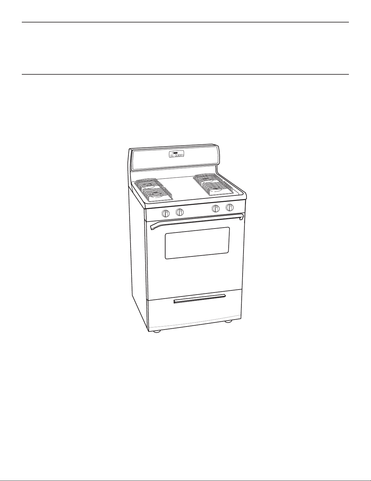
30" (76.2 CM) FREESTANDING GAS RANGE
with standard clean oven
W10032070
Table of Contents..................................................2
Page 2
2
TABLE OF CONTENTS
RANGE SAFETY .......................................................................... 2
INSTALLATION REQUIREMENTS .............................................. 4
Tools and Parts .......................................................................... 4
Location Requirements.............................................................. 4
Electrical Requirements ............................................................ 6
Gas Supply Requirements ........................................................ 6
INSTALLATION INSTRUCTIONS ............................................ 8
Unpack Range ............................................................................8
Install Anti-Tip Bracket ..............................................................8
Verify Anti-Tip Bracket Location ................................................9
Level Range ................................................................................9
Make Gas Connection................................................................9
Check Operation ......................................................................10
Complete Installation ..............................................................11
GAS CONVERSIONS ...............................................................12
LP Gas Conversion ..................................................................12
Complete Conversion ..............................................................13
Natural Gas Conversion. ..........................................................14
Complete Conversion ..............................................................15
RANGE SAFETY
Your safety and the safety of others are very important.
We have provided many important safety messages in this manual and on your appliance. Always read and obey all safety
messages.
This is the safety alert symbol.
This symbol alerts you to potential hazards that can kill or hurt you and others.
All safety messages will follow the safety alert symbol and either the word “DANGER” or “WARNING.”
These words mean:
You can be killed or seriously injured if you don't immediately
DANGER
WARNING
All safety messages will tell you what the potential hazard is, tell you how to reduce the chance of injury, and tell you what can
happen if the instructions are not followed.
follow instructions.
can be killed or seriously injured if you don't
You
instructions.
follow
Page 3

3
WARNING: If the information in this manual is not followed exactly, a fire or explosion
may result causing property damage, personal injury or death.
– Do not store or use gasoline or other flammable vapors and liquids in the vicinity of this
or any other appliance.
– WHAT TO DO IF YOU SMELL GAS:
Do not try to light any appliance.
•
Do not touch any electrical switch.
•
Do not use any phone in your building.
•
Immediately call your gas supplier from a neighbor's phone. Follow the gas supplier's
•
instructions.
If you cannot reach your gas supplier, call the fire department.
•
– Installation and service must be performed by a qualified installer, service agency, or
the gas supplier.
In the State of Massachusetts, the following installation instructions apply:
■ Installations and repairs must be performed by a qualified or licensed contractor, plumber, or gasfitter qualified or licensed by
the State of Massachusetts.
■ If using a ball valve, it shall be a T-handle type.
■ A flexible gas connector, when used, must not exceed 3 feet.
WARNING
Tip Over Hazard
A child or adult can tip the range and be killed.
Connect anti-tip bracket to rear range foot.
Reconnect the anti-tip bracket, if the range is moved.
Failure to follow these instructions can result in death or serious burns to children and adults.
Page 4
4
INSTALLATION REQUIREMENTS
Tools and Parts
Gather the required tools and parts before starting installation.
Read and follow the instructions provided with any tools listed
here.
Tools needed
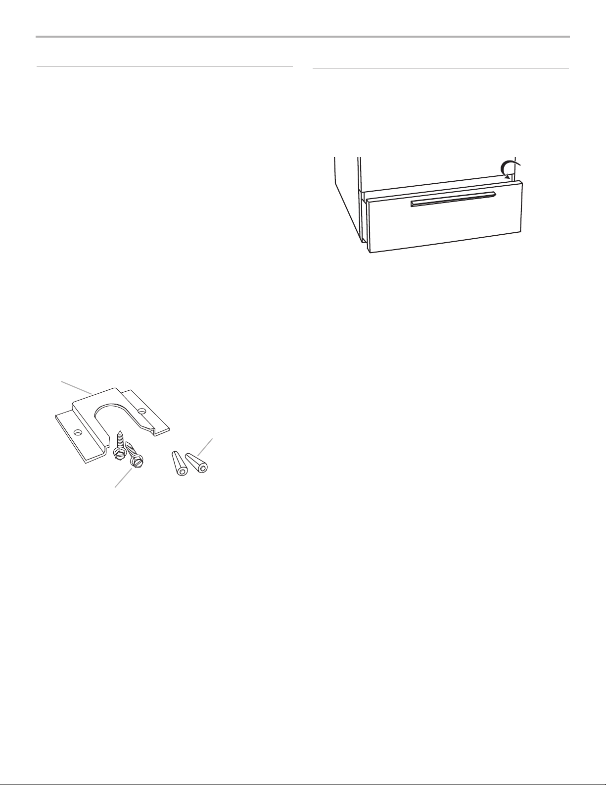
Parts supplied
Check that all parts are included.
■ Anti-tip brackets must be securely mounted to subfloor.
Thickness of flooring may require longer screws to anchor
bracket to subfloor. Longer screws are available from your
local hardware store.
Parts needed
Check local codes and consult gas supplier. Check existing gas
supply and electrical supply. See “Electrical Requirements” and
“Gas Supply Requirements” sections.
Location Requirements
IMPORTANT: Observe all governing codes and ordinances. Do
not obstruct flow of combustion and ventilation air.
■ It is the installer’s responsibility to comply with installation
clearances specified on the model/serial rating plate. The
model/serial rating plate is located on the oven frame behind
the left side of the broiler door.
■ The range should be located for convenient use in the
kitchen.
■ Recessed installations must provide complete enclosure of
the sides and rear of the range.
■ To eliminate the risk of burns or fire by reaching over heated
surface units, cabinet storage space located above the
surface units should be avoided. If cabinet storage is to be
provided, the risk can be reduced by installing a range hood
that projects horizontally a minimum of 5" (12.7 cm) beyond
the bottom of the cabinets.
■ All openings in the wall or floor where range is to be installed
must be sealed.
■ Do not seal the range to the side cabinets.
■ Cabinet opening dimensions that are shown must be used.
Given dimensions are minimum clearances.
■ The floor anti-tip bracket must be installed. To install the anti-
tip bracket shipped with the range, see “Install Anti-Tip
Bracket” section.
■ Grounded electrical supply is required. See “Electrical
Requirements” section.
Proper gas supply connection must be available. See “Gas
Supply Requirements” section.
■ Contact a qualified floor covering installer to check that the
floor covering can withstand at least 200°F (93°C).
■ Use an insulated pad or ¹⁄₄" (0.64 cm) plywood under range if
installing range over carpeting.
IMPORTANT: Some cabinet and building materials are not
designed to withstand the heat produced by the oven for baking
and self-cleaning. Check with your builder or cabinet supplier to
make sure that the materials used will not discolor, delaminate or
sustain other damage.
Mobile Home - Additional Installation Requirements
The installation of this range must conform to the Manufactured
Home Construction and Safety Standard, Title 24 CFR, Part 3280
(formerly the Federal Standard for Mobile Home Construction and
Safety, Title 24, HUD Part 280). When such standard is not
applicable, use the Standard for Manufactured Home
Installations, ANSI A225.1/NFPA 501A or with local codes.
Mobile home installations require:
■ When this range is installed in a mobile home, it must be
secured to the floor during transit. Any method of securing the
range is adequate as long as it conforms to the standards
listed above.
■ Level
■ ³⁄₈" drive ratchet
■ Tape measure
■ Flat-blade screwdriver
■ Phillips screwdriver
■ Hand or electric drill
■ Slip-joint pliers
■ 7 mm combination wrench
■ Pipe wrench
■ ¹⁄₈" (3.2 mm) drill bit (for wood floors)
■ ³⁄₁₆" (4.8 mm) carbide-tipped masonry drill bit
(for concrete/ceramic floors)
■ Pipe joint compound resistant to LP gas
■ Non-corrosive leak-detection solution
B
A
C
A. Anti-tip bracket
B. Plastic anchors (2)
C. #10 x 1 1/2” screws (2)
Model/serial
rating plate
location
Page 5
Installation Clearances
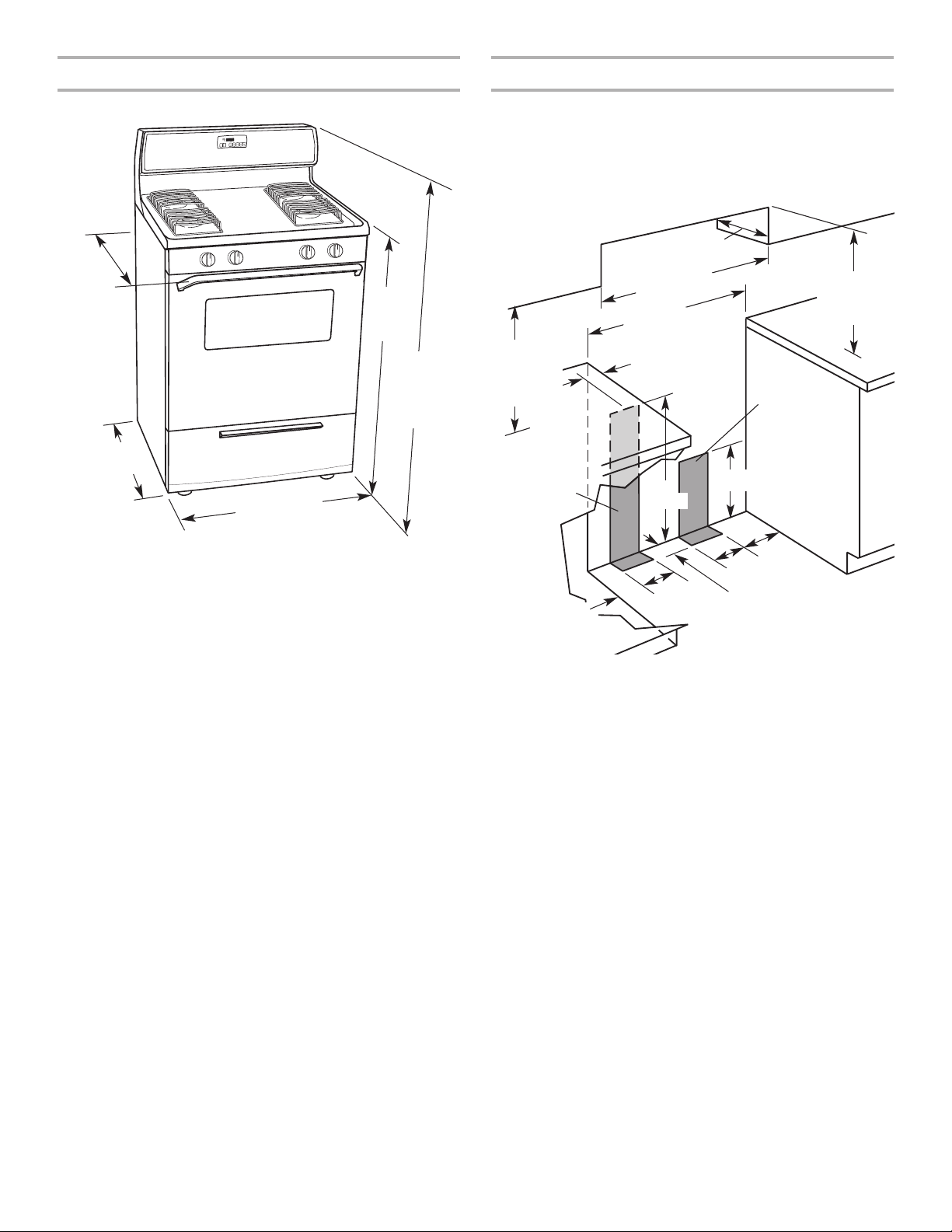
Cabinet opening dimensions shown are for 25" (64 cm)
countertop depth, 24" (61 cm) base cabinet depth and
36" (91.4 cm) countertop height.
If the cabinet depth is greater than 24" (61 cm), the oven frame
must extend beyond cabinet fronts by ¹⁄₂" (13 mm) minimum.
NOTE: 24" (61 cm) minimum when bottom of wood or metal
cabinet is protected by not less than ¹⁄₄" (0.64 cm) flame retardant
millboard covered with not less than No. 28 MSG sheet steel,
0.015" (0.4 mm) stainless steel, 0.024" (0.6 mm) aluminum or
0.020" (0.5 mm) copper.
30" (76.2 cm) minimum clearance between the top of the cooking
platform and the bottom of an unprotected wood or metal
cabinet.
If installing a range hood or microwave hood combination above
the range, follow the range hood or microwave hood combination
installation instructions for dimensional clearances above the
cooktop surface.
5
For minimum
clearance to
top of cooktop,
see NOTE.
This shaded area
recommended for
installation
of gas pipe.
This shaded area
recommended for
electrical outlet.
18" (45.7 cm)
min. clearance
upper side
cabinet to
countertop
13" (33.0 cm) max.
upper cabinet depth
30-1/8" (76.5 cm)
opening width
30" (76.2 cm) min.
cabinet opening width
8"
(20.3 cm)
2"
(5.1 cm)
3"
(7.6 cm)
5"
(12.7 cm)
5"
(12.7 cm)
10" (25.4 cm)
2" (5.1 cm) min.
countertop space to
side wall or other
combustible material
Product Dimensions
29-7/8" width
29-7/8" (75.9 cm)
width
46-1/4"
(117.5 cm)
overall height
for tall
backguard
models
24-1/4"
(61.6 cm)
36"
(91.4 cm)
cooktop
height
26-3/4"
(67.9 cm)
depth with
handle
24"
(61.0 cm)
Page 6
Gas Supply Requirements
Observe all governing codes and ordinances.
IMPORTANT: This installation must conform with all local codes
and ordinances. In the absence of local codes, installation must
conform with American National Standard, National Fuel Gas
Code ANSI Z223.1 - latest edition.
Type of Gas
Natural Gas:
This range is design-certified by the CSA International for use
with natural gas or, after proper conversion, for use with LP gas.
■ This range is factory set for use with natural gas. See “Gas
Conversions” section. The model/serial rating plate located on
the frame behind the broiler door has information on the types
of gas that can be used. If the types of gas listed do not
include the type of gas available, check with the local gas
supplier.
LP Gas conversion:
Conversion must be done by a qualified service technician.
No attempt shall be made to convert the appliance from the gas
specified on the model/serial rating plate for use with a different
gas without consulting the serving gas supplier. See “Gas
Conversions” section.
Gas Supply Line
■ Provide a gas supply line of ³⁄₄" rigid pipe to the range
location. A smaller size pipe on longer runs may result in
insufficient gas supply. Pipe joint compounds that resist the
action of LP gas must be used. Do not use TEFLON
®†
tape.
With LP gas, piping or tubing size can be ¹⁄₂" minimum.
Usually, LP gas suppliers determine the size and materials
used in the system.
Electrical Requirements
IMPORTANT: The range must be electrically grounded in
accordance with local codes and ordinances, or in the absence
of local codes, with the National Electrical Code, ANSI/NFPA 70,
latest edition.
If codes permit and a separate ground wire is used, it is
recommended that a qualified electrical installer determine that
the ground path is adequate.
A copy of the above code standards can be obtained from:
National Fire Protection Association
One Batterymarch Park, Quincy, MA 02269
CSA International
8501 East Pleasant Valley Road
Cleveland, Ohio 44131-5575
■ A 120-volt, 60-Hz, AC-only, 15-amp, fused electrical circuit
is required. A time-delay fuse or circuit breaker is also
recommended. It is recommended that a separate circuit
serving only this range be provided.
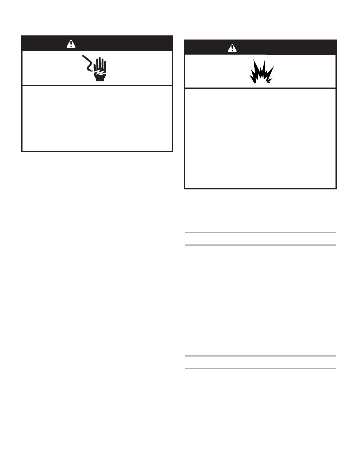
■ This range is equipped with a power supply cord having a 3
prong ground plug. To minimize possible shock hazard, the
cord must be plugged into a mating 3 prong, grounded outlet.
■ Electronic ignition systems operate within wide voltage limits,
but proper grounding and polarity are necessary. Check that
the outlet provides 120-volt power and is correctly grounded.
This range is equipped with an electronic ignition system that
will not operate if plugged into an outlet that is not properly
polarized.
■ The wiring diagram is located on the back of the range.
NOTE: The metal chassis of the range must be grounded in order
for the control panel to work. If the metal chassis of the range is
not grounded, no keypads will operate. Check with a qualified
electrician if you are in doubt as to whether the metal chassis of
the range is grounded.
6
WARNING
Electrical Shock Hazard
Plug into a grounded 3 prong outlet.
Do not remove ground prong.
Do not use an adapter.
Do not use an extension cord.
Failure to follow these instructions can result in death,
fire, or electrical shock.
WARNING
Explosion Hazard
Use a new CSA International approved gas supply line.
Install a shut-off valve.
Securely tighten all gas connections.
If connected to LP, have a qualified person make sure
gas pressure does not exceed 14" (36 cm) water
column.
Examples of a qualified person include:
licensed heating personnel,
authorized gas company personnel, and
authorized service personnel.
Failure to do so can result in death, explosion, or fire.
Page 7
7
†®TEFLON is a registered trademark of E.I. Du Pont De Nemours and Company.
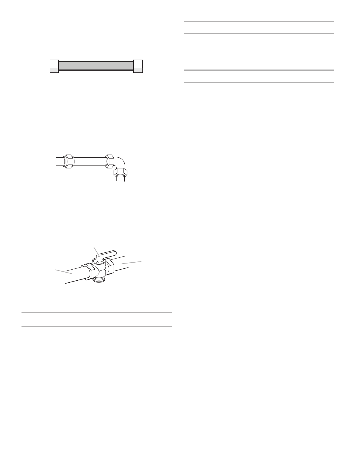
Flexible metal appliance connector:
■ If local codes permit, a new CSA design-certified, 4-5 ft
(122-152.4 cm) long, ¹⁄₂" (1.3 cm) or ³⁄₄" (1.9 cm) I.D., flexible
metal appliance connector may be used for connecting range
to the gas supply line.
■ A ¹⁄₂" (1.3 cm) male pipe thread is needed for connection to
the female pipe threads of the inlet to the appliance gas
pressure regulator.
■ Do not kink or damage the flexible metal tubing when moving
the range.
Rigid pipe connection:
The rigid pipe connection requires a combination of pipe fittings
to obtain an in-line connection to the range. The rigid pipe must
be level with the range connection. All strains must be removed
from the supply and fuel lines so range will be level and in line.
■ Must include a shutoff valve:
The supply line must be equipped with a manual shutoff
valve. This valve should be located in the same room but
external to the range. It should be in a location that allows
ease of opening and closing. Do not block access to shutoff
valve. The valve is for turning on or shutting off gas to the
range.
Gas Pressure Regulator
The gas pressure regulator supplied with this range must be
used. The inlet pressure to the regulator should be as follows for
proper operation:
Natural Gas:
Minimum pressure: 5" WCP
Maximum pressure: 14" WCP
LP Gas:
Minimum pressure: 11" WCP
Maximum pressure: 14" WCP
Contact local gas supplier if you are not sure about the inlet
pressure.
Burner Input Requirements
Input ratings shown on the model/serial rating plate are for
elevations up to 2,000 ft (609.6 m).
For elevations above 2,000 ft (609.6 m), ratings are reduced at a
rate of 4% for each 1,000 ft (304.8 m) above sea level.
Gas Supply Pressure Testing
Line pressure testing above ¹⁄₂ psi gauge (14" WCP)
The range and its individual manual shutoff valve must be
disconnected from the gas supply piping system during any
pressure testing of that system at test pressures greater than
¹⁄₂ psi (3.5 kPa).
Line pressure testing at ¹⁄₂ psi gauge (14" WCP) or lower
The range must be isolated from the gas supply piping system by
closing its individual manual shutoff valve during any pressure
testing of that system at test pressures equal to or less than
¹⁄₂ psi (3.5 kPa).
B
C
A. Shutoff valve in “open” position
B. Gas supply line
C. To range
A
Page 8
8
INSTALLATION INSTRUCTIONS
Unpack Range
1. Do not use oven door handle to lift or move the range.
2. Remove shipping materials, tape and protective film from
range. Keep cardboard bottom under range. Remove oven
racks and parts package from inside oven.
3. Take 4 cardboard corners from the carton. Stack one
cardboard corner on top of another. Repeat with the other 2
corners. Place them lengthwise on the floor behind the range
to support the range when it is laid on its back. Using 2 or
more people, firmly grasp the range and gently lay it on its
back on the cardboard corners.
4. Pull cardboard bottom firmly to remove.
5. Use an adjustable wrench to loosen the leveling legs. Adjust
the leveling legs to the correct height. Leveling legs can be
loosened to add up to a maximum of 1" (2.5 cm). A maximum
of 3/16" (5 mm) is needed to engage the anti-tip bracket.
NOTE: If height adjustment is made when range is standing, tilt
the range back to adjust the front legs, then tilt forward to adjust
the rear legs.
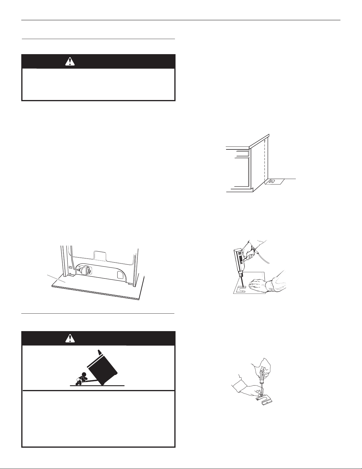
6. Place cardboard or hardboard in front of range. Using 2 or more
people, stand range back up onto cardboard or hardboard.
A
A. Cardboard shipping base
Install Anti-Tip Bracket
Contact a qualified floor covering installer for the best procedure
for drilling mounting holes through your type floor covering.
If the cabinet opening is wider than specified in the “Location
Requirements” section, adjust the template so the range will be
centered in the cabinet opening.
5. To mount the anti-tip bracket to a wood floor, drill two 1/8"
(3.2 mm) holes at the positions marked on the bracket
template. Remove the template from the floor.
To mount the anti-tip bracket to a concrete or ceramic floor, use
a 3/16" (4.8 mm) masonry drill bit to drill 2 holes at the positions
marked on the bracket template. Remove the template from the
floor.
Before moving range, slide range onto shipping base, cardboard
or hardboard.
1. Remove template from the anti-tip bracket kit (found inside
the oven cavity).
2. Place template on the floor in the cabinet opening so that the
left edge is against the cabinet and the top edge is against
the rear wall, molding or cabinet.
3. Tape template in place.
4. If the countertop is not flush with the cabinet opening edge,
align the template with the overhang.
6. Tap plastic anchors into holes with a hammer.
7. Align the anti-tip bracket holes with the holes in the floor.
Fasten the anti-tip bracket with the screws provided.
Depending on the thickness of your flooring, longer screws may
be necessary to anchor the bracket to the subfloor. Longer
screws are available from your local hardware store.
WARNING
Excessive Weight Hazard
Use two or more people to move and install range.
Failure to do so can result in back or other injury.
WARNING
Tip Over Hazard
A child or adult can tip the range and be killed.
Connect anti-tip bracket to rear range foot.
Reconnect the anti-tip bracket, if the range is moved.
Failure to follow these instructions can result in death
or serious burns to children and adults.
Page 9
9
Verify Anti-Tip Bracket Location
1. Make sure the anti-tip bracket is installed:
■ Look for the anti-tip bracket securely attached to the floor.
■ Slide the range back so the rear range foot is under the anti-tip
bracket.
2. If installing the range in a mobile home, you must secure the
range to the floor. Any method of securing the range is
adequate as long as it conforms to the standards in the
“Location Requirements” section.
3. Continue installing your range using the following installation
instructions.
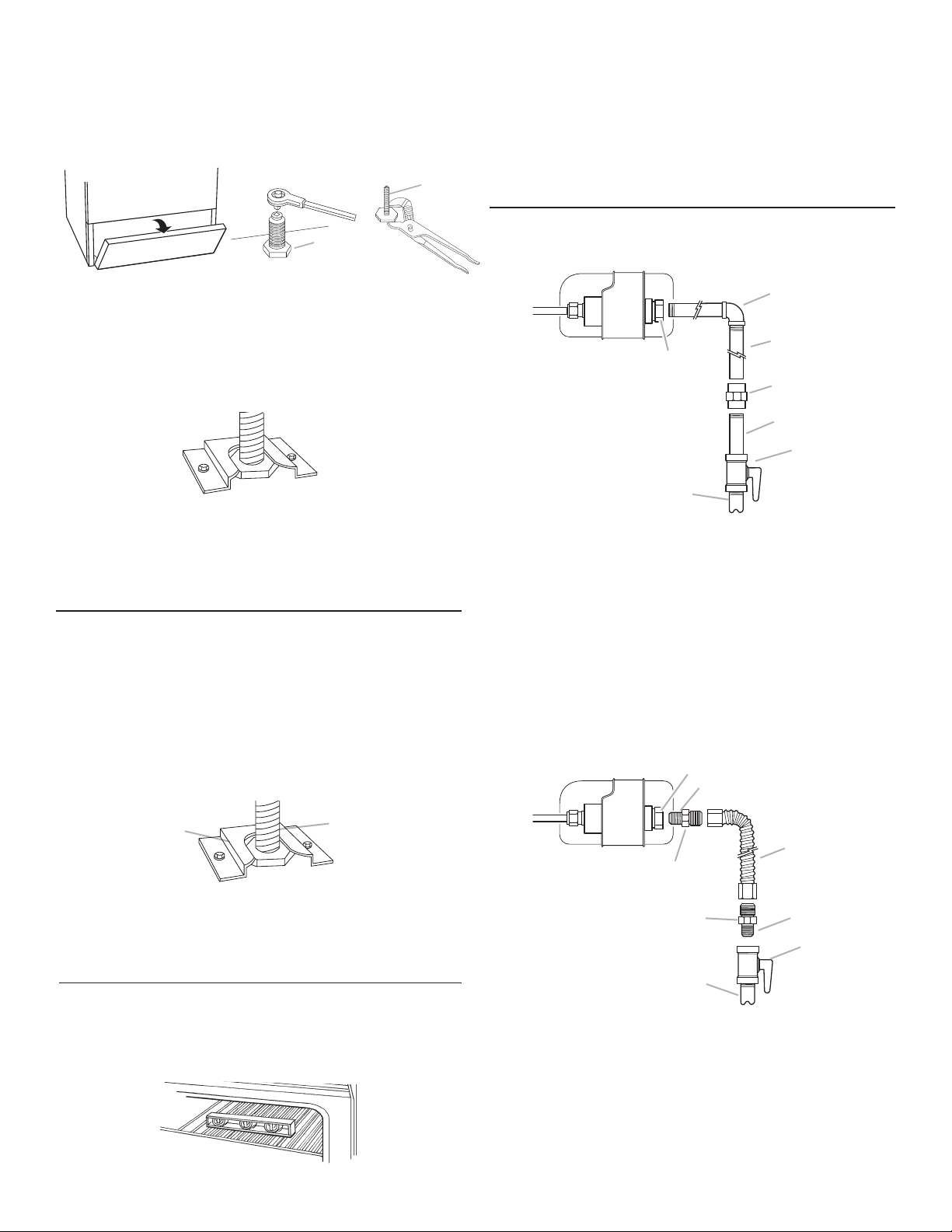
Level Range
1. Place rack in oven.
2. Place level on rack and check levelness of range, first side to
side; then front to back.
Make Gas Connection
Ty pical rigid pipe connection
Ty pical flexible connection
1. Apply pipe joint compound made for use with LP gas to all
pipe thread connections.
2. Using a pipe wrench to tighten, connect the gas supply to the
range.
3. Use a combination wrench to attach the flexible connector to
the adapters. Check that connector is not kinked.
C
E
G
H
A
D
F
B
A. Pressure regulator
connection fitting
B. Use pipe joint compound
C. Adapter
D. Flexible connector
E. Adapter
F. Use pipe joint compound
G. Manual shutoff valve
H. ¹⁄₂" to ³⁄₄" gas pipe
G
E
F
C
D
A
A. Pressure regulator
connection fitting
B. 90˚ elbow
C. Black iron pipe
D. Union
E. Nipple
F. Manual shutoff valve
G. ¹⁄₂" to ³⁄₄" gas pipe
B
8. Move the range close to the opening. Remove the shipping
base, cardboard or hardboard from under the range.
9. Open the broiler door. Use a 3/8" drive ratchet to lower the
rear leveling legs one-half turn. Use flip-joint pliers to lower
the front leveling legs one-half turn.
10. Adjust the leveling
legs to the correct
height. Leveling legs can be loosened to add up to a
maximum of 1" (2.5 cm). A minimum of 3/16" (5 mm) is
needed to engage the anti-tip bracket.
11. Move the range into final position making sure the rear
leveling leg slides into the anti-tip bracket.
12. If installing the range in a mobile home, you must secure the
range to the floor. Any method of securing the range is
adequate as long as it conforms to the standards in the
“Location Requirements” section.
13. Continue installing your range using the following installation
instructions.
A
B
A. Rear leveling leg
B. Front leveling leg
3. If range is not level, pull range forward until rear leveling leg is
removed from the anti-tip bracket. Use ³⁄₈" drive ratchet and
slip-joint pliers to adjust leveling legs up or down until range is
level.
4. Push range back into position.
5. Check that rear leveling leg is engaged in anti-tip bracket.
NOTE: Range must be level for satisfactory baking performance.
A
B
A. Anti-tip bracket
B. Range foot
Page 10
10
Check Operation
Electronic Ignition System
Cooktop and oven burners use electronic ignitors in place of
standing pilots. When a cooktop control knob is turned to the
“LITE” position, the system creates a spark to light the burner.
This sparking continues until the control knob is turned to the
desired setting.
When the oven control is turned to the desired setting, a hot
surface ignitor heats to a bright orange and ignites the gas. No
sparking occurs. The glow bar remains on while the burner
operates.
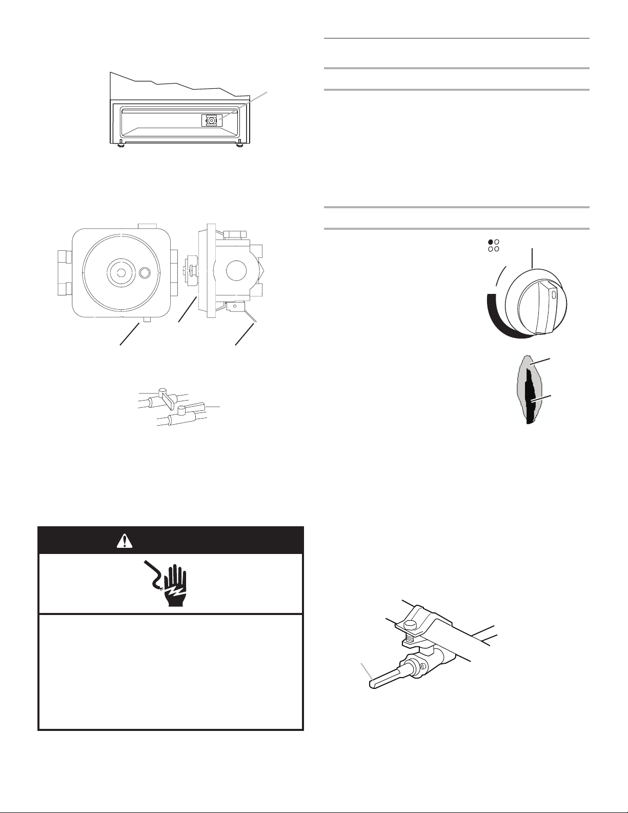
Check Operation of Cooktop Burners
1. If control panel and knobs were
removed earlier, reinstall knobs.
2. Push in and turn each surface
unit control knob to “LITE”
position. The flame should light
within 4 seconds.
3. Turn control knob to “HI”
position after burner lights.
4. Check each cooktop burner for
proper flame. The small inner
cone should have a very distinct blue
flame ¹⁄₄" (6.4 mm) to ¹⁄₂" (13 mm) long.
The outer cone is not as distinct as the
inner cone.
5. Turn the control knob quickly to the “LO”
position after the burner lights. If the
flame goes out, turn the control knob to the “OFF” position.
6. Check each cooktop burner for proper low flame. The low
flame should be a minimum, steady blue flame. The flame size
should be ¹⁄₄" to ³⁄₈" (6.4 mm to 9.5 mm) high.
If the low flame needs adjusting:
1. Turn control knob to the “LO” setting and remove control
knob.
2. Insert a small flat-blade screwdriver into the valve stem. Turn
the valve adjusting screw to obtain the smallest flame that will
not go out when the control of a cold burner is quickly turned
from “HI” to “LO”. Turn right to decrease flame height. Turn
left to increase flame height. Repeat for other cooktop burners
as needed.
3. Replace control knob.
Complete Connection
1. Locate gas pressure regulator in the broiler.
IMPORTANT: Do not remove the gas pressure regulator.
2. Check that the gas pressure regulator shutoff valve is in the
“ON” position.
3. Open the manual shutoff valve in the gas supply line. The
valve is “open” when the handle is parallel to the gas pipe.
4. Test all connections by brushing on an approved noncorrosive
leak-detection solution. Bubbles will show a leak. Correct any
leak found.
5. Close the broiler door.
6. Place burners, burner caps and grates on the cooktop.
7. Plug into a grounded 3-prong outlet.
outer
cone
inner
cone
A. Valve stem
A
A
Shutoff valve
“ON” Position
Front
Front ViewFront View
Side View
Gas Pressure Regulator
A. Gas pressu re r egu lator
A
B
A. Closed valve
B. Open valve
WARNING
LITE
HI
OFF
LO
MED
Electrical Shock Hazard
Plug into a grounded 3 prong outlet.
Do not remove ground prong.
Do not use an adapter.
Do not use an extension cord.
Failure to follow these instructions can result in death,
fire, or electrical shock.
Page 11
11
6. When the flame has been properly adjusted, turn the oven off,
wait for the burner to cool down.
7. Tighten the shutter screw.
8. Reinstall flame spreader and oven tray. Reinstall the oven
racks and close oven door.
9. Close the broiler door.
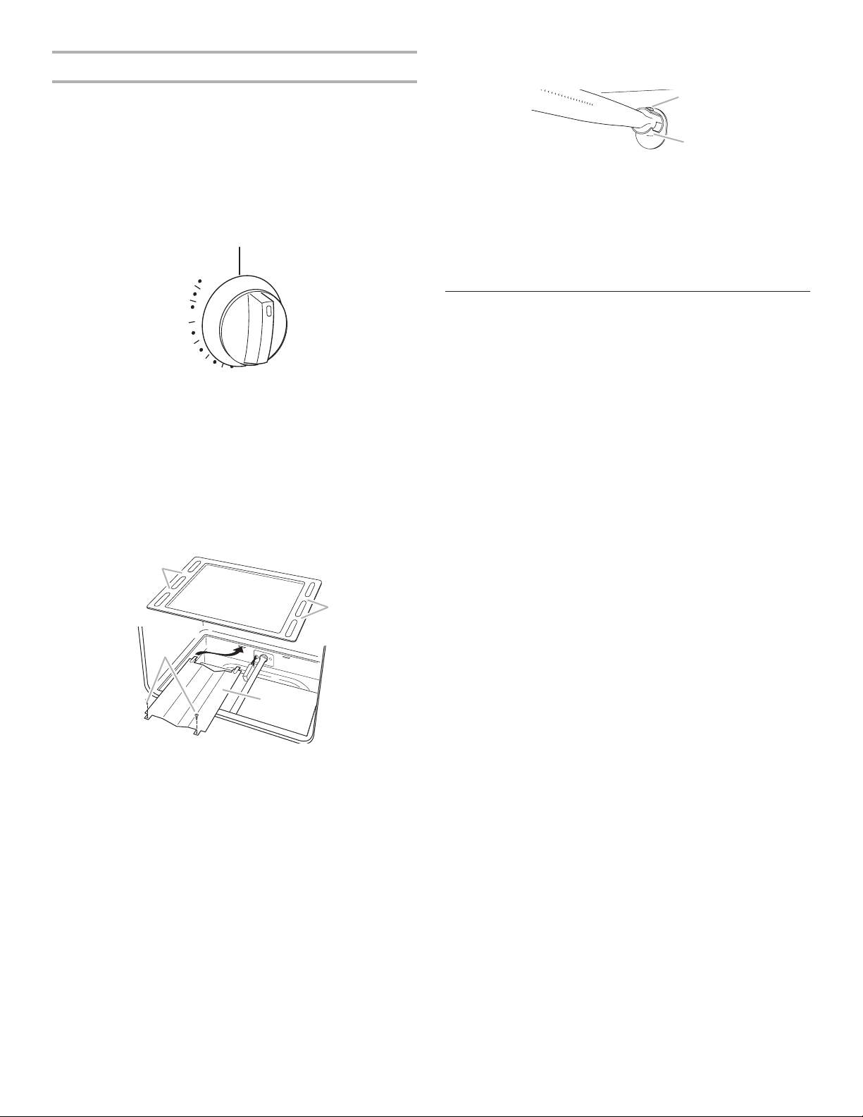
Check Operation of Oven/Broil Burner
1. Open broiler door.
2. Push in and turn the oven control knob to “350˚F.” The oven
pilot should now be larger with the flame burning against a
small metal bulb. The oven burner should light in 20–40
seconds; this delay is normal. The oven valve requires a
certain time before it will open and allow gas to flow.
To avoid damaging the hot surface ignitor, do not insert any
object into the openings of the protective shield that
surrounds the ignitor or clean that area.
3. Check the oven burner for proper flame. The flame should be
¹⁄₂" (13 mm) long, with inner cone of bluish-green, and outer
mantle of dark blue, and should be clean and soft in
character. No yellow tips (not enough air), blowing or lifting
(too much air) of flame should occur.
If the flame needs adjusting:
1. Turn the oven off. Wait for the oven burner to cool down.
2. Open oven door and remove oven racks, oven tray, flame
spreader and set aside.
3. Locate the air shutter near the rear wall of oven and loosen
the shutter screw.
4. Adjust the air shutter.
5. Turn the oven back on and check for proper flame. If the
flame is still not properly adjusted, turn the oven off, wait for
the oven burner to cool down and repeat step 4 until flame is
properly adjusted.
B
C
A
A. Oven tray (lift up at area shown to remove)
B. Screws
C. Flame spreader
A
A. Shutter screw
B. Air shutter
B
A
Complete Installation
1. Check to be sure all parts are now installed. If there is an
extra part, go back through the steps to see which step was
skipped.
2. Check to be sure you have all of your tools.
3. Dispose of/recycle all packaging materials.
4. Check to be sure the range is level. See “Level Range.”
5. Use a mild solution of liquid household cleaner and warm
water to remove waxy residue caused by protective shipping
material. Dry thoroughly with a soft cloth.
6. For range use and cleaning, read the range Use and Care
Guide.
7. Turn on surface burners and oven.
If range does not operate, check the following:
■ Household fuse is intact and tight; or circuit breaker has not
tripped.
■ Range is plugged in to a grounded 3 prong outlet.
■ Electrical supply is connected.
■ See “Troubleshooting” in your Use and Care Guide.
■ When the range has been on for 5 minutes, feel for heat. If
you do not feel heat, turn the range off and check to see that
the gas supply line shutoff valve is open.
■ If the gas supply line shutoff valve is closed, open it, then
repeat the 5-minute test as outlined above.
■ If the gas supply line shutoff valve is open, contact a
qualified technician.
OFF
140
170
200
250
300
OVEN
350
TEMP
400
BROIL
350
450
Page 12
12
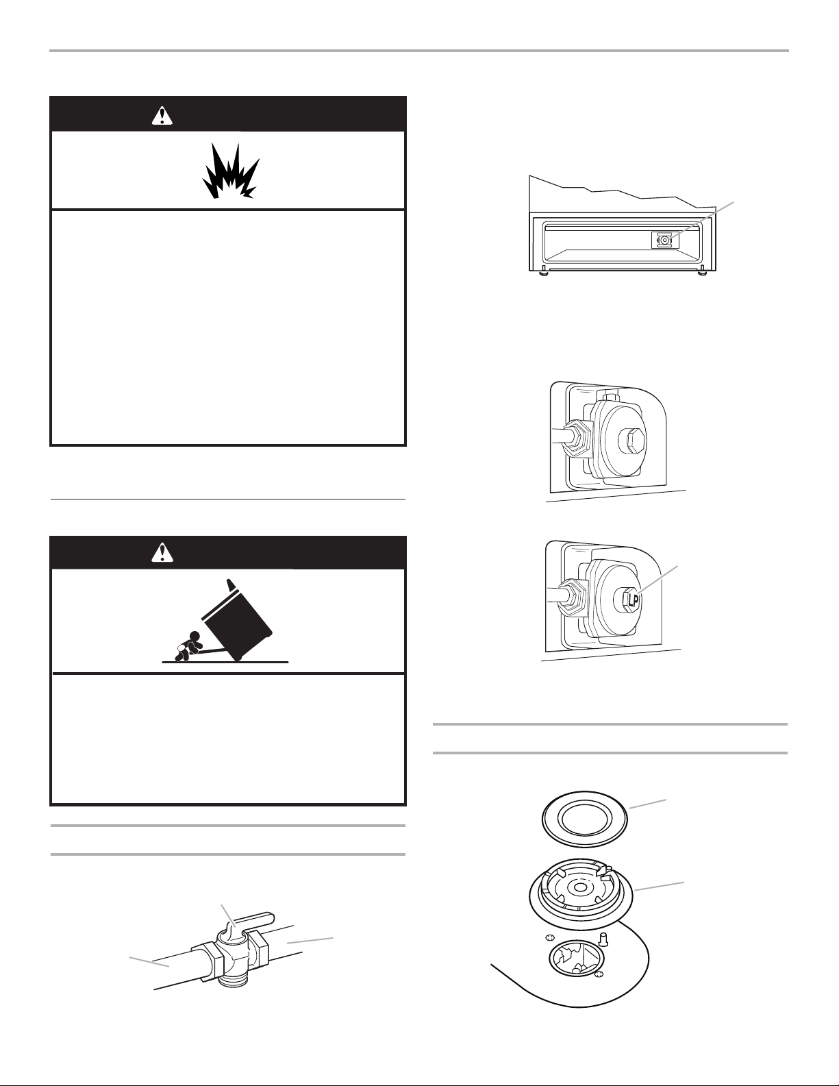
2. Unplug or disconnect power.
3. Open broiler door and remove broiler pan. The gas pressure
regulator is located in the back right hand corner of the broiler
compartment.
IMPORTANT: Do not remove the gas pressure regulator.
NOTE: Do not remove the spring beneath the cap.
4. Remove the cap from the gas pressure regulator using a flatblade screwdriver.
5. Turn the cap over so that LP is visible.
6. Reinstall the cap.
To Convert Surface Burners
1. Remove burner grate, burner caps, and burners.
A
A. Burner cap
B. Burner
B
A
A. Cap
GAS CONVERSIONS
LP Gas Conversion
To Convert Gas Pressure Regulator
1. Ensure that the manual shutoff valve is in the closed position.
NOTE: Gas conversions (from natural gas to LP gas or from LP
gas to natural gas) must be done by a qualified person.
B
C
A. Shutoff valve in “open” position
B. Gas supply line
C. To range
A. Gas pressu re r egu lator
A
WARNING
Explosion Hazard
Use a new CSA International approved gas supply line.
Install a shut-off valve.
Securely tighten all gas connections.
If connected to LP, have a qualified person make sure
gas pressure does not exceed 14" (36 cm) water
column.
Examples of a qualified person include:
licensed heating personnel,
authorized gas company personnel, and
authorized service personnel.
Failure to do so can result in death, explosion, or fire.
WARNING
Tip Over Hazard
A child or adult can tip the range and be killed.
Connect anti-tip bracket to rear range foot.
Reconnect the anti-tip bracket, if the range is moved.
Failure to follow these instructions can result in death
or serious burns to children and adults.
A
A. Shutoff valve in “open” position
Page 13
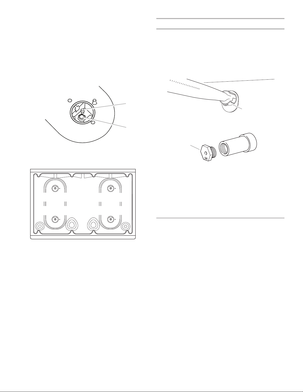
2. Locate LP gas orifice spuds for top burners in the bag
containing literature included with the range. Three LP gas
spuds are stamped “88” and one “96.”
3. Remove natural gas orifice spuds using a 7mm combination
wrench.
4. Install LP gas orifice spuds.
NOTE: Depending on model, the range cooktop may be
equipped with 4 standard burners or 3 standard burners and
1 power burner. Spud size/location remain the same.
5. Place the natural gas orifice spuds in the parts bag for future
use and keep with bag containing literature.
6. Reinstall burners, burner caps and burner grates.
To Convert Oven Burner
1. Open oven door and remove oven racks, oven tray, flame
spreader and set aside.
2. Lift oven burner. The orifice spud is behind the oven burner air
shutter.
3. Locate LP gas orifice spud stamped “56” in literature package
supplied with range.
4. Use a ³⁄₈" combination wrench and remove the natural gas
orifice spud.
5. Install the number “56” LP gas spud.
IMPORTANT: Do not over tighten.
6. Place natural gas oven burner spud in plastic parts bag along
with natural gas cooktop burner spuds for future use and
keep with bag containing literature.
7. Reinstall oven burner.
8. Reinstall oven racks, oven tray and flame spreader.
Complete Conversion
1. Refer to the “Make Gas Connection” section for properly
connecting the range to the gas supply.
2. Turn the manual shutoff valve in the gas supply line on.
3. Refer to the “Check Operation” section for proper burner
ignition, operation, and burner flame adjustments.
IMPORTANT: You may have to adjust the “LO” setting for
each cooktop burner.
Checking for proper cooktop and oven burner flames is very
important. The small inner cone should have a very distinct
blue flame ¹⁄₄" to ¹⁄₂" (6.4 mm to 13 mm) long. The outer cone
is not as distinct as the inner cone. LP gas flames have a
slightly yellow tip.
4. Close the broiler door and turn the knob to “OFF”.
5. Refer to the “Complete Installation” section to complete this
procedure.
13
A
A. Spud
B. Holder
B
A
A. LP oven orifice spud stamped with “56”
A
A. Air shutter
Std burner 88
Std burner 88
Std burner 88
Power burner 96
Page 14
14
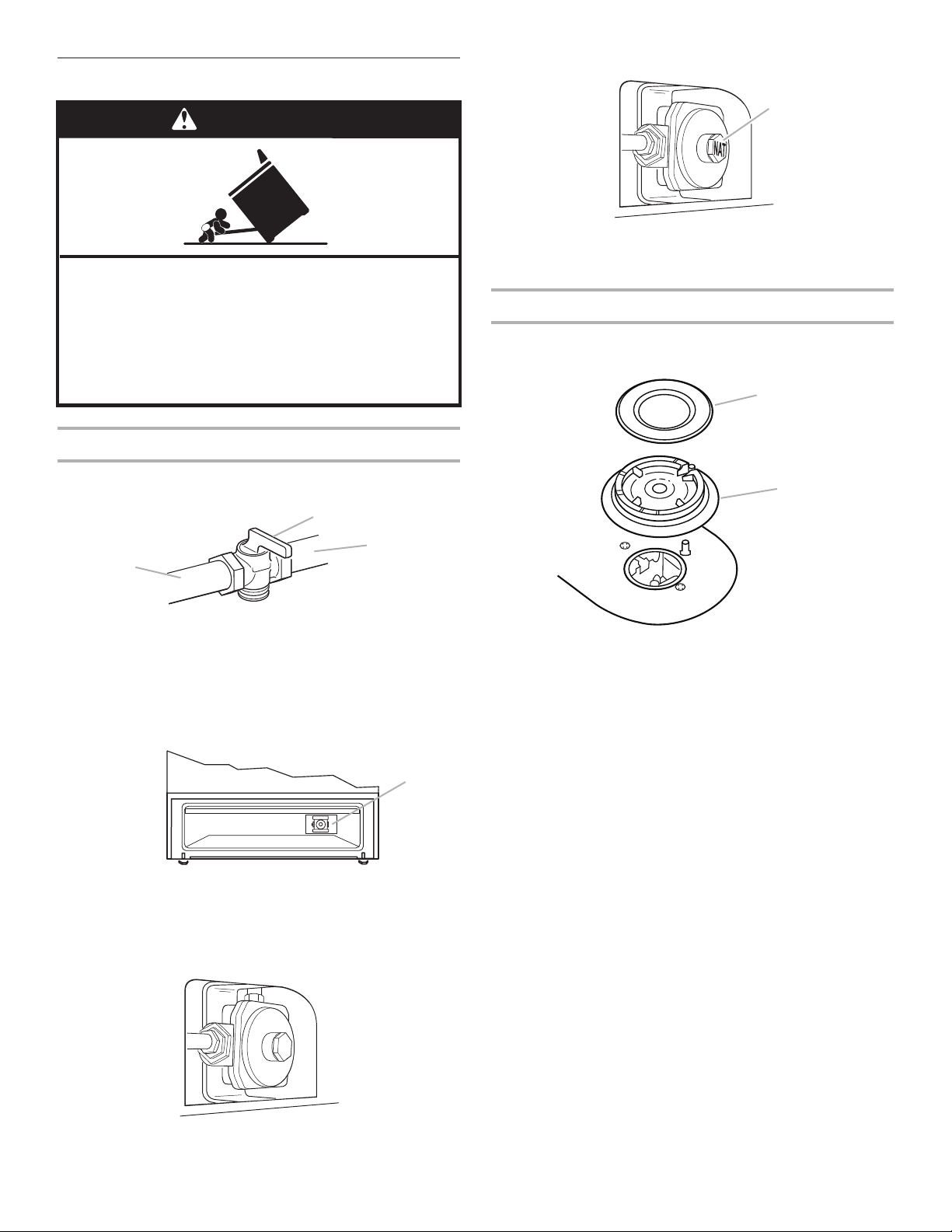
5. Turn the cap over so that N or NAT is visible.
6. Reinstall the cap.
To Convert Surface Burners
1. Remove burner grates, burner caps, and burners.
2. Locate the natural gas orifice spuds for the top burners in the
bag containing literature included with the range. Three
natural gas spuds are stamped “149” and one “165.”
3. Remove the LP gas orifice spuds using a 7mm combination
wrench.
Natural Gas Conversion
To Convert Gas Pressure Regulator
1. Ensure that the manual shutoff valve is in the closed position.
2. Unplug or disconnect power.
3. Open broiler door and remove broiler pan. The gas pressure
regulator is located in the back right hand corner of the broiler
compartment.
IMPORTANT: Do not remove the gas pressure regulator.
NOTE: Do not remove the spring beneath the cap.
4. Remove the cap from the gas pressure regulator using a flatblade screwdriver.
A
A. Cap
A
A. Burner cap
B. Burner
B
B
C
A. Shutoff valve in “open” position
B. Gas supply line
C. To range
A. Gas pressu re r egu lator
A
WARNING
Tip Over Hazard
A child or adult can tip the range and be killed.
Connect anti-tip bracket to rear range foot.
Reconnect the anti-tip bracket, if the range is moved.
Failure to follow these instructions can result in death
or serious burns to children and adults.
A
Page 15
15
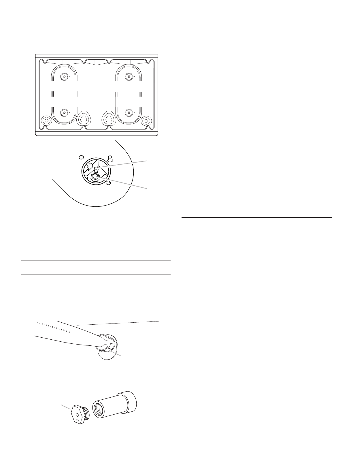
4. Install natural gas orifice spuds.
NOTE: Depending on model, the range cooktop may be
equipped with 4 standard burners or 3 standard burners and
1 power burner. Spud size/location remain the same.
5. Place LP gas orifice spuds in the plastic parts bag for future
use and keep with the bag containing literature.
6. Reinstall burners, burner caps and burner grates.
To Convert Oven Burner
1. Open oven door and remove oven racks, oven tray, flame
spreader and set aside.
2. Lift oven burner. The orifice spud is behind the oven burner air
shutter.
3. Locate natural gas orifice spud stamped “47” in literature
package supplied with range.
4. Use a ³⁄₈" combination wrench and remove the LP gas orifice
spud.
A
A. Spud
B. Holder
B
5. Install the number “47” natural gas spud.
IMPORTANT: Do not over tighten.
6. Place LP gas oven burner spud in plastic parts bag along
with LP gas cooktop burner spuds for future use and keep
with bag containing literature.
7. Reinstall oven burner.
8. Reinstall oven racks, oven tray and flame spreader.
Complete Conversion
1. Refer to the “Make Gas Connection” section for properly
connecting the range to the gas supply.
2. Turn the manual shutoff valve in the gas supply line on.
3. Refer to the “Check Operation” section for proper burner
ignition, operation, and burner flame adjustments.
IMPORTANT: You may have to adjust the “LO” setting for
each cooktop burner.
Checking for proper cooktop and oven burner flames is very
important. The small inner cone should have a very distinct
blue flame ¹⁄₄" to ¹⁄₂" (6.4 mm to 13 mm long). The outer cone
is not as distinct as the inner cone. Natural gas flames do not
have yellow tips.
4. Close the broiler door and press the “OFF” pad.
5. Refer to the “Complete Installation” section to complete this
procedure.
Std burner 149
Std burner 149
Std burner 149
Power burner 165
A
A. Natural gas oven orifice spud stamped with “47”
A
A. Air shutter
Page 16

W10032070
©2006 Whirlpool Corporation
All rights reserved.
Printed in Mexico
07/2006
 Loading...