How it Works
Log In / Sign Up
Buy Points
How it Works
FAQ
Contact Us
Questions and Suggestions
Users
Whirlpool
Loading...
T
TGP325
TGP325E
TGP325MQ0
TGR51
TGR51W0
TGR51WO
TGR51WOW
TGR61W2B
TGR88W2B
TGS325E
TGS325E W
2
TGS325G
2
TGS325KQ2
TGS325MQ3
TGV 3400 IN
5
TGV 3402
2
TGV 3402-1 IN
7
TGV 3402 IN
3
TGV 3402 SW
3
TGV 3402 WS
3
TGV 3404-1 SW
3
TGV 3404-2 SW
3
TGV 3404 SW
3
TGV 3405
TGV 3405-1 SW
6
TGV 3405 SW
7
TGV 3410-1 SW
5
TGV 3410-2 SW
5
TGV 3410-2 WS
5
TGV 3410-3 SW
5
TGV 3410 SW
3
TGV 3411
TGV 3411-1 SW
6
TGV 3411 SW
6
TGV 3412-1 SW
2
TGV 3412 SW
2
TGV 3413-1 SW
3
TGV 3413-1 WS
3
TGV 3413 SW
3
TGV 3413 WS
3
TGV 3420-1 SW
2
TGV 3520-1 SW
5
TGV 3520-2 SW
3
TGV 3520/3 SW
3
TGV 3520 SW
5
TGV 3520 SW-3
2
TGV 3570 IN
4
TGV 5460 SW
3
TGV 5461
3
TGV 5461 SW
5
TGV 5470/SW
9
TGV 5471
2
TGV 5471 SW
6
TGV 5590 SW
2
TGV 5591
2
TGV 5591 SW
6
TGV 6160/IN
3
TGV 6730 IN
5
TGV 6731/IN
5
TGV 7400
TGV 7400 SW
5
TGV 7400 TI
7
TGV 7401
TGV 7401 TI
8
TGW 3563 IN
6
TGW 3571 IN
7
TGW 3573 IN
4
TGW 5360
TGW 5360 IN
3
TGW 5460 IN
2
TGW 5465 IN
2
TGW 5465/IN/01
3
TGW 5465 IXL
4
TGW 5465/PT
2
TGW 5466
2
TGW 5466 IN
2
TGW 5466/IN/01
3
TGW 5466 IXL
4
TGW 5475 IN
2
TGW 5475/IN/01
4
TGW 5475/PT
4
TGW 5476/IN
3
TGW 5500 SW
8
TGW 5575
TGW 5575 IN
2
TGW 5575/IN/01
3
TGW 5575 IXL
3
TGW 5575/PT
TGW 5576
2
TGW 5576/IN
4
TGW 5576/IN/01
5
TGW 5576 IXL
6
TGW 5576/PT
2
TGW 5595
2
TGW 5595/IN
4
TGW 5595/IN/01
2
TGW 5595 IXL
2
TGW 5675/IN
4
TGW 5675 IXL
3
TGW 5675/PT
2
Loading...
Loading...
Nothing found
TGV 5470/SW
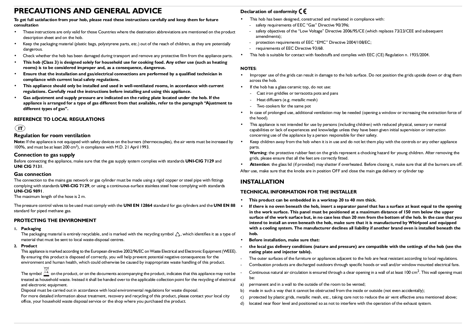
INSTRUCTION FOR USE
4 pgs
543.43 Kb
0
PROGRAM CHART
4 pgs
1.37 Mb
0
PROGRAM CHART
4 pgs
130.18 Kb
0
PROGRAM CHART [de]
4 pgs
1.41 Mb
0
PROGRAM CHART [de]
4 pgs
125.2 Kb
0
PROGRAM CHART [nl]
4 pgs
133.84 Kb
0
PROGRAM CHART [nl]
4 pgs
1.36 Mb
0
User Manual [hu]
4 pgs
1.37 Mb
0
User Manual [it]
4 pgs
507.79 Kb
0
Table of contents
Loading...
Whirlpool TGV 5470/SW INSTRUCTION FOR USE
...
Whirlpool INSTRUCTION FOR USE
Download
Specifications and Main Features
Frequently Asked Questions
User Manual
Download
Loading...
+
2
hidden pages
Unhide
You need points to download manuals.
1 point = 1 manual.
You can buy points or you can get point for every manual you upload.
Buy points
Upload your manuals