

Page 1
TGV 3412 PRODUCT DESCRIPTION SHEET
IT PT
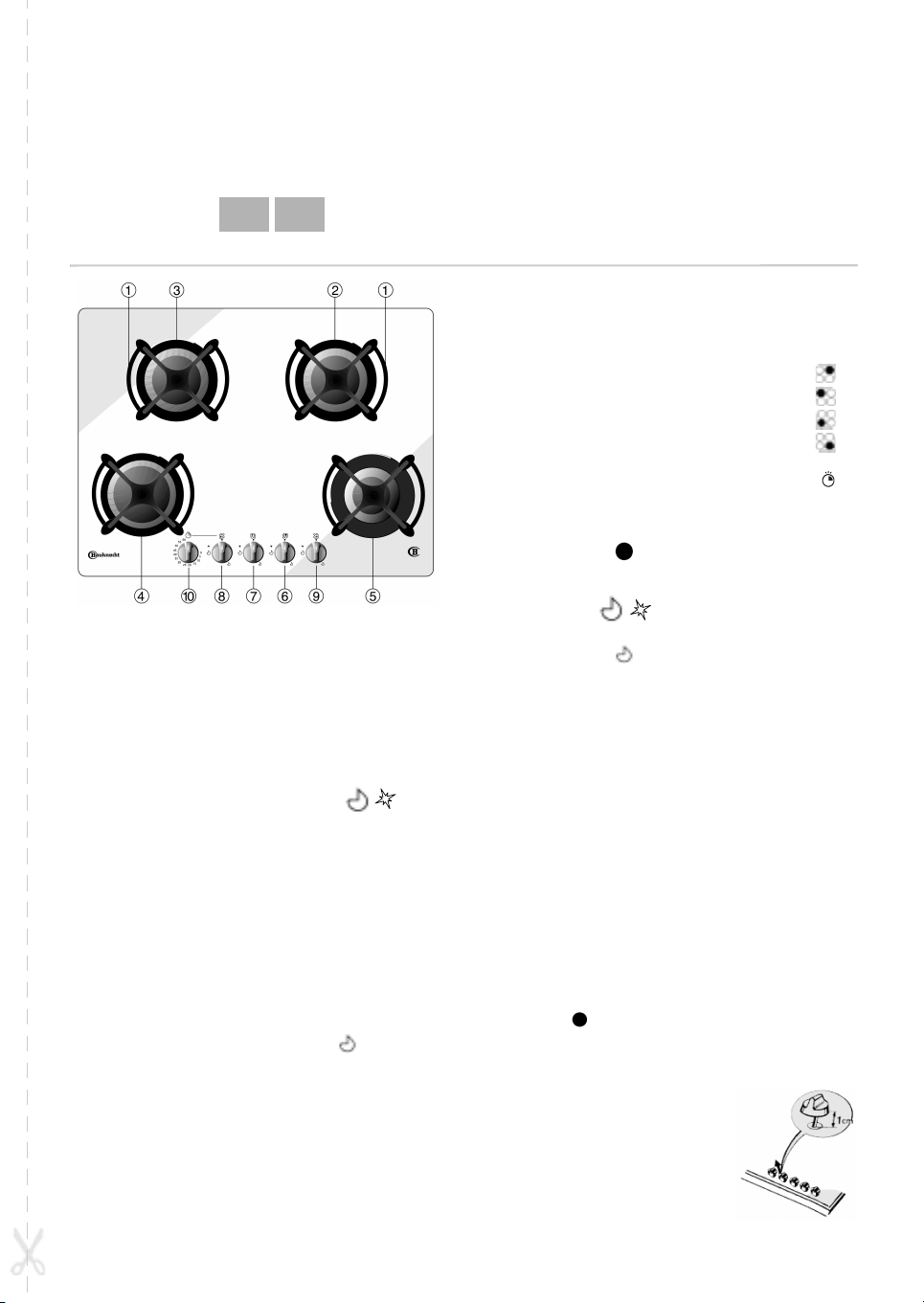
1.
Removable panstand grids
2.
Large burner
3-4.
Medium burners
5.
Small burner
6.
Large burner control knob
7.
Medium burner control knob
8.
Medium burner control knob
9.
Small burner control knob
10.
Knob for medium burner
programmer control
Symbols
Shaded circle Tap closed
Operation of burners with safety
device and electric ignition
To light one of the burners:
Press the relative knob and turn it anti-clockwise
to the large flame and star setting .
At the same time, keep the knob pressed against
the control panel until the burner ignites.
After the burner has ignited, keep the knob
pressed for about 10 seconds.
Release the knob.
If the burner does not ignite, repeat the operations
described above.
Notes:
Should particular local conditions of the delivered
gas make the ignition of the burner difficult, it is
advisable to repeat the operation with the knob
turned to the small flame setting .
The safety device of the burner shuts off the gas
supply to the burner if its flame goes out
accidentally (because of a sudden gust of wind,
an interruption in the gas delivery, the
overflowing of liquids, etc,).
Important
Improper use of the grids can result in damage to
the hob: do not position the grids upside down or
slide them across the hob.
Large flame
and star
Small flame Minimum opening or
Do not use:
cast iron griddles or terracotta pots and pans
heat diffusers such as metal mesh, or any other
types
two burners simultaneously for one receptacle
(e.g. fish kettle).
Maximum opening/delivery
and electric ignition
reduced delivery
Operation of programmer
On the medium left burner, the cooking time can be
programmed (up to 60 minutes)
Light the medium burner.
Turn the programmer knob clockwise to the
desired cooking time.
When the preset time is over, a warning bell rings,
the gas supply is shut off and the burner goes out.
Turn the burner control knob to the shaded circle
position .
Telescopic knobs
A particular mechanism makes
it possible to raise the knobs
about 1 cm, in order to clean
the surface under them.
After cleaning, put the knobs
back in their original position.
Note:
Peel the plastic film off the metal
knob insert.
5019 419 61221
Page 2
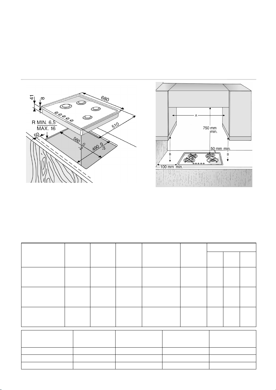
DIMENSIONS OF COOKING HOB AND WORKTOP
NOTE:
If the distance A between the wall cabinets is between 660 mm and
680 mm, the height B must be a minimum of 520 mm.
If the distance A between the wall cabinets is greater than the width
of the cooktop, the height B must be a minimum of 400 mm.
In case of installation of a hood above the cooktop, please refer to
the hood instructions for the correct distance.
INJECTORS TABLE CATEGORY II2H3+
Type of gas
used
NATURAL
GAS
(Methane) G 20
LIQUID
PETROLEUM GAS
(Cylinder) G 30
LIQUID
PETROLEUM GAS
(Cylinder) G 31
Type of gas
used
G 20 20 mbar 4 gas 7.30 695 l/h 14.6
G 25 28-30 mbar 4 gas 7.30 531 g/h 14.6
G 31 37 mbar 4 gas 7.30 521 g/h 14.6
Type of
burner
large
medium
small
large
medium
small
large
medium
small
Appliance
model
Injector
marking
129
108
78
85
65
50
85
65
50
Rated
heat
capacity
Pcs-kW
3.00
1.90
1.00
3.00
1.65
1.00
3.00
1.65
1.00
Total rated heat
capacity Pcs-kW
Rated
consumption
286 l/h
157 l/h
95 l/h
218 g/h
120 g/h
73 g/h
214 g/h
118 g/h
71 g/h
Reduced
heat
capacity
Pcs-kW
0.60
0.35
0.30
0.60
0.35
0.30
0.60
0.35
0.30
Total rated
consumption
Gas pressure
min. rat. max.
17 20 25
20 28-30 35
25 37 45
Air required for
3
burning m
/h
 Loading...