

Whirlpool SS373PEX1 User Manual
A WARNING
• ALL RANGES CAN
TiP
• INJURY TO PERSONS
COULD RESULT
• INSTALL ANTI-TIP
DEVICE PACKED
WITH RANGE
• SEE INSTALLATION
INSTRUCTIONS
Installation Instructions
IMPORTANT:
Read and save
these instructions.
Important:
Installer: Leave Installation Instructions with
the homeowner.
Homeowner: Keep Installation Instructions
for future reference.
Save Installation Instructions for local
electrical inspector's use.
Part No. 36-307563-02-0/4363123
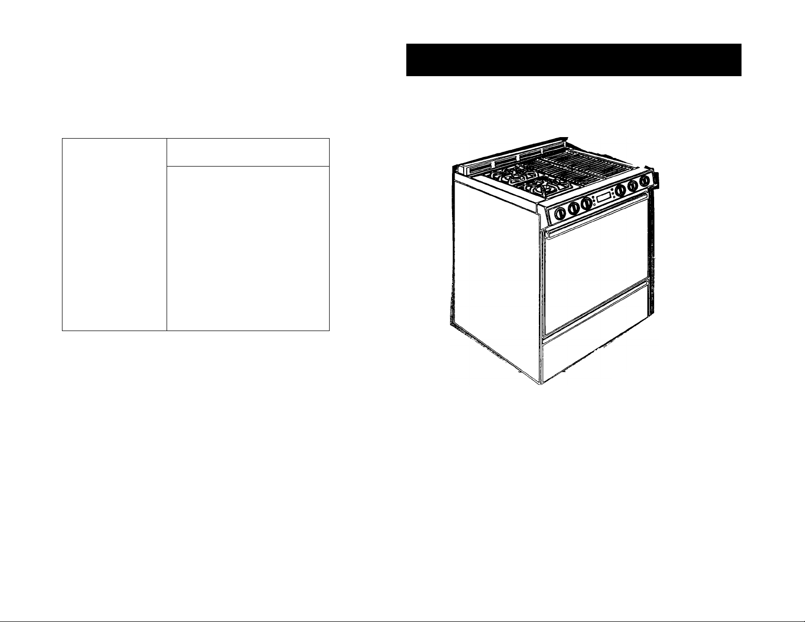
30” Gas
Downdraft
Slide-in
Range
with seif-cleaning oven
AVhirlpool
Home^^Appliances
Before yott start...
Proper installation is your responsibility.
A qualified technician should install
this range. Make sure you have
everything necessary for correct
installation. It is the responsibility of the
installer to comply with the installation
clearances specified on the
serial/rating plate. The serial/rating
plate is located on the oven frame
behind the door.
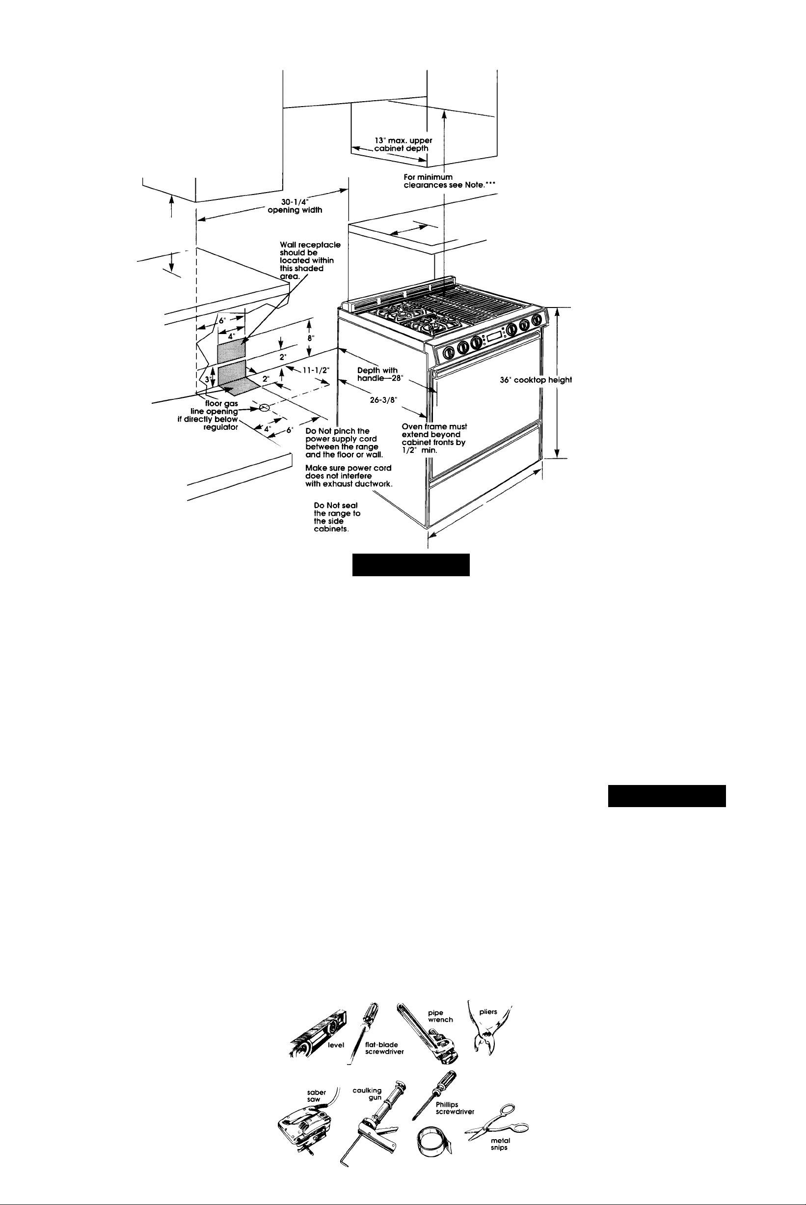
18" min
clearance
upper cabinet
to countertop
Check location where range will be
installed. The location should be
away from strong draft areas, such
as windows, doors, and strong
heating vents or fans. The range
should be located for convenient
use in the kitchen. Recessed
installations must provide complete
enclosure of the sides and rear of
range.
6" min. countertop space
from either side of range
cooktop to vertical wall or
other combustible material.
" NOTE: 30" min. when bottom of
wood or metal cabinet is
protected by not less than 1 /4"
flame retardant millboard
covered with not less than No. 28
MSG sheet steel, 0.015" stainless
steel, 0.024" aluminum or 0.020"
copper.
36” min. clearance between the
top ot the cooking platform and
the bottom of an unprotected
wood or metal cabinet.
Important:
Observe all
governing codes
and ordinances.
Gas line can be
located through the
floor or through the
wall within this
shaded area.
Grounded electrical
outlet is required. See
Electrical requirements
Proper gas supply
connection must be
available. See Gas supply
requirements.
ALL OPENINGS IN THE WALL
OR FLOOR WHERE RANGE IS
TO BE INSTALLED MUST BE
SEALED.
Gas supply line piping
MUST NOT interfere
with vent ductwork.
WARNING: If the information
in this manual is not
followed exactly, a fire or
explosion may result
causing property damage,
personal injury or death.
— Do Not store or use gasoline
or other flammabie vapors
and liquids in the vicinity of
this or any other appliance.
— WHAT TO DO IF YOU SMELL
GAS
• Do Not try to light any
appliance.
• Do Not touch any electrical
switch; Do Not use any
phone in your building.
• Immediately call your gas
supplier from a neighbor's
phone. Follow the gas
supplier's instructions.
• If you cannot reach your
gas supplier, call the fire
department.
— Installation and service must
be performed by a qualified
installer, service agency or
the gas supplier.
Copies of standards listed may be
obtained from:
* National Fire Protection Association
Batterymarch Park
Quincy, Massachusetts 02269
** American Gas Association
1515 Wilson Boulevard
Arlington, Virginia 22209
Panel A
A. WARNING
Fire Hazard
Do Not obstruct the flow of
combustion and ventilation air.
Personal Injury Hazard
Avoid installing cabinet storage
above the cooking surface. If
cabinets are already installed,
reduce the hazard of reaching over
a heated cooking surface by
installing a range hood. The range
hood should extend a minimum of 5
inches out from the bottom front of
the cabinets.
Reaching over a heated cooking
surface could result In a serious burn.
Electrical Shock Hazard
It is the customer’s responsibility:
• To contact a qualified electrical
installer.
• To assure that the electrical
installation is adequate and in
conformance with National
Electrical Code, ANSI/NFPA 70 —
latest edition*, and all local codes
and ordinances.
Failure to do so could result in fire,
electrical shock or other personal
injury.
Tools needed for
installation:
caulking gun
duct tape
metal snips
hand or electric drill
wood floors: 3/32" drill bit
concrete/ceramic lloor: 3/16” masonry drill bit
duct tape
Width —29-15/16”
Island or peninsula installations
use 24" deep, flush back base
cabinets with no rear toe space.
If rear toe space is desired, use
27" or deeper base cabinet.
Cabinet opening dimensions
that are shown must be used.
Given dimensions are
minimum clearances and
provide required 0"
clearance.
NOTE: Clearances specified are for
combustible walls and materials that
have a density of 20 or more pounds
per cubic foot. No evaluation of
clearances has been made for
installations adjacent to materials
that are less than 20 pounds per cu.
ft. or to plastic tiles and sheeting.
The anti-tip bracket MUST
be instaiied. For detaiied
instructions, see Panei D.
Gas supply
requirements
Observe all governing codes and
ordinances.
A WARNING
Fire Hazard
• Range must be connected to a
regulated gas supply. This must be
checked by a qualified technician
before installing range.
• Do Not use an open flame to test
for leaks from gas connections.
• New, A.G.A. design-certified
flexible gas line should be used
when codes permit.
Failure to follow these instructions
could result in a fire, explosion or
personal injury.
This installation must conform
with local codes and ordinances. In
the absence of local codes,
installation must conform with
American National Standard, National
Fuel Gas Code ANSI Z223.1 — latest
edition**.
В
the seriai/rating piate are for
eievations up to 2,000 feet. For
elevations above 2,000 feet, ratings
are reduced at a rate of 4% for each
1,000 feet above sea level.
Input ratings shown on
This range is equipped for use
with NATURAL gas only and is designcertified by A.G.A.
Electrical
requirements
A WARNING
Venting
requirements
Ductwork needed for left side venting
is not included.
Provide a gas supply line of
3/4" rigid pipe to the range location.
A smaller size pipe on long runs may
result in insufficient gas supply. Pipe-
joint compounds made for use with
NATURAL and L.P. gas must be used.
■ If local codes permit, A.G.A.
design-certified flexible metal tubing is
recommended for connecting this
range to the gas supply line. Do Not
kink or damage the flexible tubing
when moving the range. A 1/2" male
pipe thread is needed for connection
to pressure regulator female pipe
threads.
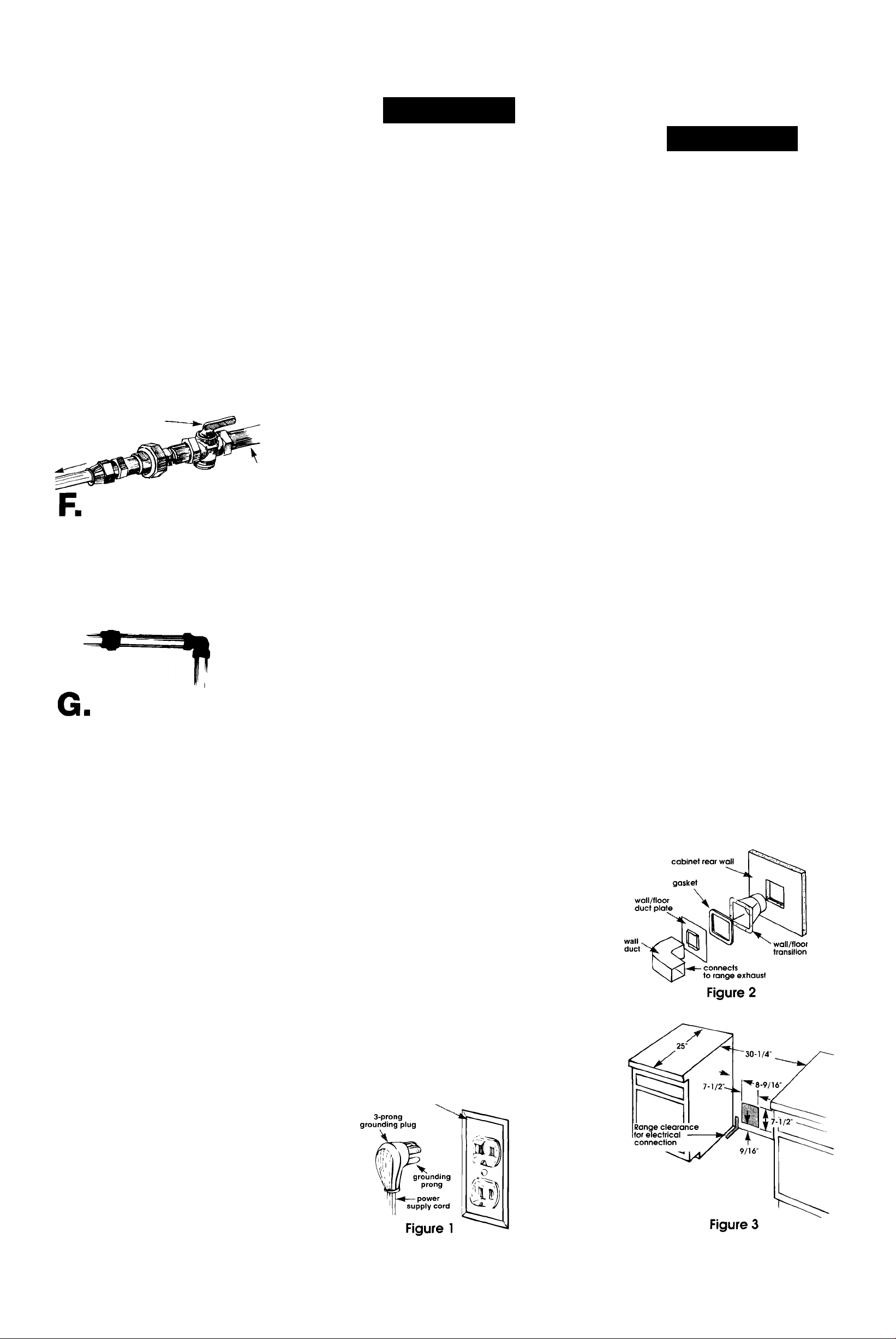
shutoff
valve
to range
gas
supply line
The supply line shall be
equipped with an approved shutoff
valve. This valve should be located in
the same room as the range and
should be in a location that allows
ease of opening and closing. Do Not
block access to shutoff valve.
If rigid pipe is used as a gas
supply line, a combination of pipe
fittings must be used to obtain an in
line connection to the range. All
strains must be removed from the
supply and fuel lines so range will be
level and in line.
Electrical Shock Hazard
• Electrical ground is required on this
appliance.
• If cold water pipe is interrupted by
plastic, non-metallic gaskets or
other insulating materials, Do Not
use for grounding.
• Do Not ground to a gas pipe.
• Do Not modify the power supply
cord plug. If it does not fit the
outlet, have a proper outlet
installed by a qualified electrician.
• Do Not have a fuse in the neutral or
grounding circuit. A fuse in the
neutral or grounding circuit could
result in an electrical shock.
• Do Not use an extension cord with
this appliance.
• Check with a qualified electrician if
you are in doubt as to whether the
appliance is properly grounded.
Failure to follow these instructions
could result in serious injury or death.
If codes permit and a separate
grounding wire is used, it is
recommended that a qualified
electrician determine that the grounding
path is adequate.
A 120-volt, 60-Hz, AC-only, 15-ampere,
fused electrical supply Is required. A
time-delay fuse or circuit breaker Is
recommended. It Is recommended
that a separate circuit serving only this
appliance be provided.
Electronic ignition systems operate
within wide voltage limits, but proper
grounding and polarity are necessary.
In addition to checking that the outlet
provides 120-volt power and is
oorrectly grounded, the outlet must
be checked by a qualified electrician
to see if it is wired with correot polarity.
The wiring diagram is included in the
literature package. The wiring
diagram is also located on the
bottom of the storage drawer.
Recommended
A WARNING
Fire Hazard
• Venting system must terminate to
the outside.
• Do Not terminate the ductwork in
an attic or other enclosed space.
• Do Not use 4” laundry-type wall
caps.
Failure to follow recommended
venting instructions may result in a
fire.
Determine which venting method to
use. Ductwork can extend either
through the rear wall, left side or floor.
All transitions and ductwork needed
to vent to rear of range are supplied
with range. To vent through the floor,
use floor vent kit supplied. To vent to
left side of range, a separate venting
kit (Kit No. 4315772) must be used and
is available from your dealer or
authorized parts distributor.
The length of the ductwork and
number of elbows should be kept to a
minimum to provide efficient
performance. The size of the
ductwork should be uniform. Do Not
install two elbows together. Use duct
tape to seal all joints in the duct
system. Use caulking to seal exterior
wall or floor opening around cap.
Figures 2 - 7 show common venting
methods and types of materials
needed.
Flexible ductwork is Not
recommended. If it is used, calculate
each foot of flexible ductwork as two
feet of straight metal ductwork.
Flexible elbows count twice as much
as standard elbows. Use metal
ductwork only.
Use ductwork cutout dimensions
shown in Figures 2-7. If the ductwork
cutout location falls over a joist or
stud, a supporting frame must be
constructed. Do Not cut joist or stud.
NOTE: Make sure there is proper
clearance within the wall or floor for
exhaust duct before making cutouts.
H
checking the regulator setting is to be
at least 7" W.C.(natural gas).
Maximum supply pressure for Natural
Gas must not exceed 14" W.C. in
accordance with a regulator setting
of 6" W.C.
I
Testing above 1 /2 psi (gauge)
The range and its individual shutoff
valve must be disconnected from the
gas supply piping system during any
pressure testing of that system at test
pressures in excess of 1/2 psig (3.5
kPa).
Testing at 1 /2 psi (gauge)
The range must be isolated from the
gas supply piping system by closing its
individual manual shutoff valve during
any pressure testing of the gas supply
piping system at test pressures equal
to or less than 1/2 psig (3.5 kPa).
The gas supply pressure for
Line pressure testing:
grounding method
For personal safety, this appliance
must be grounded. This appliance is
equipped with a 3-prong grounding
plug. To minimize possible shock
hazard, the cord must be plugged
into a mating 3-prong, groundingtype wall receptacle, grounded in
accordance with the National
Eleotrical Code, ANSI/NFPA 70 —
latest edition*, and all local codes
and ordinances, (See Figure 1.) If a
mating wall receptacle is not
available, it is the personal
responsibility and obligation of the
customer to have a properly
grounded, 3-prong wall receptacle
installed by a qualified electrician.
3-prong
grounding-type
wall receptacle
Rear wall venting installation
Panel B
 Loading...