

Page 1
CONSUMER SERVICES TECHNICAL
EDUCATION GROUP PRESENTS
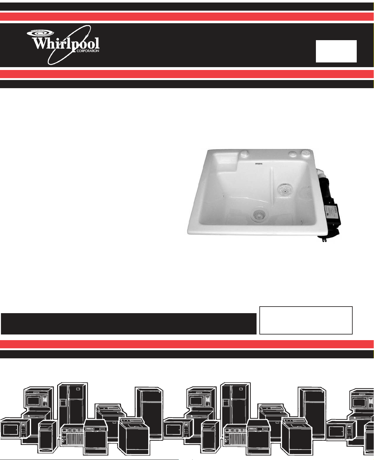
SinkSpa
JETTED SINK
Model LJD1306L
L-71
JOB AID
Part No. 8178201
Page 2

FORWARD
This Whirlpool Job Aid, “SinkSpa Jetted Sink,” (Part No. 8178201), provides the technician with
information on the installation, operation, and service of the SinkSpa Jetted Sink. It is to be used
as a training Job Aid and Service Manual.
The Wiring Diagram used in this Job Aid is typical and should be used for training purposes only.
Always use the Wiring Diagram supplied with the product when servicing the unit.
GOALS AND OBJECTIVES
The goal of this Job Aid is to provide detailed information that will enable the service technician to
properly diagnose malfunctions and repair the SinkSpa Jetted Sink.
The objectives of this Job Aid are to:
• Understand and follow proper safety precautions.
• Successfully troubleshoot and diagnose malfunctions.
• Successfully perform necessary repairs.
• Successfully return the sink to its proper operational status.
WHIRLPOOL CORPORATION assumes no responsibility for any repairs made
on our products by anyone other than Authorized Service Technicians.
Copyright © 2002, Whirlpool Corporation, Benton Harbor, MI 49022
- ii -
Page 3

TABLE OF CONTENTS
Page
GENERAL............................................................................................................................................. 1-1
Safety First ...................................................................................................................................... 1-1
Model & Serial Number Designations ............................................................................................. 1-2
Model & Serial Number Label Location .......................................................................................... 1-3
Specifications .................................................................................................................................. 1-4
Whirlpool SinkSpa Jetted Sink Warranty ....................................................................................... 1-5
INSTALLATION INFORMATION ......................................................................................................... 2-1
Installing The Sink In A Cutout........................................................................................................ 2-1
Mounting The Pop-Up Basket Assembly & Torque Tube ............................................................... 2-1
Installing The 10-Minute Timer ....................................................................................................... 2-4
PRODUCT OPERATION ...................................................................................................................... 3-1
Using The Sink ................................................................................................................................ 3-1
The Speed Control .......................................................................................................................... 3-1
Cleaning The Filter .......................................................................................................................... 3-1
The Timer ........................................................................................................................................ 3-1
Water Flow ...................................................................................................................................... 3-2
COMPONENT ACCESS ....................................................................................................................... 4-1
Removing The Pump Motor & Disassembling The Pump .............................................................. 4-1
Removing The Speed Control......................................................................................................... 4-4
WIRING DIAGRAM .............................................................................................................................. 5-1
- iii-
Page 4

— NOTES —
- iv-
Page 5
GENERAL
SAFETY FIRST
Your safety and the safety of others is very important.
We have provided many important safety messages in this Job Aid and on the appliance. Always
read and obey all safety messages.
This is the safety alert symbol.
This symbol alerts you to hazards that can kill or hurt you and others.
All safety messages will follow the safety alert symbol and either the word
“DANGER” or “WARNING.” These words mean:
You can be killed or seriously injured if you don’t
DANGER
WARNING
All safety messages will tell you what the potential hazard is, tell you how to reduce the chance
of injury, and tell you what can happen if the instructions are not followed.
immediately follow instructions.
You can be killed or seriously injured if you don’t
follow instructions.
ELECTRICAL POWER SUPPLY &
GROUNDING REQUIREMENTS
WARNING
Electrical Shock Hazard
Disconnect power before servicing.
Replace all parts and panels before
operating.
Failure to do so can result in death or
electrical shock.
WARNING
Electrical Shock Hazard
Plug into a grounded 3-prong outlet.
Do not remove ground prong.
Do not use an adapter.
Do not use an extension cord.
Failure to follow these instructions can
result in death, fire, or electrical shock.
1-1
Page 6

MODEL & SERIAL NUMBER DESIGNATIONS
MODEL NUMBER
MODEL NUMBER L J D 13 0 6 L Q 0
INTERNATIONAL SALES IND.
OR MARKETING CHANNEL
IF PRESENT
PRODUCT GROUP:
L = DOMESTIC LAUNDRY
PRODUCT IDENTIFICATION:
J = JETTED SINK
FEATURE CODE 1:
D = 10 MINUTE TIMER
FEATURE CODE 2:
FIRST DIGIT
1 = CYCLES 1 THROUGH 9
SECOND DIGIT
3 = 1 TO 6 WASHER SPEED COMBINATIONS
FEATURE CODE 3:
0 = NO SPINNING AVAILABLE
FEATURE CODE 4:
6 = MANUAL FILL, MAX CAPACITY 9 GALLONS
YEAR OF INTRODUCTION:
L = 2002, M = 2003
COLOR CODE:
Q = WHITE-ON-WHITE
T = BISCUIT-ON-BISCUIT
ENGINEERING CHANGE (NUMERIC)
SERIAL NUMBER
SERIAL NUMBER C M M 04 54321
DIVISION RESPONSIBILITY
C = CLYDE, OH
MANUFACTURING SOURCE
M = MTI WHIRLPOOLS
YEAR OF PRODUCTION:
M = 2002
WEEK OF PRODUCTION:
04 = 4th WEEK
PRODUCT SEQUENCE NUMBER
1-2
Page 7
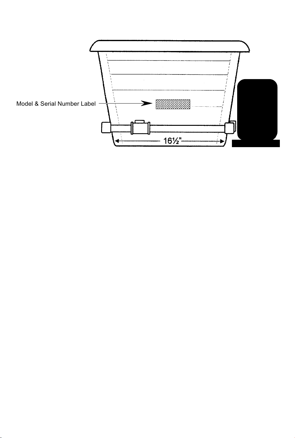
MODEL & SERIAL NUMBER LABEL LOCATION
8
8
8
8
2345678901234567
2345678901234567
Model & Serial Number Label
2345678901234567
2345678901234567
1-3
Page 8
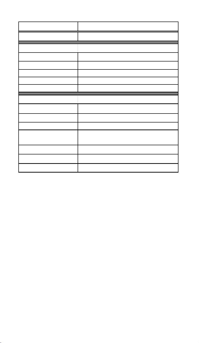
SPECIFICATIONS
Model No. LJD1306LQ & T
Color Q = White, T = Biscuit
Dimensions:
Overall Width Minimum 84cm (33
Sink Width
Depth 56 cm (22
Height 31.7 cm (12.5
Weight 17.2 kg (38 lbs.)
General:
Motor Electrical Rating 120 VAC, 6.5 Ampere
Motor H.P. 1
Sink Material & Texture Acrylic, Glossy
Controls
Drain Set Single Remote Pop-Up Basket
Timer Standard, 10 minute, AC Receptacle-Mount
Warranty 1 Year, Parts & Labor; 5 Years, Sink Shell
Pneumatic On/Off Button, Air Volume
Control Knob With Low-Med-High Settings
63.5 cm (25
″) Cabinet Base
″)
″)
″)
1-4
Page 9

WHIRLPOOL SinkSpa JETTED SINK WARRANTY
LENGTH OF
WARRANTY:
FULL ONE-YEAR
WARRANTY
FROM DATE OF
PURCHASE.
LIMITED 5-YEAR
WARRANTY
FROM DATE OF
PURCHASE.
WHIRLPOOL CORPORATION SHALL NOT BE LIABLE FOR INCIDENTAL OR CONSEQUENTIAL DAMAGES.
Some states or provinces do not allow the exclusion or limitation of incidental or consequential damages, so this
exclusion or limitation may not apply to you. This warranty gives specific legal rights and you may also have other
rights which vary from state to state or province to province.
Outside the United States and Canada, a different warranty may apply. For details, please contact your
authorized Whirlpool dealer.
If you need service, help can be found by checking the “Assistance Or Service” section in the Use and Care Guide,
or by calling the Whirlpool Customer Interaction Center telephone number, 1-800-253-1301, from anywhere in the
U.S.A.
WHIRLPOOL WILL PAY FOR:
FSP® replacement parts and
repair labor costs to correct
defects in materials or workmanship. Service must be
provided by a Whirlpooldesignated service company.
Sink shell replacement. Service
must be provided by a
Whirlpool-designated service
company.
WHIRLPOOL WILL NOT PAY FOR:
A. Service calls to:
1. Correct the installation of the unit.
2. Replace house fuses or correct house
wiring.
3. Replace owner-accessible filters.
B. Repairs when the unit is used in other than
normal, single-family household use.
C. Pickup and delivery. The unit is designed to
be repaired in the home.
D. Damage to the unit caused by accident, al-
teration, misuse, abuse, fire, flood, acts of
God, or use of products not approved by
Whirlpool.
E. Repairs to parts or systems resulting from
unauthorized modifications made to the
unit.
1-5
Page 10

— NOTES —
1-6
Page 11
INSTALLATION INFORMATION
INSTALLING THE SINK
IN A CUTOUT
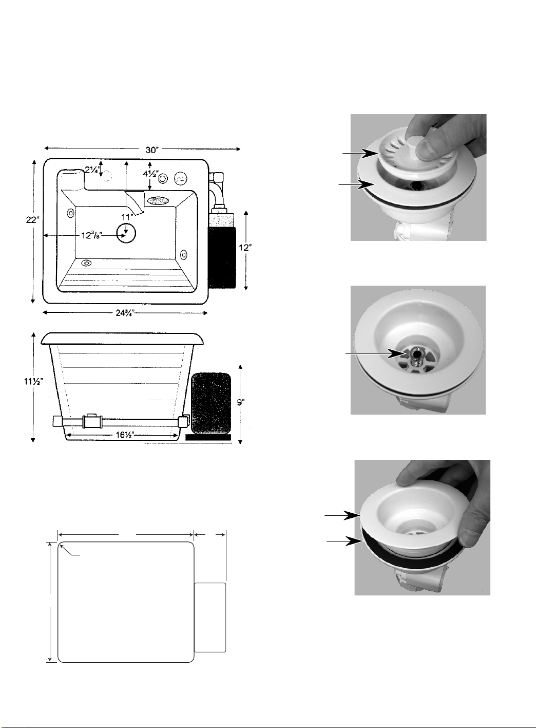
1. Determine the location that you would like
to mount the sink. Also drill any faucet or
accessory holes in the countertop. NOTE:
The sink dimensions are shown below.
MOUNTING THE POP-UP BASKET
ASSEMBLY & TORQUE TUBE
1. Remove the basket strainer from the grating.
Basket
Strainer
Grating
2. Remove the fixing screw from the basket
assembly.
2. Cut a mounting opening for the sink that is
24″ x 21.25″ with 1″ radius corners. Extend the counter top/cabinet on the right
side 6″ to accommodate the pump.
24″ 6″
1″ Radius
21.25″
Pump
Area
Fixing
Screw
3. Remove the grating and rubber gasket
from the basket body.
Grating
Rubber
Gasket
Continued on the next page.
3. Mount the sink in the cabinet cutout.
2-1
Page 12
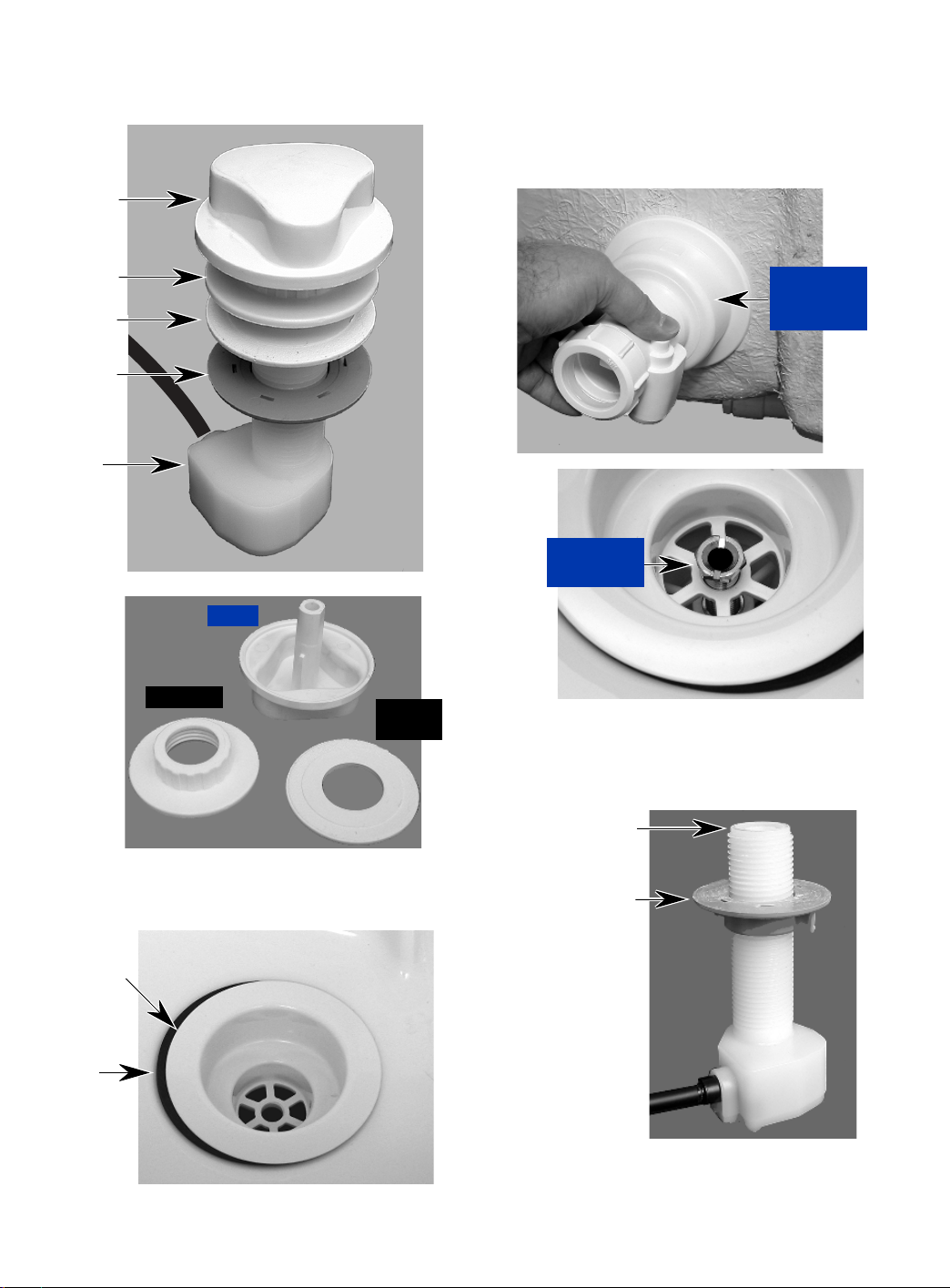
4. Lift the knob off the torque tube.
5. Unscrew the topnut and slide the rubber
seal off the torque tube.
Knob
7. Reach under the sink and place the basket
body below the grating, then mount the
grating to the basket body with the fixing
nut. Keep the rubber gasket centered under the grating, and tighten the nut only
hand tight for now.
Topnut
Rubber
Seal
Locknut
Torque
Tube
Topnut
Knob
Rubber
Seal
Place Basket
Body Against
Grating
Hand Tighten
Fixing Nut
8. Adjust the locknut so the top edge is
approximately 7/8″ from the top of the
torque tube.
6. Place the grating and rubber gasket in the
basket assembly hole in the sink.
Grating
Rubber
Gasket
Adjust Torque
Tube Locknut
7/8″ From Top
2-2
Page 13
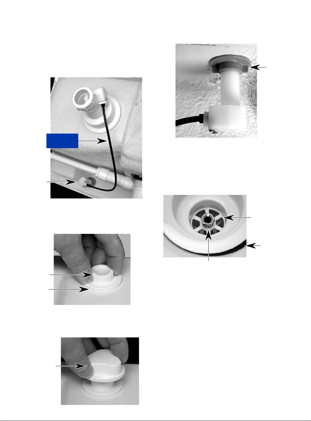
9. Reach under the sink and place the
threaded end of the torque tube up through
the hole in the sink. Rotate the basket
body as necessary, and route the control
cable as shown below. Make sure that
there is no undue strain on the cable
where it enters the torque tube and the
basket body.
Control Cable
Routing
Torque Tube
12. Tighten the locknut against the bottom of
the sink with your fingers as far as possible. It is not necessary to tighten the nut
any further.
Tighten
Locknut
13. Rotate the grating so that three of the six
vanes are aligned with the three vanes in
the basket body. Also make sure that the
rubber gasket is centered below the grating, and does not protrude anywhere.
10. Slide the rubber seal over the end of the
torque tube, and mount and tighten the
topnut against the seal.
Topnut
Rubber
Seal
11. Slide the shaft of the torque knob into the
slot of the torque tube, and push the knob
over the top of the tube.
Install Torque
Knob On Tube
Align Vanes
Keep Gasket
Below Grating
5/8″ Fixing Nut
14. Use a 5/8″ socket and securely tighten the
fixing nut. Use only a moderate amount of
pressure, and do not overtighten the nut.
Continued on the next page.
2-3
Page 14
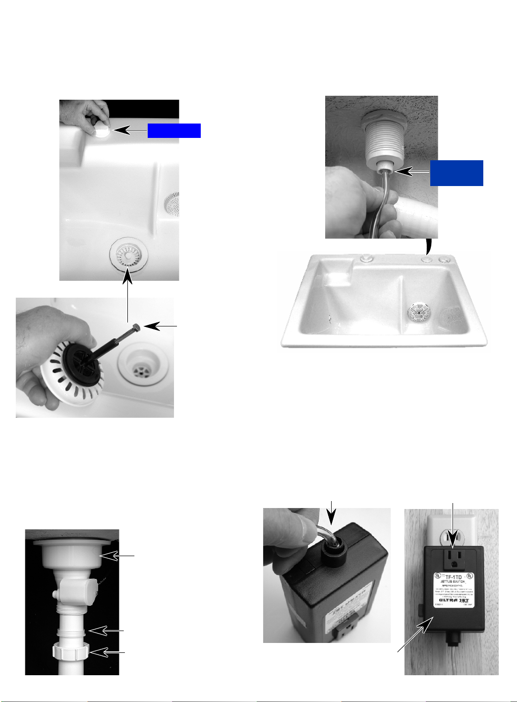
15. Place the basket strainer in the grating
and turn the torque knob to raise and lower
the strainer. The strainer is set to raise
approximately 1/2″. To adjust the height,
turn the adjustment screw in the bottom of
the strainer.
Torque Knob
Basket Strainer
INSTALLING THE
10-MINUTE TIMER
1. Push one end of the plastic tubing over the
small fitting inside the pushbutton as far as
it will go.
Tubing In
Pushbutton
Height
Adjustment
Screw
16. Remove the compression gasket and nut
from the basket body, and install them
over the end of the drain pipe, with the
shoulder of the gasket toward the nut, as
shown below.
17. Insert the end of the drain pipe into the
basket body and hand-tighten the nut.
Basket Body
2. Push the free end of the plastic tubing over
the connector on the timer as far as it will
go. NOTE: If desired, cut the tubing to the
proper length before you connect it.
3. Plug the 10-minute timer into a 120 VAC,
60 Hz wall receptacle. NOTE: The outlet
must be capable of handling up to 15
amps. The pump draws approximately 6.5
amps.
Tubing In Timer
Plug In Pump
Motor Cord Here
Compression Gasket
(Shoulder Toward Nut)
Nut
Plug Timer Into
AC Receptacle
2-4
Page 15
PRODUCT OPERATION
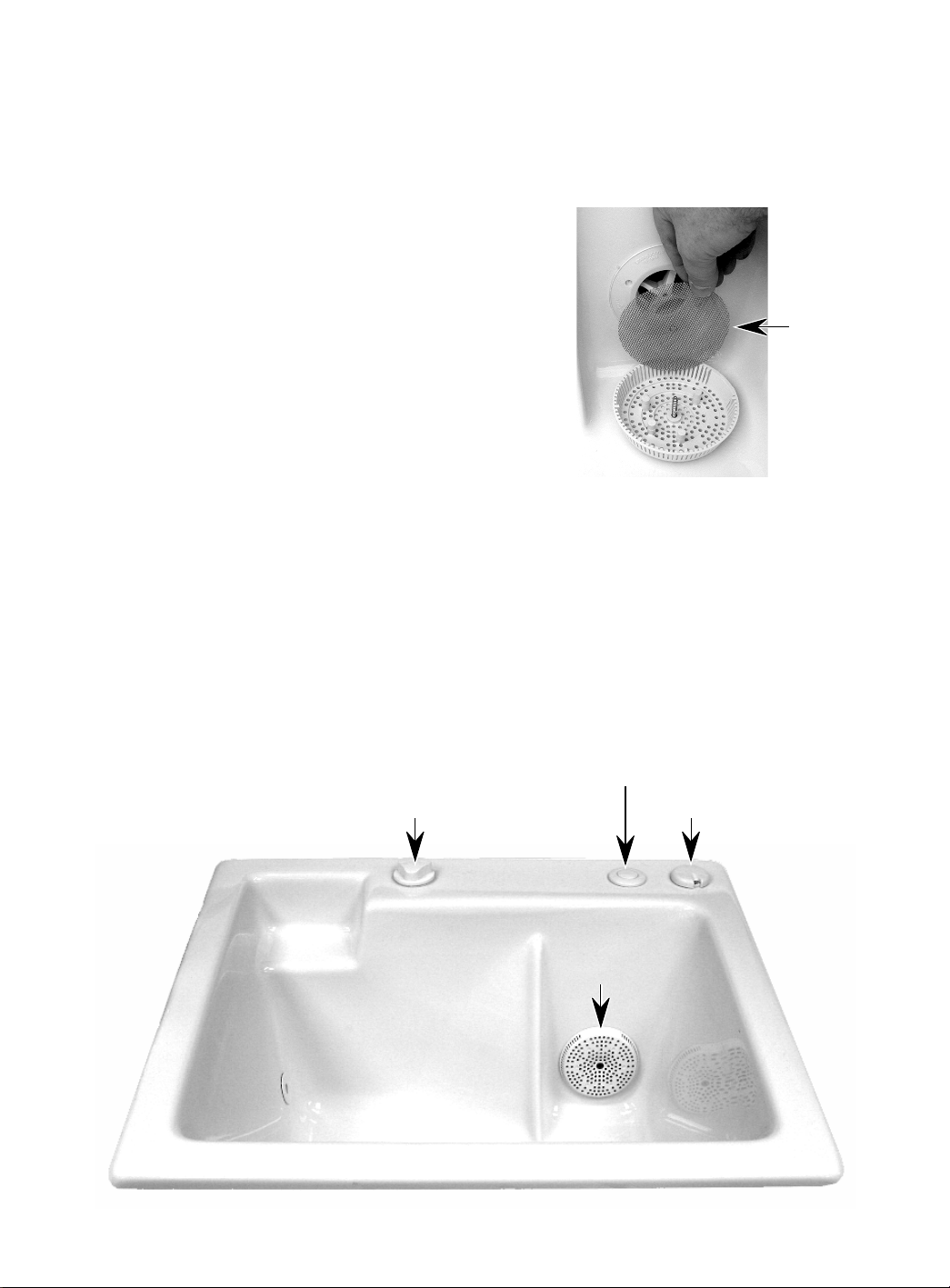
USING THE SINK
1. Turn the torque knob and lower the basket
strainer.
2. Fill the sink with water. IMPORTANT: Do
not operate the pump without water in the
sink, otherwise the pump could be damaged.
3. Press the pneumatic On/Off pushbutton to
turn the pump on. The water in the tub will
begin to circulate.
4. Adjust the Speed Control knob to High,
Medium, or Low, depending on the amount
of circulation desired.
5. Add a low-sudsing detergent, depending
on the load.
6. Place the clothing to be cleaned into the
sink.
THE SPEED CONTROL
The speed control is a 3-position air control that
introduces outside air into the pump return port
to reduce or increase the water flow. The Low
setting increases the air input to reduce water
flow. The higher settings decrease the air input
to increase the water flow.
CLEANING THE FILTER
1. Unscrew the filter cover and remove it.
2. Clean any lint or other debris from the
screen with running water.
Filter Screen
3. Replace the screen and reinstall the cover.
NOTE: Do not overtighten the screw or
you will deform the cover.
THE TIMER
The 10-minute timer is electronically controlled
and is operated by a pneumatic On/Off
pushbutton. If the timer is interrupted during
the 10-minute cycle, pressing the On/Off
pushbutton will begin another 10-minute cycle.
Torque Knob
On/Off Pushbutton
Speed Control
Filter
3-1
Page 16
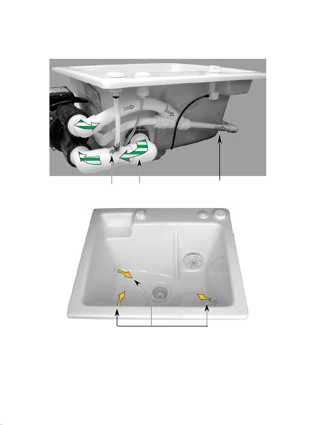
WATER FLOW
Water from the sink is drawn in through the filter
to the inlet port of the pump. Any air from the
speed control is drawn into the pump inlet, as
shown in the photo below. Water is then pumped
out into the tubing that surrounds the sink shell,
and flows through jets into the sink to agitate
the load.
Air From Speed Control
Water Inlet
Circulating Water Into Sink
Water To Jets
3-2
Page 17
COMPONENT ACCESS
REMOVING THE PUMP MOTOR & DISASSEMBLING THE PUMP
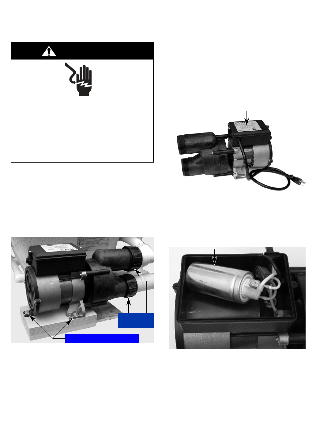
NOTE: When you reconnect the inlet and outlet
WARNING
connectors, hand-tighten them. It is not necessary to use a wrench.
7. To remove the capacitor:
a) Remove the two screws from the cover
and remove the cover.
Electrical Shock Hazard
Disconnect power before servicing.
Replace all parts and panels before
operating.
Failure to do so can result in death or
electrical shock.
1. Disconnect the pump motor power supply
cord from the 10-minute timer.
2. If you do not have enough room under the
sink to access the pump motor, remove
the sink from its mounting location.
3. Remove the two 7/16″ hex-head screws
from the pump motor.
Cover & 2 Screws
b) Disconnect the three wires from the ca-
pacitor terminals. NOTE: The capacitor wiring is shown on page 5-1. Make
sure to connect the wires to the proper
capacitor terminals.
Motor Capacitor
Inlet & Outlet
Connectors
7/16″ Hex-Head Screws
4. Place a container below the pump inlet
and outlet lines to catch the water when
you remove the connectors in the next
step.
5. Remove the inlet and outlet connectors.
6. Remove the pump motor from the mounting platform.
Continued on the next page.
4-1
Page 18
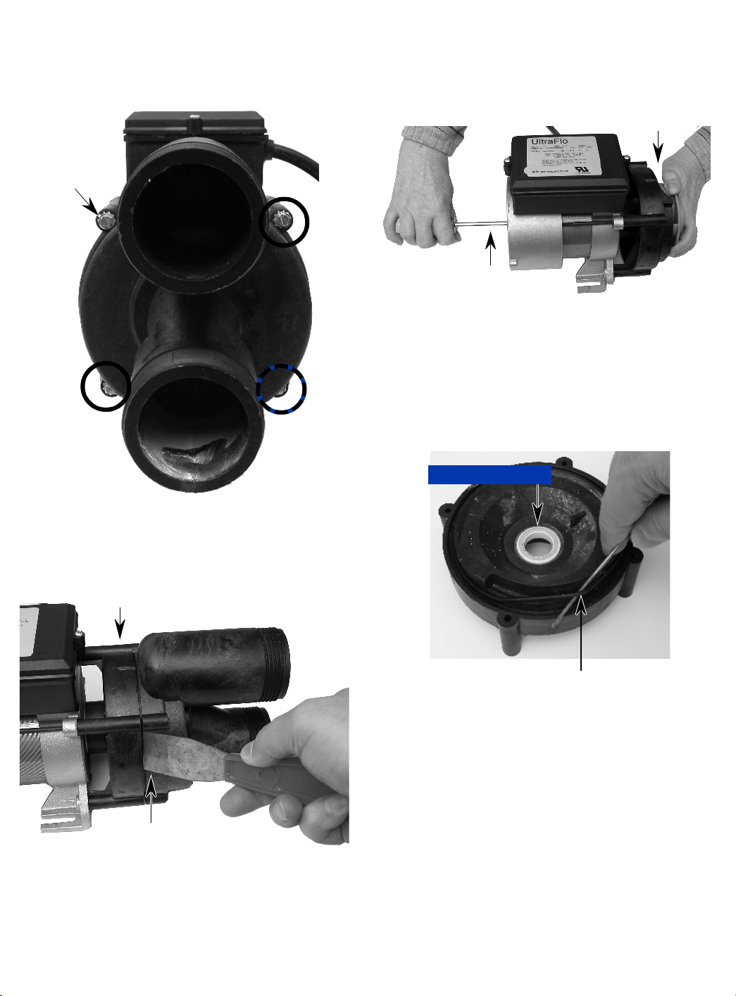
8. To remove the outlet and impeller hous-
ings and rubber o-ring:
a) Remove the four screws and hex nuts
from the outlet housing.
Outlet Housing
Screw (1 of 4)
c) Use a large screwdriver and insert it
into the screw at the front of the housing, then holding the impeller to keep it
from turning, turn the screw, and remove the impeller.
Hold Impeller
Front
Screwdriver
d) Pull the impeller housing off the pump
and position it as shown below.
e) Use a small screwdriver and pry the
o-ring off the impeller housing.
NOTE: If the impeller housing seal is worn,
replace the housing.
b) Use a putty knife and pry the outlet
housing away from the impeller housing, and remove the housing.
Impeller Housing
Pry Outlet Housing
From Impeller Housing
Impeller Housing Seal
Pry O-Ring Off Housing
4-2
Page 19
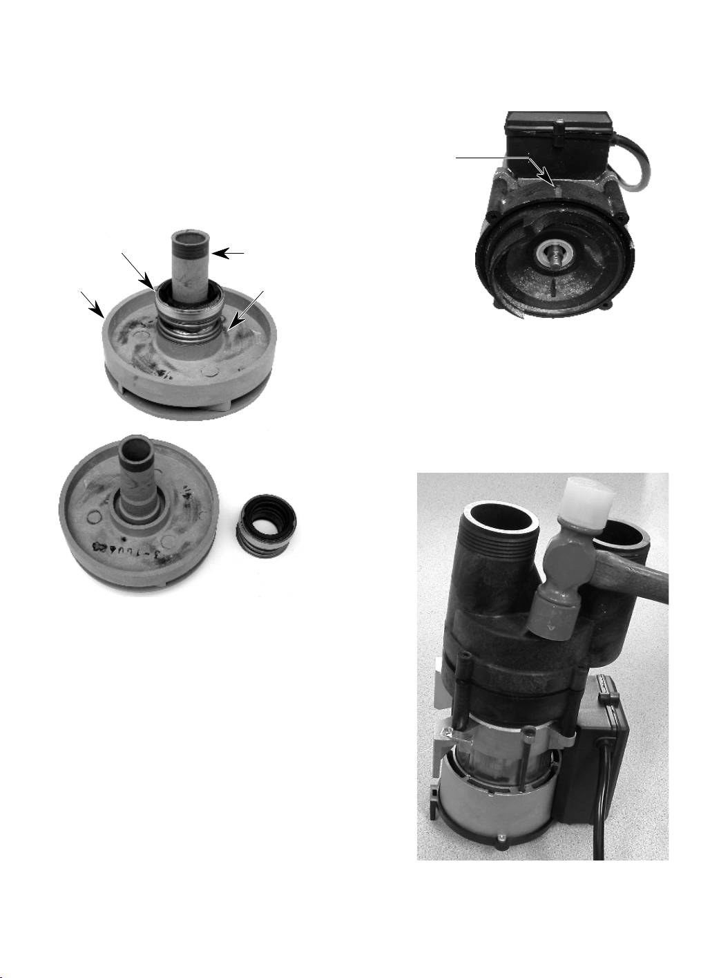
9. To replace the impeller and impeller
seal:
a) Remove the outlet housing and impel-
ler (see steps 8a through 8c).
b) Twist and pull the impeller seal assem-
bly off the impeller shaft. NOTE: When
replacing the impeller seal assembly,
twist it onto the impeller shaft so that
the edge is against the hub of the impeller, as shown.
REASSEMBLY NOTES:
• When you install the impeller housing on the
pump, position the mark on the housing at
the top, as shown below.
Impeller
Housing Mark
Impeller Seal
Assembly
Impeller
Impeller Shaft
Keep Seal
Against Hub
• Position the outlet housing as shown below
so that the four screw holes align. Use a softfaced mallet, and tap the edges of the pump
outlet housing into place on the impeller
housing. Be careful not to strike the outlet
housing too hard, or you could crack it.
4-3
Page 20
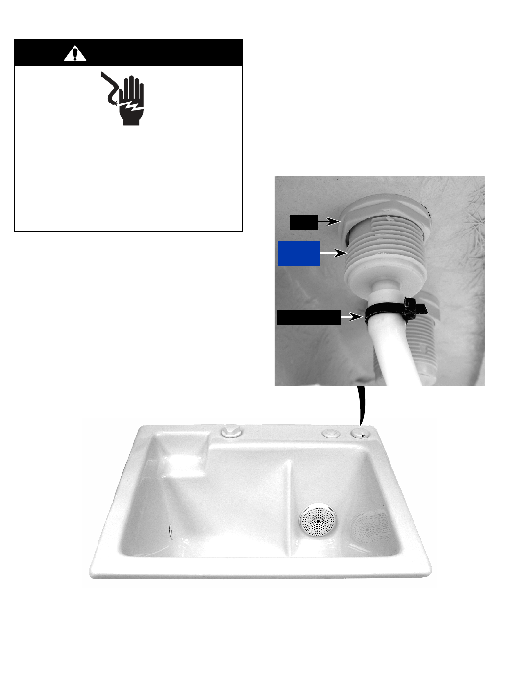
REMOVING THE SPEED CONTROL
WARNING
1. Disconnect the pump motor power supply
cord from the 10-minute timer.
2. If you do not have enough room under the
sink to access the speed control, remove
the sink from its mounting location.
3. Unclamp the tubing at the speed control.
Electrical Shock Hazard
Disconnect power before servicing.
Replace all parts and panels before
operating.
Failure to do so can result in death or
electrical shock.
4. Remove the mounting nut from the speed
control and remove the control from the
sink.
Nut
Speed
Control
Tubing Clamp
4-4
Page 21
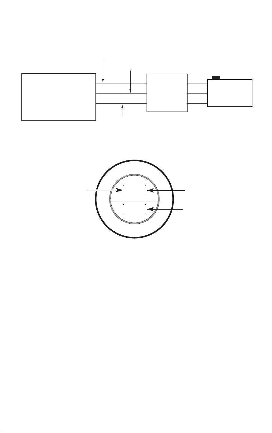
WIRING DIAGRAM
Black (Hot)
White (Neutral)
Grounding Conductor
120 VAC, 60 Hz, 15A
Power Supply
Brn
Motor Capacitor Wiring Diagram
Green (Ground)
8
10-Minute
Timer
(Power Cord)
Pump Motor
Wht
Wht
(Motor)
5-1
Page 22

— NOTES —
5-2
Page 23

PRODUCT SPECIFICATIONS
AND
WARRANTY INFORMATION SOURCES
IN THE UNITED STATES:
FOR PRODUCT SPECIFICATIONS AND WARRANTY INFORMATION CALL:
FOR WHIRLPOOL PRODUCTS: 1-800-253-1301
FOR KITCHENAID PRODUCTS: 1-800-422-1230
FOR ROPER PRODUCTS: 1-800-447-6737
FOR TECHNICAL ASSISTANCE WHILE AT THE CUSTOMER’S HOME CALL:
THE TECHNICAL ASSISTANCE LINE: 1-800-253-2870
HAVE YOUR STORE NUMBER READY TO IDENTIFY YOU AS AN
AUTHORIZED SERVICER
FOR LITERATURE ORDERS:
PHONE: 1-800-851-4605
IN CANADA:
FOR PRODUCT SPECIFICATIONS AND WARRANTY INFORMATION CALL:
1-800-461-5681
FOR TECHNICAL ASSISTANCE WHILE AT THE CUSTOMER’S HOME CALL:
THE TECHNICAL ASSISTANCE LINE: 1-800-488-4791
HAVE YOUR STORE NUMBER READY TO IDENTIFY YOU AS AN
AUTHORIZED SERVICER
Page 24

CORPORATION
 Loading...