


Whirlpool SF368LEPT3, SF368LEPS3, SF368LEPB3 Installation Guide
INSTALLATIONINSTRUCTIONS
30" (76 CM) FREESTANDINGGAS RANGES
Table ofContents
RANGE SAFETY ............................................................................. 1
INSTALLATION REQUIREMENTS ................................................ 2
Tools and Parts ............................................................................ 2
Location Requirements ................................................................ 3
Electrical Requirements ............................................................... 4
Gas Supply Requirements ........................................................... 5
INSTALLATION INSTRUCTIONS .................................................. 6
Unpack Range .............................................................................. 6
Install Anti-Tip Bracket ................................................................. 6
Verify Anti-Tip Bracket Location .................................................. 7
Level Range .................................................................................. 7
RANGESAFETY
Your safety and the safety of others are very important.
We have provided many important safety messages in this manual and on your appliance. Always read and obey all safety
messages.
Make Gas Connection .................................................................. 7
Electronic Ignition System ............................................................ 8
Replace Oven Racks & Storage or Warming Drawer ................ 10
Complete Installation .................................................................. 10
GAS CONVERSIONS .................................................................... 11
LP Gas Conversion .................................................................... 11
Replace Oven Racks & Storage or Warming Drawer ................ 13
Complete Installation .................................................................. 13
Natural Gas Conversion ............................................................. 13
Replace Oven Racks & Storage or Warming Drawer ................ 14
Complete Installation .................................................................. 14
ANTI-TIP BRACKET TEMPLATE ................................................ 16
This is the safety alert symbol.
This symbol alerts you to potential hazards that can kill or hurt you and others.
All safety messages will follow the safety alert symbol and either the word "DANGER" or "WARNING."
These words mean:
You can be killed or seriously injured if you don't immediately
follow instructions.
You can be killed or seriously injured if you don't follow
instructions.
All safety messages will tell you what the potential hazard is, tell you how to reduce the chance of injury, and tell you what can
happen if the instructions are not followed.
A child or adult can tip the range and be killed.
Connect anti-tip bracket to rear range foot.
l___ 1 Tip Over Hazard
Reconnect the anti-tip bracket, if the range is moved.
Failure to follow these instructions can result in death or serious burns to children and adults.
IMPORTANT:
installer: Leave installation instructions with the homeowner.
Homeowner: Keep installation instructions for future reference.
Save installation instructions for local electrical inspector's use.
9758657
I WARNING: For your safety, the information in this manual must be followed to minimize
the risk of fire or explosion, or to prevent property damage, personal injury, or death.
- Do not store or use gasoline or other flammable vapors and liquids in the vicinity of this
or any other appliance.
- WHAT TO DO IF YOU SMELL GAS:
• Do not try to light any appliance.
• Do not touch any electrical switch; do not use any phone in your building.
• Clear the room, building, or area of all occupants.
• Immediately call your gas supplier from a neighbor's phone. Follow the gas supplier's
instructions.
• If you cannot reach your gas supplier, call the fire department.
- Installation and service must be performed by a qualified installer, service agency, or
the gas supplier.
In the State of Massachusetts, the following installation instructions apply:
• Installations and repairs must be performed by a qualified or licensed contractor, plumber, or gasfitter qualified or licensed by
the State of Massachusetts.
• If using a ball valve, it shall be a T-handle type.
• A flexible gas connector, when used, must not exceed 3 feet.
INSTALLATIONREQUIREMENTS
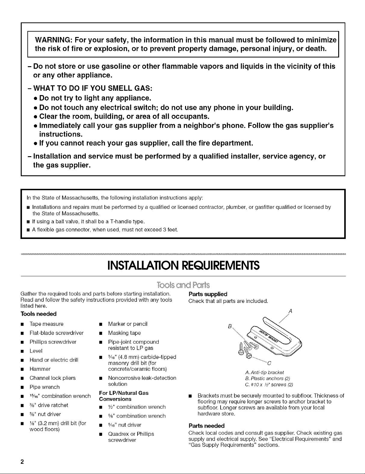
Gather the required tools and parts before starting installation. Parts supplied
Read and follow the safety instructions provided with any tools Check that all parts are included.
listed here.
Tools needed
• Tape measure • Marker or pencil
• Flat-blade screwdriver • Masking tape
• Phillips screwdriver • Pipe-joint compound
• Level
• Hand or electric drill • 3/16"(4.8 mm) carbide-tipped
• Hammer concrete/ceramic floors)
• Channel lock pliers • Noncorrosive leak-detection
• Pipe wrench
• 15/16"combination wrench
• %" drive ratchet • 1/d'combination wrench
• %" nut driver • %" combination wrench
• 1/s"(3.2 mm) drill bit (for • %C nut driver
wood floors)
resistant to LP gas
masonry drill bit (for
solution
For LP/Natural Gas
Conversions
• Quadrex or Phillips
screwdriver
A. Anti-tip bracket
B. Plastic anchors (2)
C. #10x ½"screws (2)
Brackets must be securely mounted to subfloor. Thickness of
flooring may require longer screws to anchor bracket to
subfloor. Longer screws are available from your local
hardware store.
Parts needed
Check local codes and consult gas supplier. Check existing gas
supply and electrical supply. See "Electrical Requirements" and
"Gas Supply Requirements" sections.
IMPORTANT: Observe all governing codes and ordinances. Do
not obstruct flow of combustion and ventilation air.
• It is the installer's responsibility to comply with installation
clearances specified on the model/serial rating plate. The
model/serial rating plate is located on the oven frame behind
the storage drawer panel.
• The range should be located for convenient use in the
kitchen.
• Recessed installations must provide complete enclosure of
the sides and rear of the range.
To eliminate the risk of burns or fire by reaching over heated
surface units, cabinet storage space located above the
surface units should be avoided. If cabinet storage is to be
provided, the risk can be reduced by installing a range hood
that projects horizontally a minimum of 5" (12.7 cm) beyond
the bottom of the cabinets.
• All openings in the wall or floor where range is to be installed
must be sealed.
• Do not seal the range to the side cabinets.
• Cabinet opening dimensions that are shown must be used.
Given dimensions are minimum clearances.
• The floor anti-tip bracket must be installed. To install the anti-
tip bracket shipped with the range, see "Install Anti-Tip
Bracket" section.
• Grounded electrical supply is required. See "Electrical
Requirements" section. Proper gas supply connection must
be available. See "Gas Supply Requirements" section.
• Contact a qualified floor covering installer to check that the
floor covering can withstand at least 200°F (93°C).
• Use an insulated pad or 1/4"(0.64 cm) plywood under range if
installing range over carpeting.
IMPORTANT: Some cabinet and building materials are not
designed to withstand the heat produced by the oven for baking
and self-cleaning. Check with your builder or cabinet supplier to
make sure that the materials used will not discolor, delaminate or
sustain other damage.
4 'I>+..,i _I ..III..,ii I I%,11 _,_
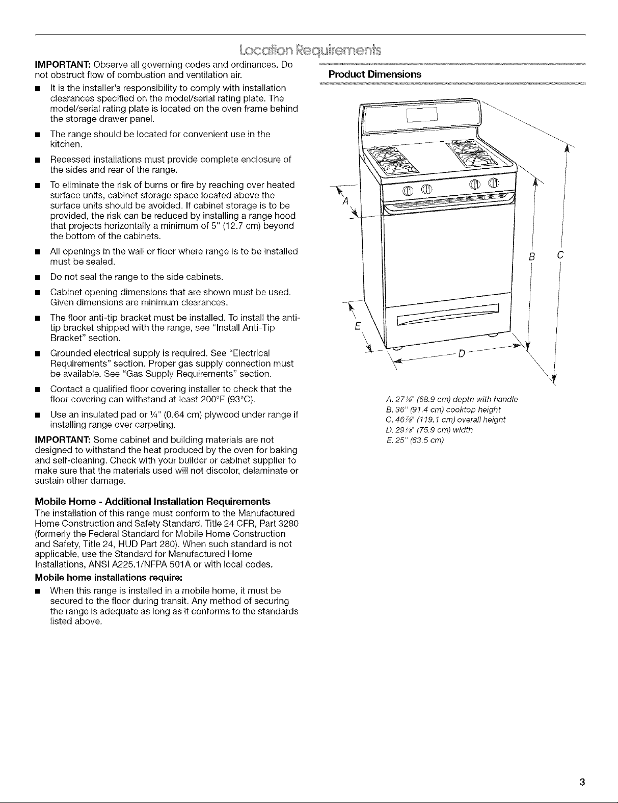
Product Dimensions
©Q O0
E
\
A. 27_" (68.9 crn) depth with handle
B.36" (91.4 cm) cooktop height
C. 46_" (119.1 cm) overafl height
D. 297_'' (75.9 cm) width
E.25" (63.5 cm)
Mobile Home - Additional Installation Requirements
The installation of this range must conform to the Manufactured
Home Construction and Safety Standard, Title 24 CFR, Part 3280
(formerly the Federal Standard for Mobile Home Construction
and Safety, Title 24, HUD Part 280). When such standard is not
applicable, use the Standard for Manufactured Home
Installations, ANSI A225.1/NFPA 501A or with local codes.
Mobile home installations require:
• When this range is installed in a mobile home, it must be
secured to the floor during transit. Any method of securing
the range is adequate as long as it conforms to the standards
listed above.
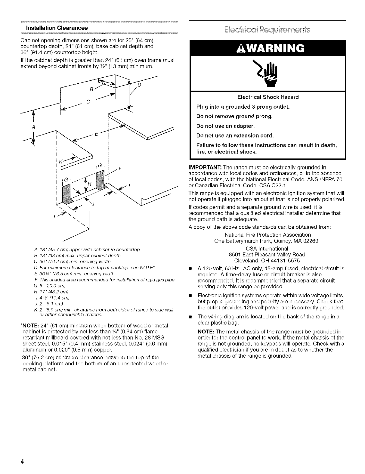
Installation Clearances
Cabinet opening dimensions shown are for 25" (64 cm)
countertop depth, 24" (61 cm), base cabinet depth and
36" (91.4 cm) countertop height.
If the cabinet depth is greater than 24" (61 cm) oven frame must
extend beyond cabinet fronts by 1/2"(13 mm) minimum.
A
J
A. 18" (45.7 cm) upper side cabinet to countertop
B. 13" (33 cm) max. upper cabinet depth
C. 30" (76.2 cm) min. opening width
D. For minimum clearance to top of cooktop, see NOTE*
E.30 _" (76.5 cm) min. opening width
E This shaded area recommended for installation of rigid gas pipe
G. 8" (20.3 cm)
H. 17" (43.2 cm)
I.4½" (11.4 cm)
J. 2" (5.1cm)
K. 2" (5.0 cm) min. clearance from both sides of range to side waft
or other combustible materiaL
*NOTE: 24" (61 cm) minimum when bottom of wood or metal
cabinet is protected by not less than 1/4"(0.64 cm) flame
retardant millboard covered with not less than No. 28 MSG
sheet steel, 0.015" (0.4 mm) stainless steel, 0.024" (0.6 mm)
aluminum or 0.020" (0.5 mm) copper.
30" (76.2 cm) minimum clearance between the top of the
cooking platform and the bottom of an unprotected wood or
metal cabinet.
Electrical Shock Hazard
Plug into a grounded 3 prong outlet.
Do not remove ground prong.
Do not use an adapter,
Do not use an extension cord.
Failure to follow these instructions can result in death,
fire, or electrical shock.
IMPORTANT: The range must be electrically grounded in
accordance with local codes and ordinances, or in the absence
of local codes, with the National Electrical Code, ANSI/NFPA 70
or Canadian Electrical Code, CSA C22.1
This range is equipped with an electronic ignition system that will
not operate if plugged into an outlet that is not properly polarized.
If codes permit and a separate ground wire is used, it is
recommended that a qualified electrical installer determine that
the ground path is adequate.
A copy of the above code standards can be obtained from:
National Fire Protection Association
One Batterymarch Park, Quincy, MA 02269.
CSA International
8501 East Pleasant Valley Road
Cleveland, OH 44131-5575
• A 120 volt, 60 Hz., AC only, 15-amp fused, electrical circuit is
required. A time-delay fuse or circuit breaker is also
recommended. It is recommended that a separate circuit
serving only this range be provided.
• Electronic ignition systems operate within wide voltage limits,
but proper grounding and polarity are necessary. Check that
the outlet provides 120-volt power and is correctly grounded.
• The wiring diagram is located on the back of the range in a
clear plastic bag.
NOTE: The metal chassis of the range must be grounded in
order for the control panel to work. Ifthe metal chassis of the
range is not grounded, no keypads will operate. Check with a
qualified electrician if you are in doubt as to whether the
metal chassis of the range is grounded.
Flexible metal appliance connector:
If local codes permit, a new C.S.A. design-certified,
4 - 5 ft (122 - 152.4 cm) long, 1/2"(1.3 cm) or
3A"(1.9 cm) I.D., flexible metal appliance connector may
be used for connecting range to the gas supply line.
Explosion Hazard
Use a new CSA International approved gas supply line.
Install a shut-off valve.
Securely tighten all gas connections.
if connected to LP, have a qualified person make sure
gas pressure does not exceed 14" (36 cm) water
column.
Examples of a qualified person include:
licensed heating personnel,
authorized gas company personnel, and
authorized service personnel.
Failure to do so can result in death, explosion, or fire.
Observe all governing codes and ordinances.
IMPORTANT: This installation must conform with all local codes
and ordinances. In the absence of local codes, installation must
conform with American National Standard, National Fuel Gas
Code ANSI Z223.1 - latest edition or CAN/CGA B149 - latest
edition.
Type of Gas
Natural Gas:
This range is design-certified by CSA International for use with
Natural gas or, after proper conversion, for use with LP gas.
• This range is factory set for use with Natural gas. See "Gas
Conversions" section. The model/serial rating plate located
on the frame behind the storage drawer has information on
the types of gas that can be used. Ifthe types of gas listed do
not include the type of gas available, check with the local gas
supplier.
LP Gas conversion:
Conversion must be done by a qualified service technician.
No attempt shall be made to convert the appliance from the gas
specified on the model/serial rating plate for use with a different
gas without consulting the serving gas supplier. See "Gas
Conversions" section.
Gas Supply Line
Provide a gas supply line of 3A"(1.9 cm) rigid pipe to the
range location. A smaller size pipe on longer runs may result
in insufficient gas supply. Pipe-joint compounds that resist
the action of LP gas must be used. Do not use TEFLON ®t
tape. With LP gas, piping or tubing size can be r/2" (1.3 cm)
minimum. Usually, LP gas suppliers determine the size and
materials used in the system.
• A 1/2"(1.3 cm) male pipe thread is needed for connection
to the female pipe threads of the inlet to the appliance
pressure regulator.
• Do not kink or damage the flexible metal tubing when
moving the range.
Rigid pipe connection:
The rigid pipe connection requires a combination of pipe
fittings to obtain an in-line connection to the range. The rigid
pipe must be level with the range connection. All strains must
be removed from the supply and fuel lines so range will be
level and in line.
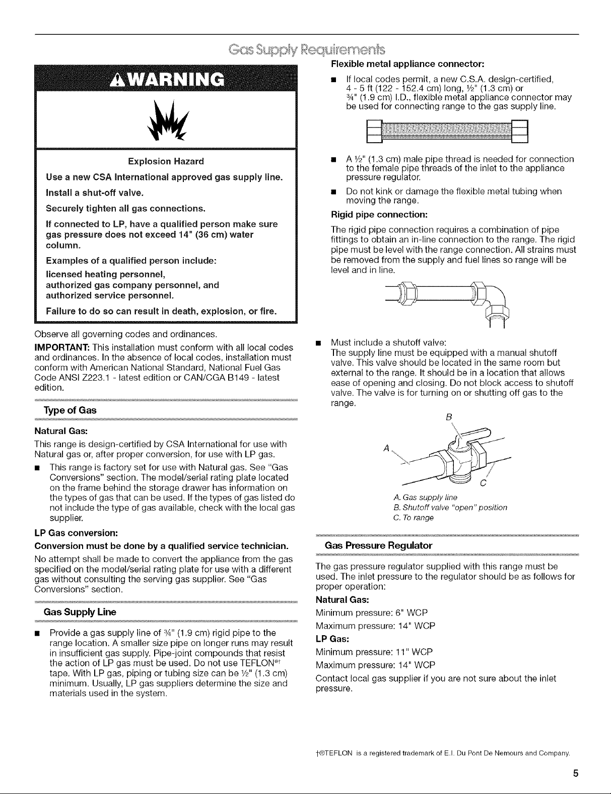
Must include a shutoff valve:
The supply line must be equipped with a manual shutoff
valve. This valve should be located in the same room but
external to the range. It should be in a location that allows
ease of opening and closing. Do not block access to shutoff
valve. The valve is for turning on or shutting off gas to the
range.
B
A
A.Gassupply line
B.Shutoff valve "open" position
C. Torange
Gas Pressure Regulator
The gas pressure regulator supplied with this range must be
used. The inlet pressure to the regulator should be as follows for
proper operation:
Natural Gas:
Minimum pressure: 6" WCP
Maximum pressure: 14" WCP
LP Gas:
Minimum pressure: 11" WCP
Maximum pressure: 14" WCP
Contact local gas supplier if you are not sure about the inlet
pressure.
1-®TEFLON is a registered trademark of E.I. Du Pont De Nemours and Company.