

Whirlpool RS610PXGW, RS675PXGB, RS675PXGQ, RS675PXGT Installation Instructions
INSTALLATION INSTRUCTIONS
30" (76.2 CM) ELECTRIC DROP-IN RANGES
Table of Contents
RANGE SAFETY............................................... 2
INSTALLATION REQUIREMENTS.................. 2
Tools and Parts .............................................2
Location Requirements .................................2
Electrical Requirements ................................4
Countertop Preparation.................................4
INSTALLATION INSTRUCTIONS.................... 5
Prepare Drop-In Range ................................. 5
Remove Oven Trim........................................5
Make Electrical Connection ..........................6
Install Range.................................................. 7
Complete Installation.....................................8
RANGE SAFETY
Your safety and the safety of others are very important.
We have provided many important safety messages in this manual and on your appliance. Always read and obey all safety
messages.
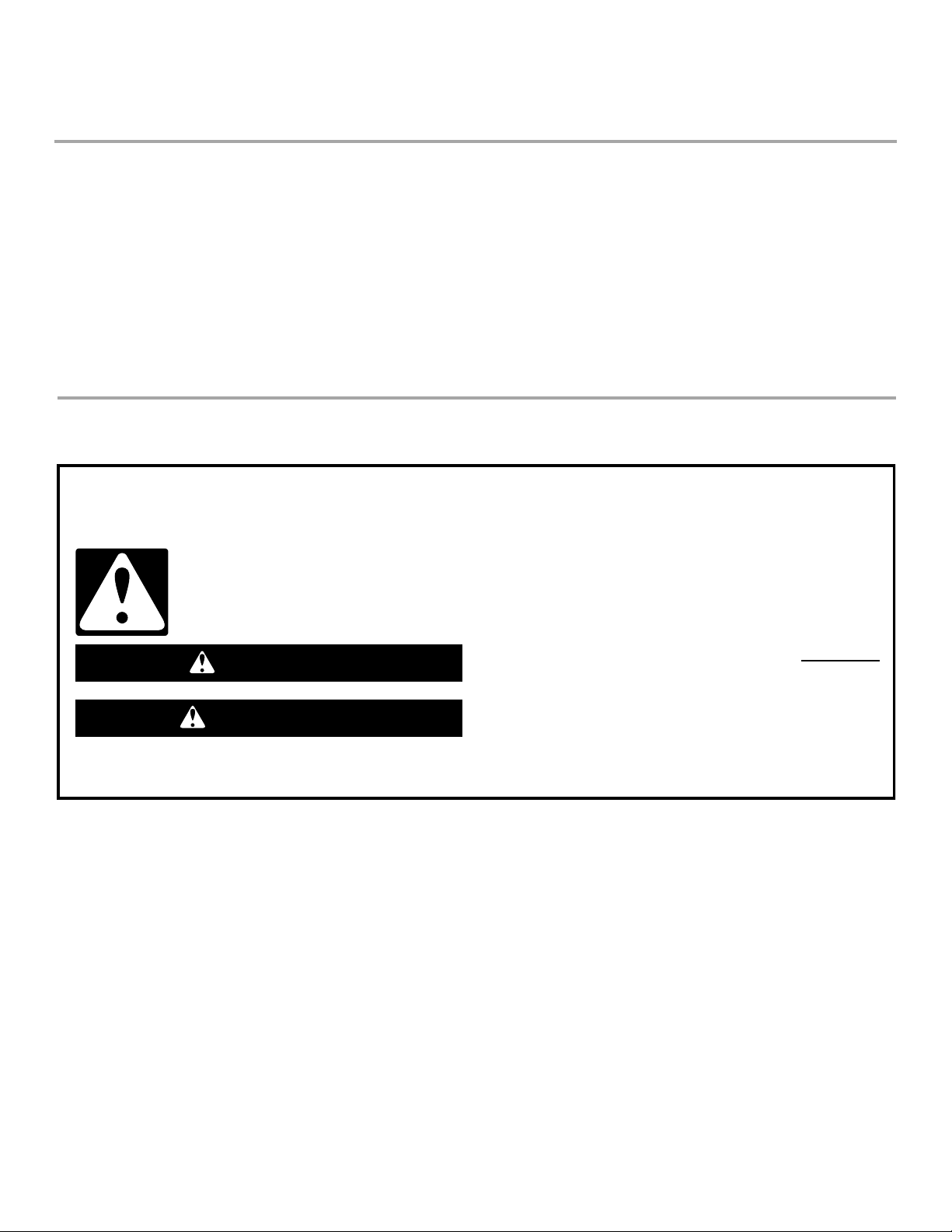
This is the safety alert symbol.
This symbol alerts you to potential hazards that can kill or hurt you and others.
All safety messages will follow the safety alert symbol and either the word “DANGER” or “WARNING.”
These words mean:
You can be killed or seriously injured if you don't immediately
DANGER
WARNING
All safety messages will tell you what the potential hazard is, tell you how to reduce the chance of injury, and tell you what can
happen if the instructions are not followed.
follow instructions.
can be killed or seriously injured if you don't
You
instructions.
follow
IMPORTANT:
Save for local electrical inspector's use.
W10044940
.
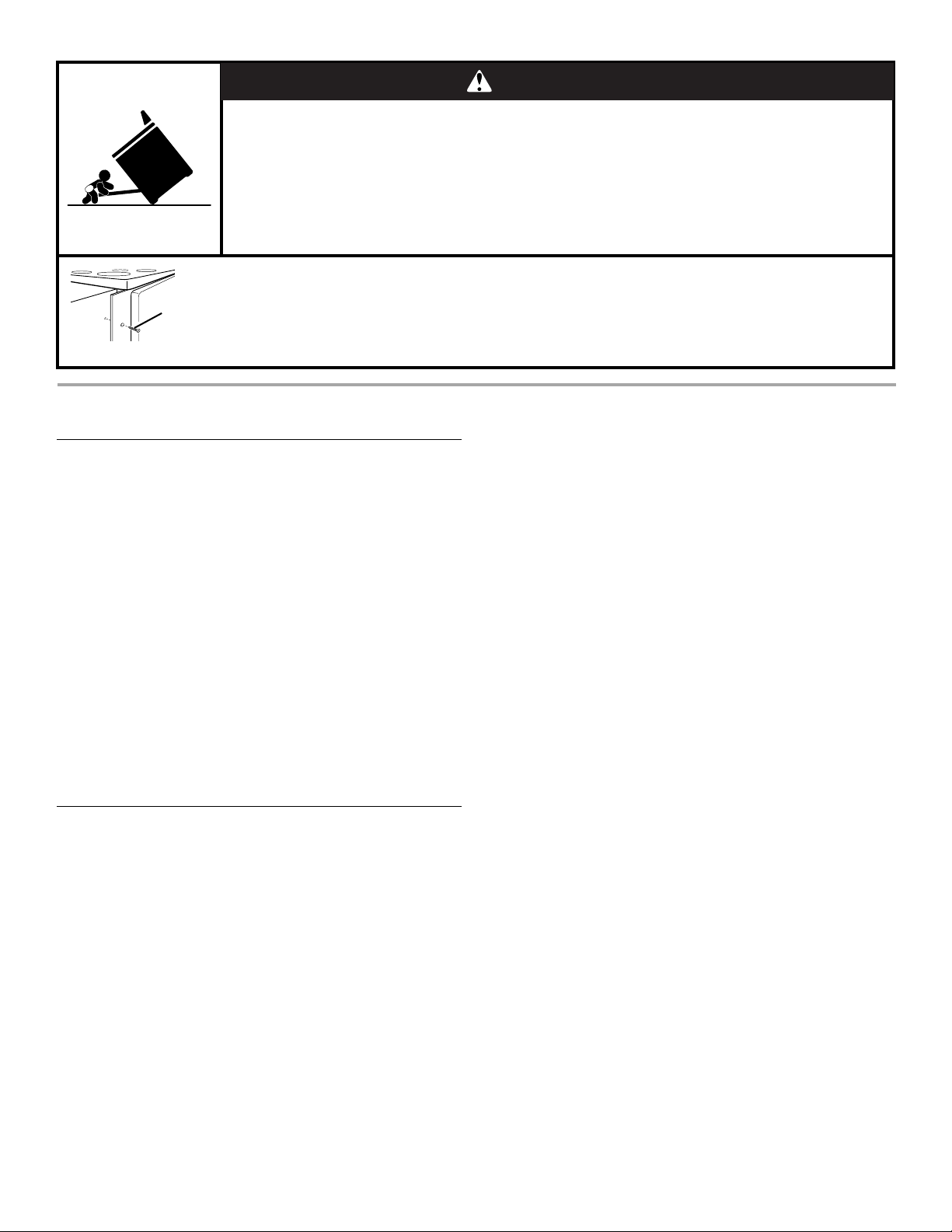
A child or adult can tip the range and be killed.
Securely attach mounting screws to cabinet.
Reattach mounting screws if the range is moved.
See installation instructions for details.
Failure to follow these instructions can result in death or serious burns to children and adults.
Making sure the mounting screws are installed:
Mounting
screw
• Remove side trim from both sides of the range.
• Look for screws securely attached to cabinet.
• Replace side trim.
INSTALLATION REQUIREMENTS
Tools and Parts
Gather the required tools and parts before starting installation.
Read and follow the instructions provided with any tools listed
here.
Tools neede d
■ Phillips screwdriver
■ Router
■ ¹⁄₂" router bit
Parts needed
■ A UL listed or CSA approved conduit connector
■ UL listed wire connects
Parts supplied
■ 2 - #8–14 x 1" screws
Check local codes. Check existing electrical supply. See
“Electrical Requirements.”
It is recommended that all electrical connections be made by a
licensed, qualified electrical installer.
Location Requirements
IMPORTANT: Observe all governing codes and ordinances.
■ It is the installer’s responsibility to comply with installation
clearances specified on the model/serial rating plate. The
model/serial rating plate is located on the right-hand side
oven door trim.
■ Cabinet opening dimensions that are shown must be used.
Given dimensions are minimum clearances.
■ Recessed installation area must provide complete enclosure
around the recessed portion of the range.
■ Measuring tape
■ Level
WARNING
Tip Over Hazard
■ Grounded electrical supply is required. See “Electrical
Requirements” section.
■ Electrical supply junction box should be located on rear wall.
Bottom of junction box should be 30¾" (78.1 cm) max. from
top of countertop.
■ The anti-tip mounting screws must be installed. See “Install
Range” section.
■ The range should be located for convenient use in the kitchen.
■ To eliminate the risk of burns or fire by reaching over heated
surface units, cabinet storage space located above the
surface units should be avoided. If cabinet storage is to be
provided, the risk can be reduced by installing a range hood or
microwave range hood combination that projects horizontally
a minimum of 5" (12.7 cm) beyond the bottom of the cabinets.
■ Range support slats must be solid, level and flush with bottom
of cabinet cutout. Floor must be able to support a weight of
225 lbs (102.0 kg).
Mobile Home - Additional Installation Requirements
The installation of this range must conform to the Manufactured
Home Construction and Safety Standard, Title 24 CFR, Part 3280
(formerly the Federal Standard for Mobile Home Construction and
Safety, Title 24, HUD Part 280). When such standard is not
applicable, use the Standard for Manufactured Home
Installations, ANSI A225.1/NFPA 501A or follow local codes.
Mobile home installations require:
■ When this range is installed in a mobile home, it must be
secured to the floor during transit. Any method of securing the
range is adequate as long as it conforms to the standards
listed above.
■ Four-wire power supply cord or cable must be used in a
mobile home installation. The appliance wiring will need to be
revised. See “Electrical Connection” section.
2
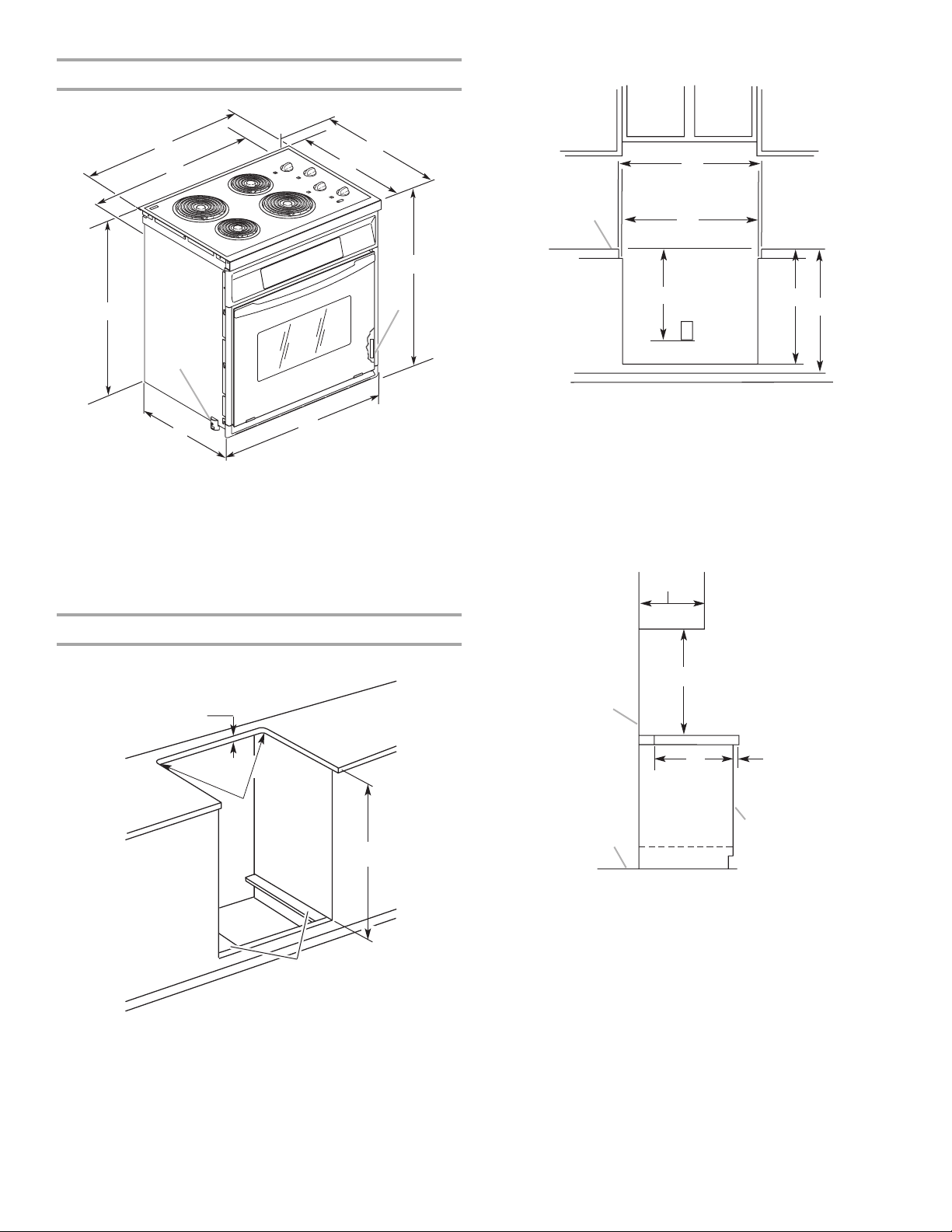
Product Dimensions
Front view of cabinet cutout
B
C
A
J
I
A. 30³⁄₄" (78.1 cm) recessed
height from underside of
cooktop to support slats
B. 28³⁄₈" (72.1 cm) cooktop
recessed width
C. 28⁵⁄₃₂" (71.2 cm) range
recessed width
D. 24¹³⁄₃₂" (58.4 cm) to back of
range
D
E
F
G
H
E. 21" (53.3 cm) cooktop depth
F. 3 1 ¹¹⁄₁₆" (61.1 cm) overall height
G. Model/serial number plate
H. 30" (76.2 cm) overall width
I. 31¹⁄₂" (80.0 cm) overall cooktop
width
J. Shipping foot (temporary)
C
A
A. Top of countertop must be level across front, and front to back.
B. Locate electrical junction box on rear wall. Bottom of junction box
should be 30¾" (78.1 cm) max. from top of countertop.
C. 28½" (72.4 cm) min. opening width
29³⁄₈" (74.6 cm) opening is recommended if available
D. ⁷⁄₈" (1.9 cm) min. required between cutout and cabinet door or hinge
E. 30³⁄₄" (78.1 cm) top of countertop to bottom of front cabinet cutout/
support slats
F. 36" (91.4 cm) overall countertop height
C
B
E
D
F
Side view of cabinet cutout
C
Cabinet Dimensions
Top view of cabinet cutout
A
B
C
D
A. 1¹⁄₂" (3.8 cm) max. countertop thickness
B. ¹⁄₄" (0.6 cm) radius both corners
C. 30³⁄₄" (78.1 cm) top of countertop to support slats
D. 3¹⁄₂" (8.9 cm) wide support slat on each side*
*Slats must be level front to back, as well as with each other.
D
B
G
E
F
A
A. Floor
B. Wall
C. 13" (33.0 cm) max. upper
cabinet depth
D. For minimum clearances to
top of cooktop, see NOTE*
H
E. 1¹⁄₈" (2.9 cm) max.
F. Cabi ne t front
G. 19⁵⁄₈" (49.8 cm)
H. 25" (63.5 cm) countertop depth
24" (61.0cm) lower cabinet depth
*NOTE: 24" (61 cm) minimum when bottom of wood or metal
cabinet is protected by not less than ¹⁄₄" (0.64 cm) flame retardant
millboard covered with not less than No. 28 MSG sheet steel,
0.015" (0.4 mm) stainless steel, 0.024" (0.6 mm) aluminum or
0.020" (0.5 mm) copper.
30" (76.2 cm) minimum clearance between the top of the cooking
platform and the bottom of an unprotected wood or metal
cabinet.
If installing a range hood or microwave hood combination above
the range, follow the range hood or microwave hood combination
installation instructions for dimensional clearances above the
cooktop surface.
3
 Loading...