

Whirlpool RS575PXR5 Installation Instructions Manual
SELF CLEANING SLIDE-IN RANGE
WITH CONVERTIBLE TOP
Part No.560S019P06/816411
INSTALLATION INSTRUCTIONS
Before you begin, read the following instructions
completely and carefully. If followed, they will
simplify the installation job.
IMPORTANT: OBSERVE ALL GOVERNING
CODES AND ORDINANCES
SAVE THESE INSTRUCTIONS FOR THE LOCAL
ELECTRICAL INSPECTOR’S USE.
STEP 1
ELECTRICAL REQUIREMENTS
This appliance may be connected by means of permanent “hard
wiring” or power supply cord kit.
It is the personal responsibility of the customer to contact a
qualified technician to assure that the electrical installation is
adequate and is in conformance with the National Electrical Code
ANSIMPFA 70- latest edition and local codes and ordinances.
THE RANGE MUST BE CONNECTED WITH COPPER WIRE
ONLY. Aluminum wire must not be used to avoid potentially
unsatisfactory connections.
POWER SUPPLY CORD KIT
This appliance must be connected with a power supply cord kit
rated at 125/250 volts minimum, 40 amperes, and marked for use
with ranges. Cord must have three (3) conductors.
For mobile home installation or in areas where local codes do not
permit grounding through neutral, a four (4) conductor power
supply cord kit rated at 125/250 volts minimum, 40 amperes, and
marked for use with ranges shall be used.
Terminalson end of wires must be either closed loop or open-end
spade lugs with upturned ends. Cord must have strain relief
clamp.
MODELS WITH FACTORY-CONNECTED POWER SUPPLY
CORD
Some models may be equipped with a factory-connected, three
(3) conductor, power supply cord.
In mobile home installations or in areas where local codes do not
permit grounding through neutral, a four (4) conductor power
supply cord kit rated at 125/250 volts minimum, 40 amperes and
investigated for use with ranges shall be used. Terminals on end
of wires must be either closed loop or open-end spade lugs with
upturned ends.
STEP 2
ELECTRICAL CONNECTION
WARNING: Disconnect electrical supply before making
electrical connection. Failure to do so may result in
electrical shock or personal injury.
ELECTRICAL GROUND IS REQUIRED ON THIS
APPLIANCE
This appliance is manufactured with the neutral terminal
- connected to the frame.
1.
If local codes permit connection of the frame
grounding conductor to the neutral wire of the copper
power supply cord:
A. Remove the terminal block cover (lowest wire
cover).
B. The terminal nuts are taped to the frame below the
terminal block.
NOTE: Do not loosen factory-installed nuts.
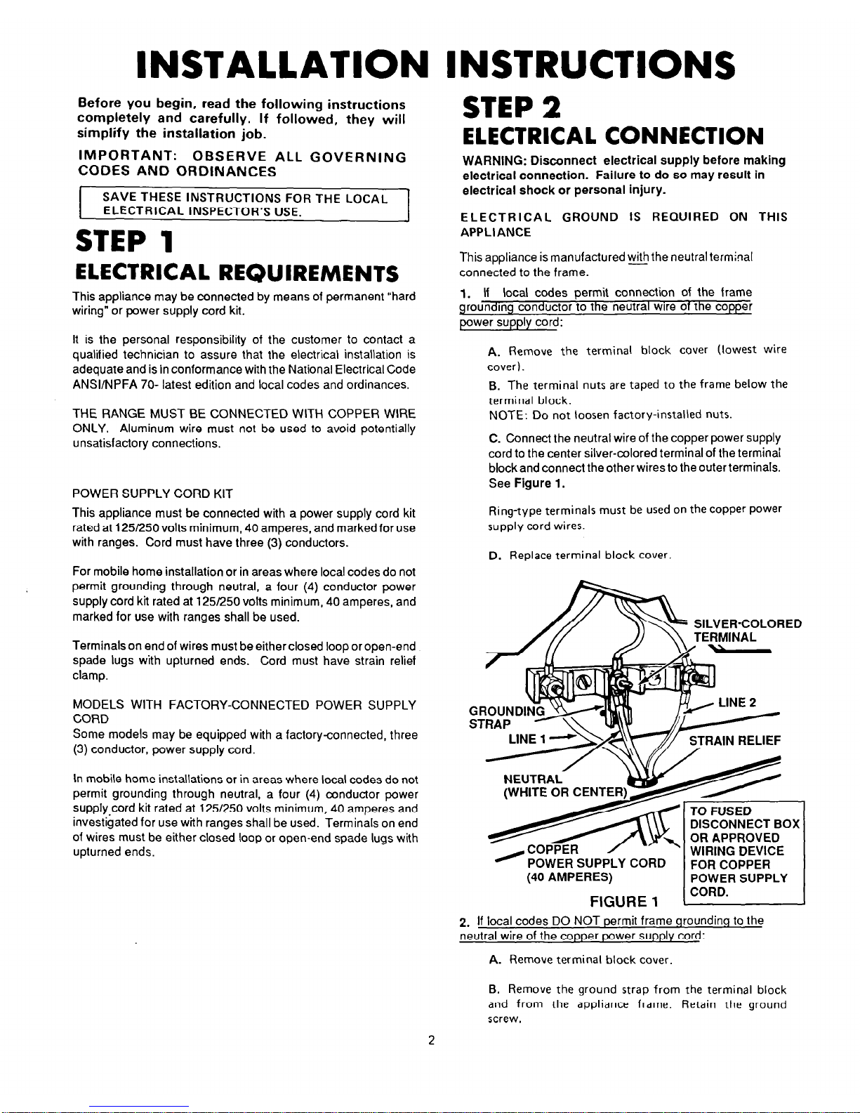
C. Connect the neutral wire of the copper power supply
cord to the center silver-colored terminal of the terminai
block and connect the other wires to the outer terminals.
See Figure I.
Ring-type terminals must be used on the copper power
supply cord wires.
D. Replace terminal block cover.
/D$& SILVER-COLORED
GROUND
STRAP
DISCONNECT BOX
WIRING DEVICE
FOR COPPER
(40 AMPERES)
1 POWER SUPPLY
FIGURE
1
CORD.
2. If local codes DO NOT permit frame qroundinq to the
neutral wire of the copper power supply cord:
A. Remove terminal block cover.
B. Remove
the ground strap from the terminal block
and from the appliance frame. Retain the ground
screw.
2
 Loading...