

Whirlpool RS160LXT, RY160LXT, RS160LXTQ, RY160LXTQ, RS160LXTB User manual
...
CONSUMER SERVICES TECHNICAL
EDUCATION GROUP PRESENTS
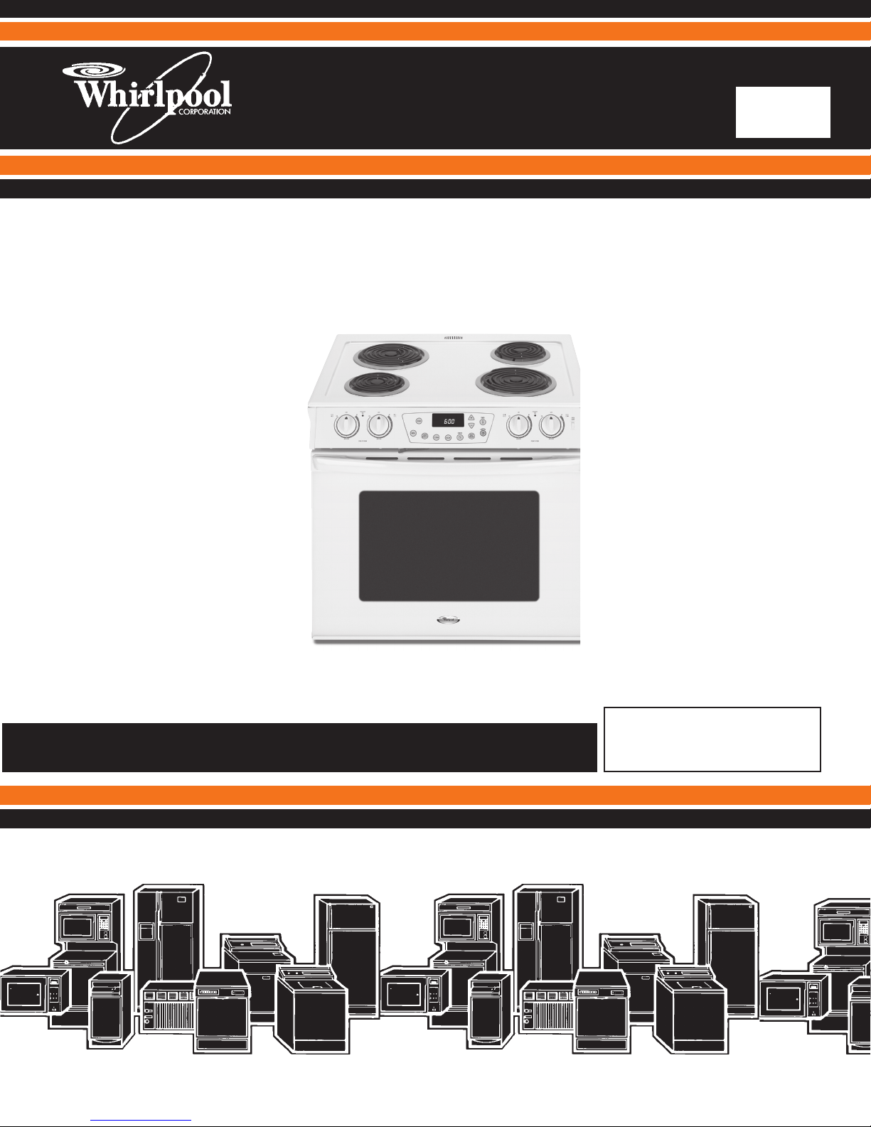
SLIDE-IN ELECTRIC
RANGE
JOB AID
Part No. 8178710
KR-38
Models RS160LXT*, RY160LXT*

FORWARD
This Whirlpool Job Aid “Slide in Electric Range” (Part No. 8178710), provides the In-Home Service
Professional with information on the installation, operation, and service of the Slide in Electric
Range. For specic information on the model being serviced, refer to the “Use and Care Guide,”
or “Wiring Diagram” provided with the cooktop.
The Wiring Diagrams used in this Job Aid are typical and should be used for training purposes
only. Always use the Wiring Diagram supplied with the product when servicing the Slide in Electric
Range.
GOALS AND OBJECTIVES
The goal of this Job Aid is to provide information that will enable the In-Home Service Professional
to properly diagnose malfunctions and repair the Slide in Electric Range.
The objectives of this Job Aid are to:
• Understand and follow proper safety precautions.
• Successfully troubleshoot and diagnose malfunctions.
• Successfully perform necessary repairs.
• Successfully return the Slide in Electric Range to its proper operational status.
WHIRLPOOL CORPORATION assumes no responsibility for any repairs made on
our products by anyone other than authorized In-Home Service Professionals.
Copyright © 2008, Whirlpool Corporation, Benton Harbor, MI 49022
- ii -

TABLE OF CONTENTS
Page
GENERAL .............................................................................................................................. 1-1
Slide in Range Safety......................................................................................................... 1-1
Model & Serial Number Designations ................................................................................ 1-2
Model & Serial Number Label And Wiring Diagram Locations ........................................... 1-3
Specications ..................................................................................................................... 1-4
INSTALLATION INFORMATION ............................................................................................ 2-1
Installation Requirements................................................................................................... 2-1
Location Requirements ...................................................................................................... 2-2
Product Dimensions ........................................................................................................... 2-3
Cabinet Dimensions ........................................................................................................... 2-3
Electrical Requirements ..................................................................................................... 2-4
Installation Instructions....................................................................................................... 2-6
PRODUCT OPERATION ....................................................................................................... 3-1
Display ............................................................................................................................... 3-1
Cancel ................................................................................................................................ 3-1
Clock .................................................................................................................................. 3-1
Control Lock ....................................................................................................................... 3-2
Oven Temperature Control ................................................................................................. 3-2
COMPONENT ACCESS ................................................................................................... 4-1
Component Locations ........................................................................................................ 4-1
Removing The EOC Assembly ........................................................................................... 4-2
Removing An LED and Innite Switch................................................................................ 4-3
Removing Cooktop and Coil Element Receptacles ........................................................... 4-4
Removing Rear Panel ........................................................................................................ 4-6
Removing A Cooling Fan And Oven Light Socket .............................................................. 4-7
Removing Broil Element..................................................................................................... 4-8
Removing Bake Element.................................................................................................... 4-9
Removing The Oven Temperature Sensor ....................................................................... 4-10
Removing The Oven TOC .................................................................................................4-11
Removing Door Latch Assembly ...................................................................................... 4-12
Removing And Reinstalling The Oven Door ..................................................................... 4-14
Removing An Oven Hinge ................................................................................................ 4-15
Removing The Decorative Glass, Oven Door Handle And The Oven Door Glass ........... 4-16
Removing Oven Door Seal .............................................................................................. 4-18
- iii -

COMPONENT TESTING ........................................................................................................ 5-1
Innite Switch ..................................................................................................................... 5-1
Oven Temperature Sensor ................................................................................................. 5-2
Oven TOD .......................................................................................................................... 5-2
Bake Element ..................................................................................................................... 5-3
6 Inch & 8 Inch Coil Elements ............................................................................................ 5-3
Broil Element ...................................................................................................................... 5-4
Cooling Fan Motor.............................................................................................................. 5-4
Door Latch Assembly Switch.............................................................................................. 5-5
DIAGNOSTICS & TROUBLESHOOTING ............................................................................. 6-1
Error Codes ........................................................................................................................ 6-1
"Quick Test" Mode for Electronic Range Control ................................................................ 6-4
Hidden Functions ............................................................................................................... 6-5
WIRING DIAGRAMS ............................................................................................................. 7-1
Cooktop Control Circuit ...................................................................................................... 7-2
Oven Control Circuit ........................................................................................................... 7-2
- iv -
GENERAL
DANGER
WARNING
SLIDE-RANGE SAFETY
Your safety and the safety of others are very important.
We have provided many important safety messages in this manual and on the appliance.
Always read and obey all safety messages.
This is the safety alert symbol.
This symbol alerts you to potential hazards that can kill or hurt you and others.
All safety messages will follow the safety alert symbol and either the word
“DANGER” or “WARNING.” These words mean:
You can be killed or seriously injured if you don’t
immediately follow instructions.
You can be killed or seriously injured if you don’t
follow instructions.
All safety messages will tell you what the potential hazard is, tell you how to reduce the chance
of injury, and tell you what can happen if the instructions are not followed.
1-1

MODEL & SERIAL NUMBER DESIGNATIONS
MODEL NUMBER R Y 1 6 0 L X T W 0
PRODUCT IDENTIFICATION
R = ELECTRIC RANGES
S = GAS RANGES
G = WHIRLPOOL GOLD
PRODUCT IDENTIFICATION
A = ACCESSORY K = KITS
B = BUILT-IN M = MV COMBO
C = COOK TOP S = SET-IN
E = EYE-LEVEL W = GAS SLIDE-IN
F = FREE-STANDING Y = ELEC SLIDE-IN
MODEL SIZE
0 = 20" OR 24" FREE-STANDING
1 = 24" OR 27" BUILT-IN OVEN (BEFORE 1996)
1 = 30" IMPERIAL SERIES FREESTANDING
(1996 AND LATER)|
2 = 30" BUILT-IN OVEN (BEFORE 1996)
2 = 30" FREE-STANDING(1996 AND LATER)
3 = 30" FREE-STANDING
4 = 40" FREE-STANDING
5 = 36" FREE-STANDING
6 = 30" SET-IN RANGES
OVEN TYPE (DOES NOT APPLY TO COUNTERTOPS)
0 THRU 3 = STANDARD PORCELAIN
2 THRU 5 = CONTINUOUS CLEAN (BEFORE 1996)
4 THRU 9 = PYROLYTIC SELF-CLEAN
FE ATURE/ VARI AT I O NS
ELECTRIC
0,1,2,5,7 = COIL ELEMENTS
DOOR TYPE
B = SOLID BLACK GLASS 0 = METAL OVEN DOOR
L = LARGE WINDOW P = STANDARD WINDOW GLASS
FEATURE CODE
E = ELECTRONIC IGNITION (GAS ONLY) X = NOT DEFINED
S = STANDING IGNITION (GAS ONLY)
C = COLOR COORDINATED GLASS (BEFORE 1998)
YEAR OF INTRODUCTION
T = 2007
COLOR CODE
W = White
ENGINEERING CHANGE (NUMERIC)
SERIAL NUMBER FM U 24 01234
DIVISION RESPONSIBILITY
FM = CLEVELAND
YEAR OF PRODUCTION
U = 2007
WEEK OF PRODUCTION
24 = 24TH WEEK
PRODUCT SEQUENCE NUMBER
1-2
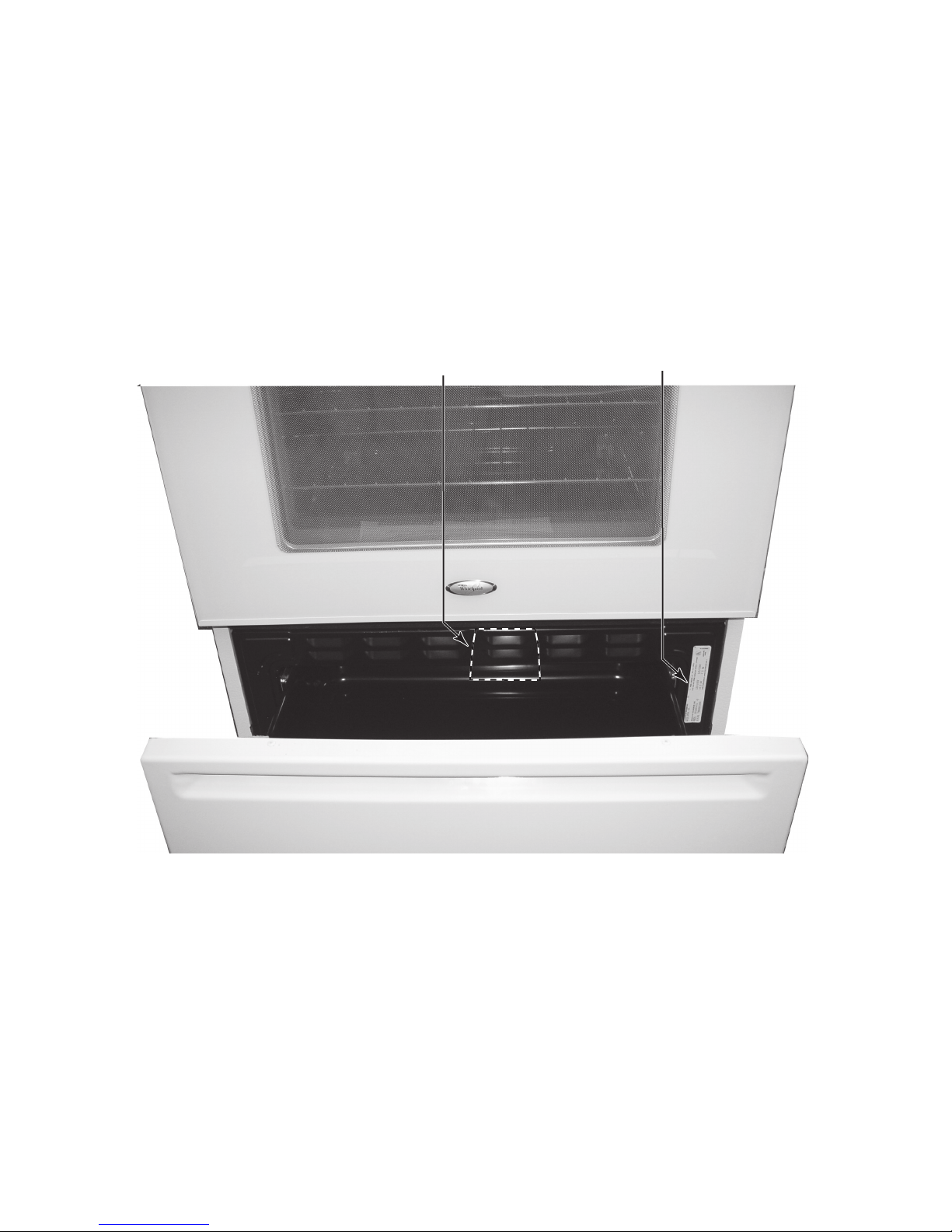
MODEL & SERIAL NUMBER LABEL
AND WIRING DIAGRAM LOCATIONS
The Model/Serial Number label and Wiring Diagram locations are shown below.
Wiring Diagram Location
(On Back Side Of Storage Drawer)
Model & Serial Number
Label Location
1-3
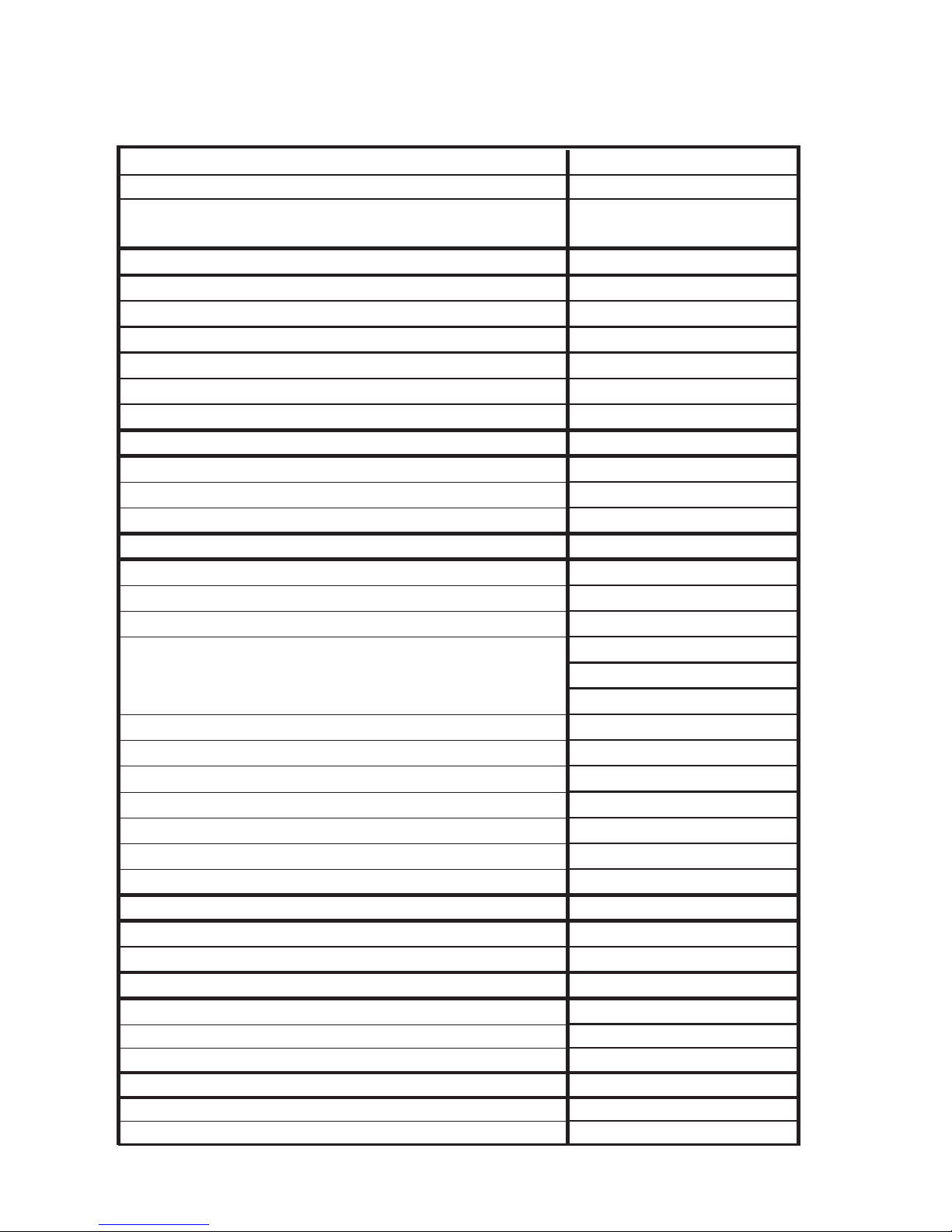
SPECIFICATIONS
RS160LXT, RY160LXT
Color Q (wht), B (Blk), S (SS)
Slide-In
30” Electric Coil, Pyro
COOKTOP
lioCecafruS gnikooC
4stnemelE fo rebmuN
emorhC slwoB pirD
FL ,RR)nrut 3( lioC "6
RL ,FR)nruT 4( lioC "8
2sthgiL rotacidnI
Controls
DELyalpsiD fo epyT
1remiT nehctiK
seYtuO kcoL lortnoC
OVEN
naelC fleSnaelC fo epyT
seYnaelC yaleD
oNnoitcevnoC
seYedoM htabbaS
seYmraW peeK
seYdloH & kooC
launaMmsinahceM kcoL rooD
oNgniliorb rood desolC
seYtnemele liorB desseceR
6sessaP fo rebmuN tnemelE liorB
oNdedulcnI naP liorB
launaMthgiL
nevO
Oven light type
Incandescent
Control Panel
4sbonK fo rebmuN
rekcoRhctiwS thgiL nevO
DOOR
dtSwodniW
SS no SS/ssalGhsiniF
seYsselemarF
Drawer
seYrewarD egarotS
tniaPhsiniF rewarD egarotS
Model
Model Description
1-4

INSTALLATION INFORMATION
INSTALLATION REQUIREMENTS
Tools and Parts
Gather the required tools and parts before starting installation. Read and follow the instructions
provided with any tools listed here.
Tools Needed
Tape measure•
Level•
Phillips screwdriver•
Flat-blade screwdriver•
Wrench or pliers•
3/8" nut driver•
Hand or electric drill•
1/8" (3.2 mm) drill bit•
Parts supplied
Check that all parts are included.
3 - 10–32 hex nuts (attached to terminal •
block)
3 - Terminal lugs•
2 - Oven racks•
2 - #12 x 1 5/8" screws (for mounting anti-tip •
bracket)
Anti-tip bracket (taped inside storage draw-•
er)
Anti-tip brackets must be securely mounted
toback wall or oor.Thickness of oor may
require longer screws to anchor
brackettosub-oor.Longerscrewsareavailable from your local hardware store.
Parts needed
If using a power supply cord:
A UL listed power supply cord kit marked for •
use with ranges.
The cord should be rated at 250 volts minimum,
40 amps or 50 amps that is marked for use with
nominal 1 3/8" (3.5 cm) diameter connection
opening and must end in ring terminals or open end spade terminals with upturned ends.
A UL listed strain relief.•
Check local codes. Check existing electrical
supply. See “Electrical Requirements” on page
2-5. It is recommended that all electrical connections should be made by a licensed, quali-
edelectricalinstaller.
2-1

Location Requirements
IMPORTANT: Observe all governing codes
and ordinances.
It is the installer’s responsibility to comply •
withinstallationclearancesspeciedonthe
model/serial rating plate. The model/serial
rating plate is located on the right-hand side
of the oven frame behind the storage drawer
panel.
The range should be located for convenient •
use in the kitchen.
Toeliminatetheriskofburnsorrebyreach-•
ing over heated surface units, cabinet storage space located above the surface units
should be avoided. If cabinet storage is to be
provided, the risk can be reduced by installing a range hood that projects horizontally a
minimum of 5" (12.7 cm) beyond the bottom
of the cabinets.
Cabinet opening dimensions that are shown •
must be used. Given dimensions are minimum
clearances.
Theooranti-tipbracketmustbeinstalled.•
To install the antitip bracket shipped with
the range, see “Install Anti-Tip Bracket”
section.
Grounded electrical supply is required. See •
“Electrical Requirements” section.
IMPORTANT: To avoid damage to your cabinets, check with your builder or cabinet supplier
to make sure that the materials used will not discolor, delaminate or sustain other damage. This
oven has been designed in accordance with the
requirements of UL and CSA International and
complies with the maximum allowable wood
cabinet temperatures of 194°F (90°C).
Mobile Home - Additional Installation Requirements
Mobile home installations require:
When this range is installed in a mobile •
home,itmustbesecuredtotheoorduring
transit. Any method of securing the range
is adequate as long as it conforms to the
standards listed above.
Four-wire power supply cord or cable must •
be used in a mobile home installation. The
appliance wiring will need to be revised. See
“Electrical Connection” on page 2-5.
The installation of this range must conform
to the Manufactured Home Construction and
Safety Standard, Title 24 CFR, Part 3280 (formerly the Federal Standard for Mobile Home
Construction and Safety, Title 24, HUD Part
280). When such standard is not applicable, the
Standard for Manufactured Home Installations,
ANSI A225.1/NFPA 501A or with local codes.
2-2
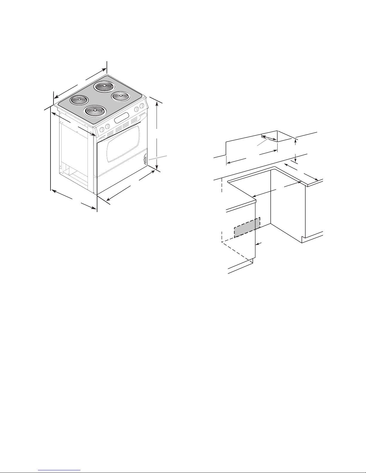
Product Dimensions
A. " (78 cm)
B. 35 " (90.8 cm) height to underside
of cooktop edge with leveling legs
screwed all the way in*
C. Model/serial number plate (located
behind the storage drawer on the
right-hand side of the oven frame
D. 29 " (75.9 cm)
E. 28 " (75.9 cm) from
handle to stando at back
of range**
F. 23 " (60.3 cm)
countertop notch to rear
of cooktop
C
B*
A
D
E**
F
A. 13" (33 cm) upper cabinet
depth
B. 30" (76.2 cm) min. opening
width
C. For minimum clearance to the
top of the cooktop,
see NOTE*.
D. 23 " (58.1 cm) opening
depth
E. 30" (76.2 cm) min. opening
width
F. Junction box - 5.5" (14 cm)
min. from either cabinet,
10" (25.4 cm) max. from oor
Outlet must be ush.
Nothing located in shaded
area can extend more than
2" (5.1 cm) from wall or range
will not slide all the way back.
G. Cabinet door or hinge should
not extend into cutout.
A
B
C
D
E
F
G
Cabinet Dimensions
Cabinet opening dimensions shown are for 25"
(64 cm) countertop depth, 24" (61 cm) base
cabinet depth and 36" (91.4 cm) countertop
height.
If installing a range hood or microwave hood
combination above the range, follow the range
hood or microwave hood combination installation instructions for dimensional clearances
above the cooktop surface.
*Range can be raised approximately 1" (2.5
cm) by adjusting the leveling legs.
**When installed in a 24" (61 cm) base cabinet
with 25" (63.5 cm) countertop; front of oven
door protrudes 2 1/2" (6.4 cm) beyond 24" (61
cm) base cabinet.
NOTE: 24" (61 cm) minimum when bottom of
wood or metal cabinet is protected by not less
than1/4"(0.64cm)ame retardantmillboard
covered with not less than No. 28 MSG sheet
steel, 0.015" (0.4 mm) stainless steel, 0.024" (0.6
mm) aluminum or 0.020" (0.5 mm) copper.
30" (76.2 cm) minimum clearance between the
top of the cooking platform and the bottom of
an unprotected wood or metal cabinet
2-3

Electrical Requirements
If codes permit and a separate ground wire is
used,itisrecommendedthataqualiedelectrical installer determine that the ground path
is adequate and wire gauge is in accordance
with local codes.
Do not use an extension cord.
Be sure that the electrical connection and wire
size are adequate and in conformance with the
National Electrical Code, ANSI/ NFPA 70-latest
edition and all local codes and ordinances.
Allow 2 to 3 ft (61.0 cm to 91.4 cm) of slack •
in the line so that the range can be moved if
servicing is ever necessary.
A UL listed conduit connector must be pro-•
vided at each end of the power supply cable
(at the range and at the junction box).
Wire sizes and connections must conform •
with the rating of the range (40 amps).
The wiring diagram is located on the un-•
derside of the storage drawer or below the
warming drawer in a clear plastic bag.
If using a power supply cord:
A copy of the above code standards can be
obtained from:
National Fire Protection Association
One Battery march Park
Quincy, MA 02269
Electrical Connection
To properly install your range, you must determine the type of electrical connection you will
be using and follow the instructions provided
for it here.
Range must be connected to the proper •
electricalvoltageandfrequencyasspecied
on the model/serial number rating plate. (The
model/serial number rating plate is located
on the oven frame behind the storage drawer
panel.)
When a 4-wire or 3-wire, single phase 120/240 •
volt, 60 Hz, AC only electrical supply is available, a 50-amp maximum circuit protection is
required(or,ifspeciedonthemodel/serial
rating plate, when a 4-wire or 3-wire single
phase 120/208 volt 60 Hz, AC only electrical
supply is available, a 40- or 50-amp maximum
circuit protection is required), fused on both
sides of the line.
A time-delay fuse or circuit breaker is recom-•
mended.
The range can be connected directly to the •
fused disconnect (or circuit breaker box)
through exible or nonmetallic sheathed,
copper or aluminum cable. See “Electrical
Connection.”
A UL listed power supply cord kit marked for •
use with ranges. The cord should be rated
at 250 volts minimum, 40 amps or 50 amps
that is marked for use with nominal 1 3/8"
(3.5 cm) diameter connection opening and
must end in ring terminals or open-end spade
terminals with upturned ends.
A UL listed strain relief.•
If connecting to a 4-wire system:
This range is manufactured with the ground
connected to the cabinet. The ground must be
revised so the green ground wire of the 4-wire
power supply cord is connected to the cabinet.
See “Electrical Connection.”
Grounding through the neutral conductor is
prohibited for new branch-circuit installations
(1996 NEC); mobile homes; and recreational
vehicles, or an area where local codes prohibit
grounding through the neutral conductor.
When a 4-wire receptacle of NEMA Type 14-50R
is used, a matching UL listed, 4-wire, 250 volt,
40-amp, range power supply cord (pigtail) must
be used. This cord contains 4 copper conductors
with ring terminals or open-end spade terminals
with upturned ends, terminating in a NEMA Type
14-50R plug on the supply end.
T h e f o u r t h ( g r o u n d i n g ) c o n d u c t o r m u s t b e i d e n t i -
edbyagreenorgreen/yellowcoverandthe
neutral conductor by a white cover.
2-4
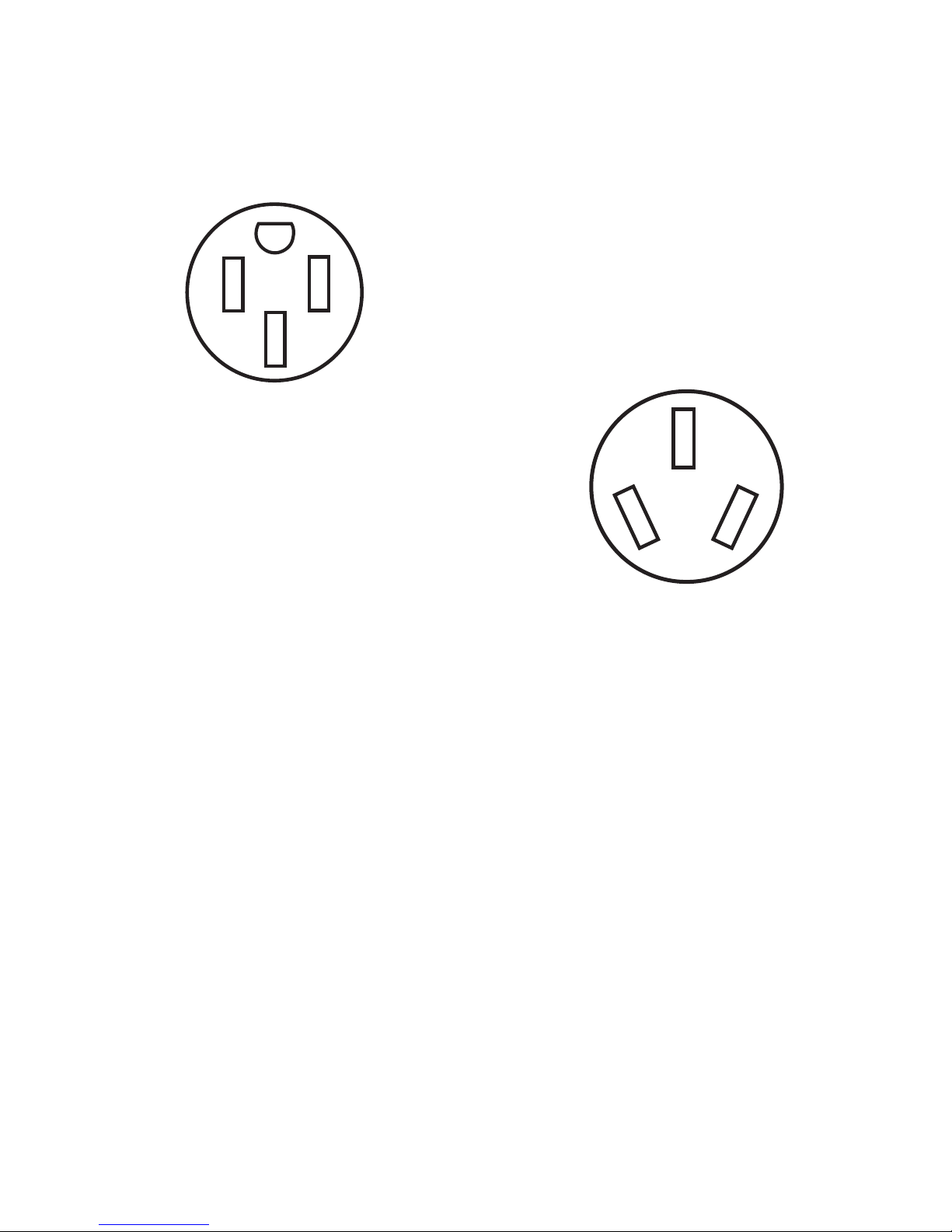
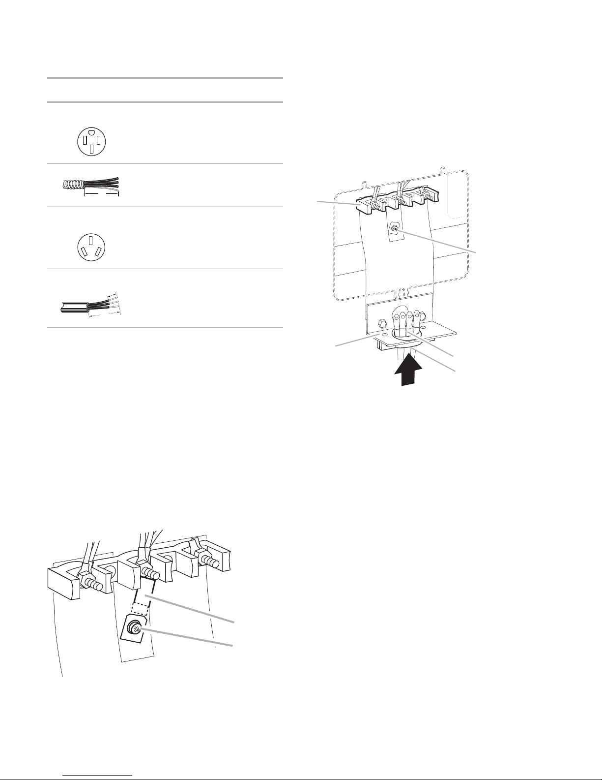
The cord should be Type SRD or SRDT with a
4-wire receptacle (14-50R)
3-wire receptacle (10-50R)
UL listed strain relief and be at least 4 ft (1.22
m) long.
The minimum conductor sized for the copper
4-wire power cord are:
If connecting to a 3-wire system:
Local codes may permit the use of a UL listed,
3-wire, 250 volt, 40-amp range power supply
cord (pigtail). This cord contains 3 copper conductors with ring terminals or open-end spade
terminals with upturned ends, terminating in a
NEMA Type 10-50P plug on the supply end.
Connectors on the appliance end must be provided at the point the power supply cord enters
the appliance. This uses a 3-wire receptacle of
NEMA Type 10-50R.
40-amp circuit
2 No.-8 conductors
1 No.-10 white neutral
1 No.-8 green grounding
2-5
INSTALLATION INSTRUCTIONS
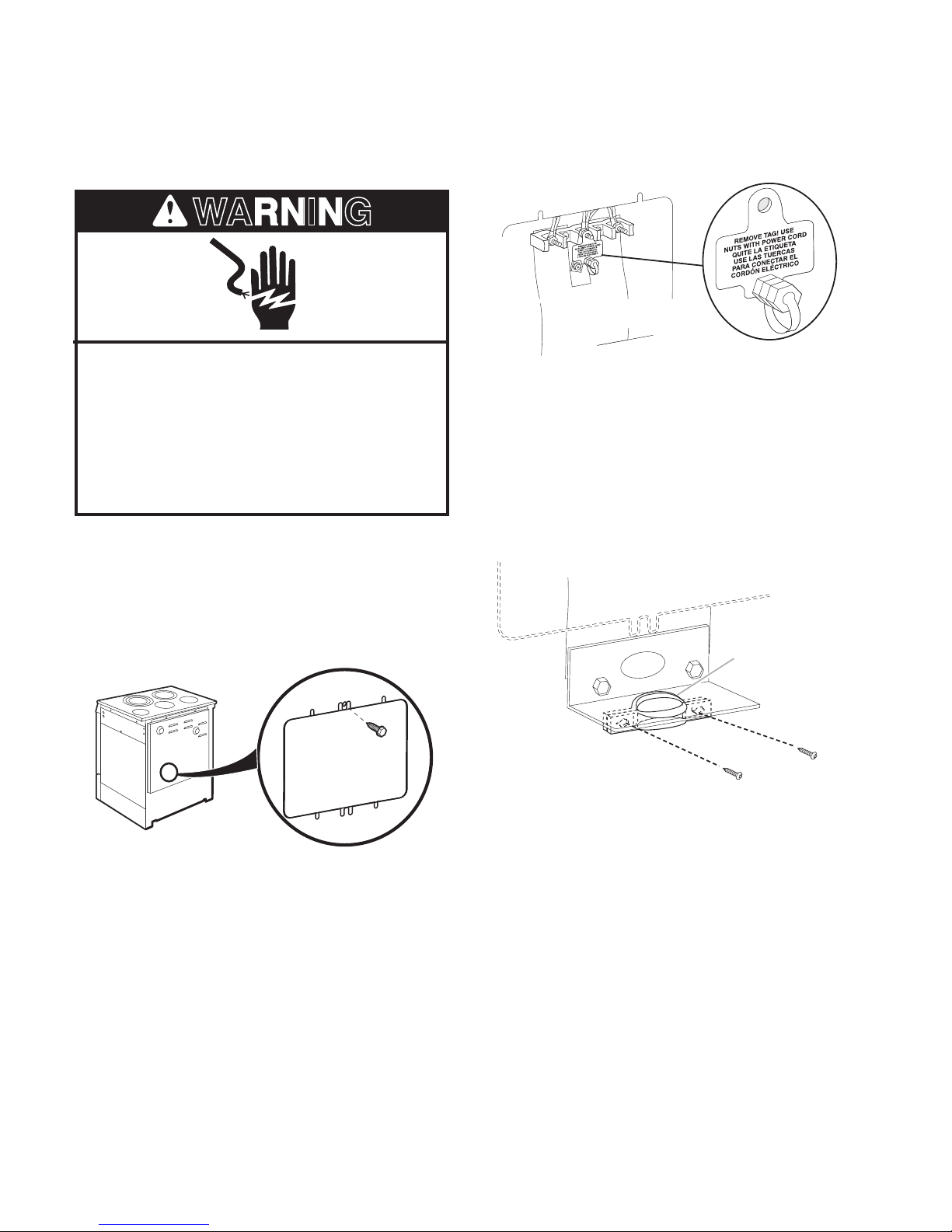
WARNING
A. UL listed strain relief
A
Electrical Connection
Power Supply Cord
Electrical Shock Hazard
Disconnect power before servicing.
Use a new 40 amp power supply cord.
Plug into a grounded outlet.
Failure to follow these instructions can
result in death, re, or electrical shock.
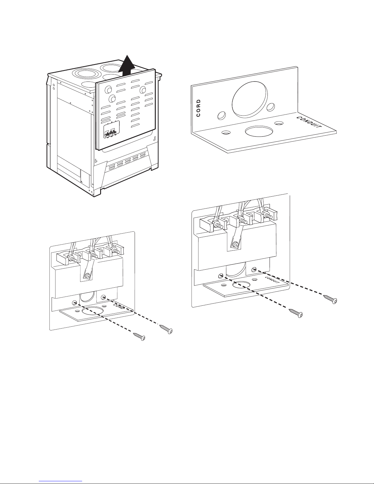
1. Disconnect power.
2. Use Phillips screwdriver to remove the
terminal block cover screw located on the
back of the range. Pull cover down and
toward you to remove cover.
4. Add strain relief.
Style 1: Power supply cord strain relief
Assemble a UL listed strain relief in the •
opening.
3. Remove plastic tag holding three 10-32
hex nuts from the middle post of the terminal block.
2-6
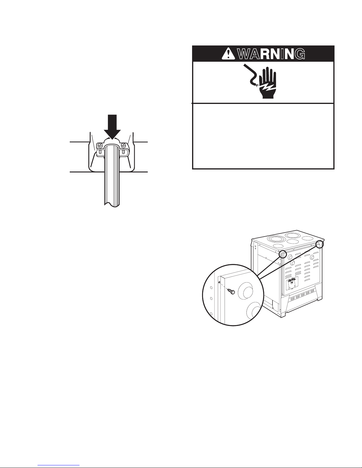
WARNING
Feed the power supply cord through the •
R
E
M
O
V
E
T
A
G
!
U
S
E
N
UTS
W
I
T
H
PO
W
E
R
C
O
R
D
Q
U
I
T
E
L
A
E
T
I
Q
U
E
T
A
U
S
E
LA
S
T
U
E
R
C
A
S
P
A
RA
C
O
NE
CT
A
R
E
L
C
O
R
D
Ó
N
EL
É
C
T
R
I
C
O
R
E
M
O
V
E
T
A
G
!
U
S
E
N
UTS
W
I
T
H
PO
W
E
R
C
O
R
D
Q
U
I
T
E
L
A
E
T
I
Q
U
E
T
A
P
A
RA
C
O
NE
CTA
R
E
L
C
O
R
D
Ó
N
EL
É
C
T
R
I
C
O
opening in the cord/conduit plate on bottom
of range. Allow enough slack to easily attach
the wiring to the terminal block.
Tighten strain relief screw against the power •
supply cord.
Direct Wire
Electrical Shock Hazard
Disconnect power before servicing.
Use 8 gauge copper wire.
Electrically ground cooktop.
Failure to follow these instructions can
result in death, re, or electrical shock.
Style 2: Direct wire strain relief
Use Phillips screwdriver to remove screws •
from panel on back of range.
2-7
Lift range back panel up and off.•
R
EM
O
V
E
T
A
G
!
U
S
E
N
U
T
S
W
I
T
H
P
O
W
E
R
C
O
R
D
Q
U
I
T
E
L
A
E
T
I
Q
U
E
TA
U
S
E
L
A
S
T
U
E
R
C
A
S
PA
R
A
C
O
NE
C
T
A
R
E
L
C
OR
D
Ó
N
E
L
É
C
T
R
I
C
O
R
EM
O
V
E
T
A
G
!
U
S
E
N
U
T
S
W
I
T
H
P
O
W
E
R
C
O
R
D
Q
U
I
T
E
L
A
E
T
I
Q
U
E
T
A
P
A
R
A
C
O
N
E
C
T
A
R
E
L
C
O
R
D
Ó
N
E
L
É
C
T
R
I
C
O
Use Phillips screwdriver to remove screws •
and slide cord/conduit plate down and out.
Position cord/conduit plate as shown in the •
following illustration.
Replace cord/conduit plate and insert •
screws.
2-8
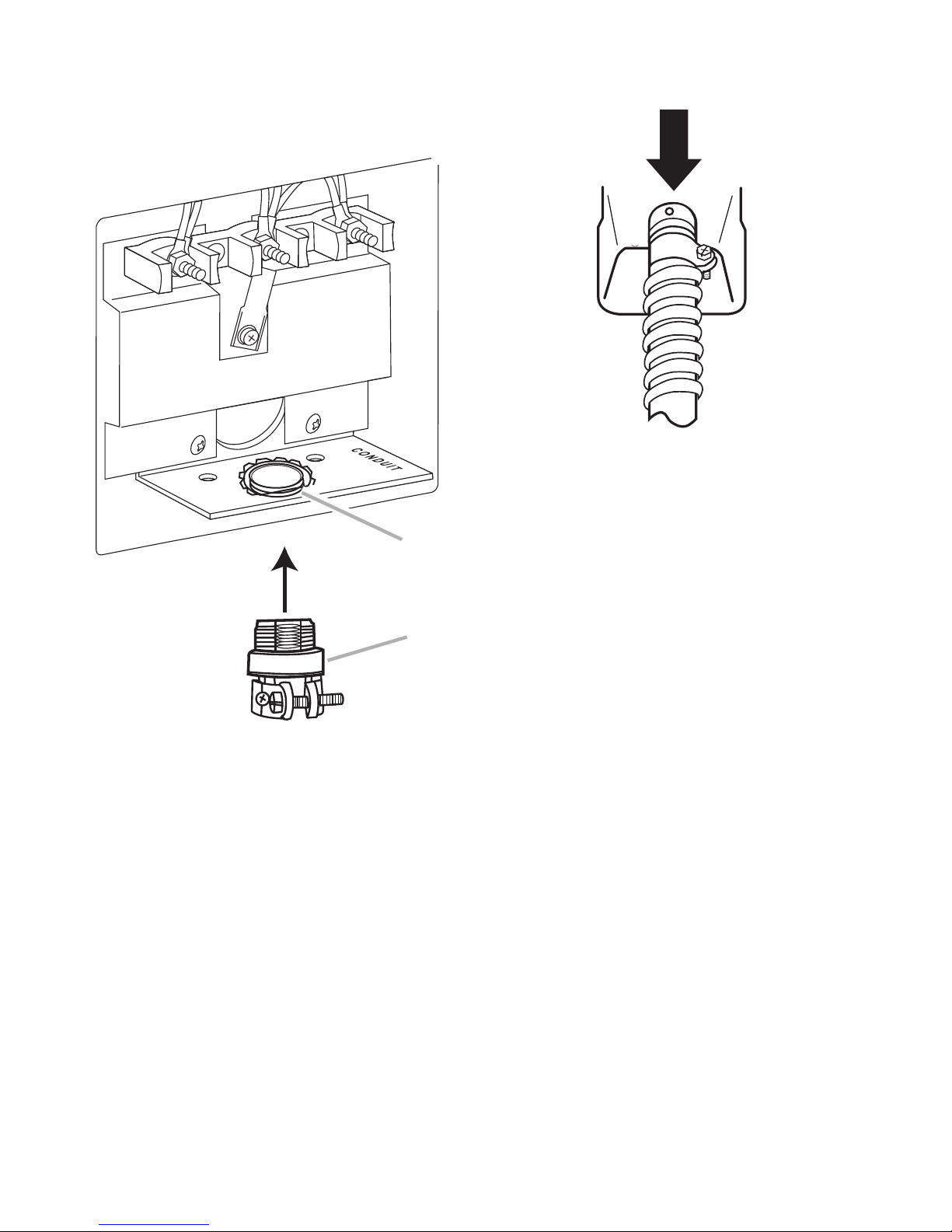
Assemble a UL listed conduit connector in •
A. Removable retaining nut
B. Strain relief
A
B
the opening.
5. Replace back panel and screws on rear of
range.
6. Complete installation following instructions
for your type of electrical connection:
Feedtheexibleconduitthroughthestrain•
relief, allowing enough slack to easily attach
wiring to the terminal block.
Tightenstrainreliefscrewagainsttheex-•
ible conduit.
4-wire (recommended)
3-wire (if 4-wire is not available)
2-9
Electrical Connection Options
If your home has: And you will be
connecting to:
Go to Section:
4-wire receptacle
(NEMA type 14-50R)
A UL listed,
250-volt
minimum,
40-amp, range
power supply
cord
4-wire connection:
Power supply cord
4-wire direct A fused
disconnect or
circuit breaker
box
4-wire connection:
Direct wire
3-wire receptacle
(NEMA type 10-50R)
A UL listed,
250-volt
minimum,
40-amp, range
power supply
cord
3-wire connection:
Power supply cord
3-wire direct A fused
disconnect or
circuit breaker
box
3-wire connection:
Direct wire
(12.7 cm)
5"
3"
(7.6 cm)
1"
(2.5 cm)
A. Metal ground strap
B. Ground-link screw
A
B
A. Terminal block
B. Ground-link screw
C. Cord/conduit plate
D. Power supply cord wires
E. Strain Relief
A
B
C
D
E
2. Use Phillips screwdriver to remove the
ground-link screw from the back of the
range. Save the ground-link screw.
3. Feed the power supply cord through the
opening in the cord/conduit plate on bottom of range. Allow enough slack to easily
attach the wiring to the terminal block.
4-wire connection: Power Supply Cord
Use this method for:
New branch-circuit installations (1996 •
NEC)
Mobile homes•
Recreational vehicles•
I n a n a r e a w h e r e l o c a l c o d e s p r o h i b i t g r o u n d -•
ing through the neutral
1. Part of metal ground strap must be cut out
and removed.
4. Use Phillips screwdriver to connect the
green ground wire from the power supply cord to the range with the ground-link
screw. The ground wire must be attached
rst.
2-10
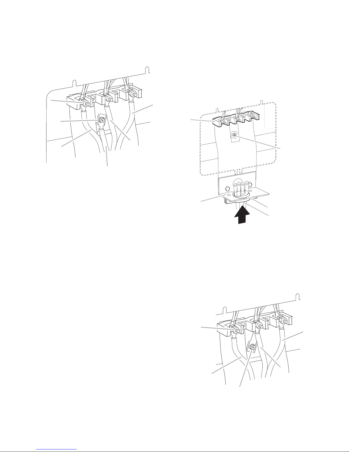
5. Use 3/8" nut driver to connect the neutral
A. 10–32 hex nut
B. Ground-link screw
C. Line 1 (black)
D. Green ground wire
E. Neutral (center) wire
F. Line 2 (red)
A
B
C
F
D
E
A. Terminal block
B. Ground-link screw
C. Cord/conduit plate
D. Power supply cord wires
E. Strain Relief
A
B
C
D
E
A. 10–32 hex nut
B. Line 1 (black)
C. Ground-link screw
D. Neutral (white) wire
E. Line 2 (red)
A
B
C
D
E
(white) wire to the center terminal block
post with one of the 10–32 hex nuts.
3-wire connection: Power Supply Cord
Use this method only if local codes permit connecting chassis ground conductor to neutral
wire of power supply cord.
1. Feed the power supply cord through the
opening in the cord/conduit plate on bottom of range. Allow enough slack to easily
attach the wiring to the terminal block.
6. Connect line 1 (black) and line 2 (red) wires
to the outer terminal block posts with 10-32
hex nuts.
7. Securely tighten hex nuts.
NOTE: For power supply cord replacement, only
use a power cord rated at 250 volts minimum,
40 amps or 50 amps that is marked for use
with nominal 3/8" (3.5 cm) diameter connection opening, with ring terminals and marked
2. Use 3/8" nut driver to connect the neutral
(white) wire to the center terminal block post
with one of the 10–32 hex nuts.
for use with ranges.
8. Replace terminal block access cover.
2-11
 Loading...