

Whirlpool RJH 3330-1 User Manual
READ AND SAVE THESE INSTRUCTIONS
YLrlmml
1 CORPORATION
INSTALLATION
AND
OPERATING
INSTRUCTIONS
FOR
MICROSHELF HOOD
MODEL RJH 3330-l
Before you begin,
completely and carefully. If followed, they will simplify
the installation job.
read the following instructions
NOTE: The fan in the Microshelf Hood turns on
automatically to protect the microwave oven
when the temperature inside the hoodreaches
122°F (SO’C). It turns off automatically when
the temperature falls below 95°F (35°C).
I. INSTALLATION REQUIREMENTS
A. Space Requirements
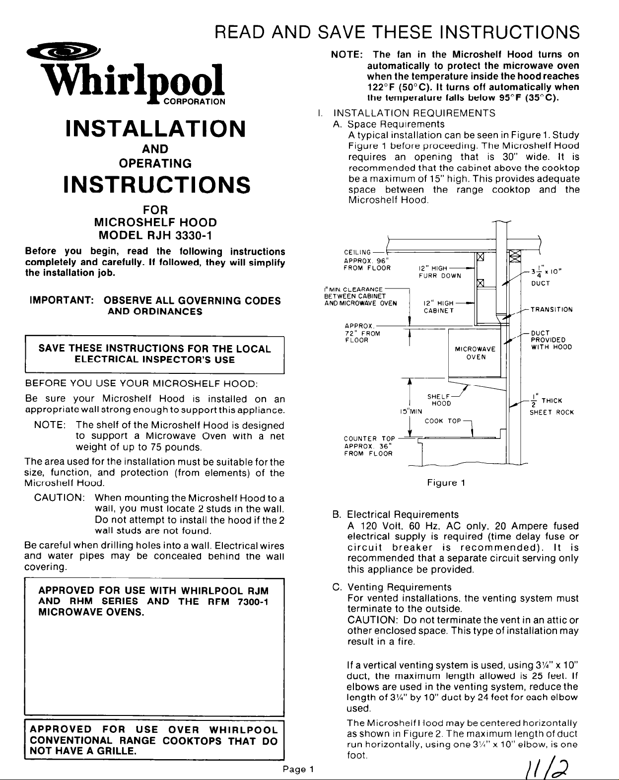
A typical installation can be seen in Figure 1. Study
Figure 1 before proceeding. The Microshelf Hood
requires an opening that is 30” wide. It is
recommended that the cabinet above the cooktop
be a maximum of 15” high. This provides adequate
space between the range cooktop and the
Microshelf Hood.
l-
CEILING --(
APPROX 96”
FROM FLOOR
FURR DOWN
%I
3;‘. IO”
F
1 DUCT
IMPORTANT: OBSERVE ALL GOVERNING CODES
AND ORDINANCES
SAVE THESE INSTRUCTIONS FOR THE LOCAL
ELECTRICAL INSPECTOR’S USE
BEFORE YOU USE YOUR MICROSHELF HOOD:
Be sure your Microshelf Hood is installed on an
appropriate wall strong enough tosupport this appliance.
NOTE: The shelf of the Microshelf Hood is designed
to support a Microwave Oven with a net
weight of up to 75 pounds.
The area used for the installation must be suitable forthe
size, function, and protection (from elements) of the
Microshelf Hood.
CAUTION: When mounting the Microshelf Hood to a
wall, you must locate 2 studs in the wall.
Do not attempt to install the hood if the 2
wall studs are not found.
Be careful when drilling holes into a wall. Electrical wires
and water pipes may be concealed behind the wall
covering.
APPROVED FOR USE WITH WHIRLPOOL RJM
AND RHM SERIES AND THE RFM 7300-l
MICROWAVE OVENS.
TRANSITION
%
DUCT
FLOOR
B. Electrical Requirements
A 120 Volt, 60 Hz, AC only, 20 Ampere fused
electrical supply is required (time delay fuse or
circuit breaker is recommended). It is
recommended that a separate circuit serving only
this appliance be provided.
C. Venting Requirements
For vented installations, the venting system must
terminate to the outside.
CAUTION: Do not terminate the vent in an attic or
other enclosed space. This type of installation may
result in a fire.
T
t u
I5”MIN
COOK TOP?
MICROWAVE
SHELF1
n000
Figure 1
OVEN
PROVIDED
WITH HOOD
II
$ THICK
SHEET ROCK
APPROVED FOR USE OVER WHIRLPOOL
CONVENTIONAL RANGE COOKTOPS THAT DO
NOT HAVE A GRILLE.
If a vertical venting system is used, using 3%” x 10”
duct, the maximum length allowed is 25 feet. If
elbows are used in the venting system, reduce the
length of 3%” by 10” duct by 24 feet for each elbow
used.
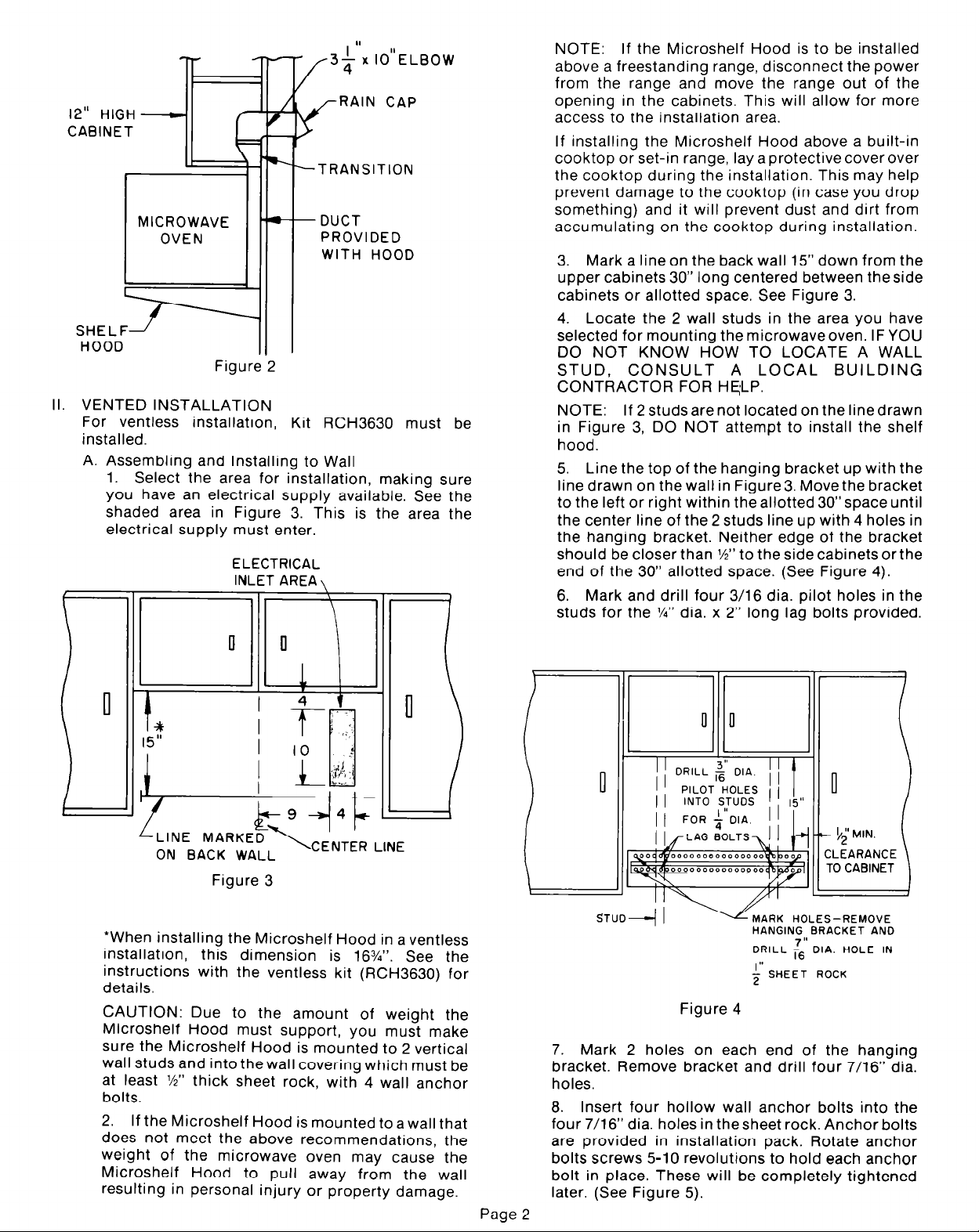
The Microshelf Hood may be centered horizontally
as shown in Figure 2. The maximum length of duct
run horizontally, using one 3%” x 10” elbow, is one
foot
Page 1
+“x IO”ELBOW
RAIN CAP
12” HIGH
CABINET
TRANSITION
DUCT
PROVIDED
WITH HOOD
SHELF/
HOOD
Figure 2
II. VENTED INSTALLATION
For ventless installation, Kit RCH3630 must be
installed.
A. Assembling and Installing to Wall
1. Select the area for installation, making sure
you have an electrical supply available. See the
shaded area in Figure 3. This is the area the
electrical supply must enter.
ELECTRICAL
INLET AREA \
NOTE:
If the Microshelf Hood is to be installed
above a freestanding range, disconnect the power
from the range and move the range out of the
opening in the cabinets. This will allow for more
access to the installation area.
If installing the Microshelf Hood above a built-in
cooktop or set-in range, lay a protective cover over
the cooktop during the installation. This may help
prevent damage to the cooktop (in case you drop
something) and it will prevent dust and dirt from
accumulating on the cooktop during installation.
3. Mark a line on the back wall 15” down from the
upper cabinets 30” long centered between theside
cabinets or allotted space. See Figure 3.
4. Locate the 2 wall studs in the area you have
selected for mounting the microwaveoven. IF YOU
DO NOT KNOW HOW TO LOCATE A WALL
STUD, CONSULT A LOCAL BUILDING
CONTRACTOR FOR HELP.
NOTE:
If 2 studs are not located on the line drawn
in Figure 3, DO NOT attempt to install the shelf
hood.
5. Line the top of the hanging bracket up with the
line drawn on the wall in Figure 3. Move the bracket
to the left or right within the allotted 30”space until
the center line of the 2 studs line up with 4 holes in
the hanging bracket. Neither edge of the bracket
should be closer than l/2” to the side cabinets or the
end of the 30” allotted space. (See Figure 4).
6. Mark and drill four 3/16 dia. pilot holes in the
studs for the l/4” dia. x 2” long lag bolts provided.
ON BACK WALL
Figure 3
*When installing the Microshelf Hood in a ventless
installation, this dimension is 16%“. See the
instructions with the ventless kit (RCH3630) for
details.
CAUTION: Due to the amount of weight the
Microshelf Hood must support, you must make
sure the Microshelf Hood is mounted to 2 vertical
wall studs and into the wall covering which must be
at least %” thick sheet rock, with 4 wall anchor
bolts.
2. If the Microshelf Hood is mounted to a wall that
does not meet the above recommendations, the
weight of the microwave oven may cause the
Microshelf Hood to pull away from the wall
resulting in personal injury or property damage.
Page 2
CLEARANCE
TO CABINET
STUD+ 1
-MARK HOLES-REMOVE
HANGING BRACKET AND
DRILL &’ DIA. HOLE IN
II
+ SHEET ROCK
Figure 4
7. Mark 2 holes on each end of the hanging
bracket. Remove bracket and drill four 7/16” dia.
holes.
8. Insert four hollow wall anchor bolts into the
four 7/16” dia. holes in thesheet rock. Anchor bolts
are provided in installation pack. Rotate anchor
bolts screws 5-10 revolutions to hold each anchor
bolt in place. These will be completely tightened
later. (See Figure 5).
 Loading...