

Whirlpool RGH 8300-2 User Manual
READ AND SAVE THESE INSTRUCTIONS .............
!KSTALLAT!ON and OPERATING [SnISIRUCTIONS •
for ‘
.
. .
Wi
VENTED RANGE HOOD rgh83oo-is
—r- TO INSTALL RANGE HOOD
This unit can be vented vertically through upper cabinets or
horizontally through an outside wall. A typical vertical installation is
shown in Figure 1. A typical horizontal installation is shown m Figure
2. For proper ventilation when used with an indoor electric grill, see
page 2 for guidelines for proper duct sizing. Improper duct sizing or
installation of restrictive roof jacks can reduce air moving capacity
and provide inadequate ventilation for an Indoor electric grill. For
most efficient smoke removal, the top of the hood should be
approximately 55 inches (137.6 cm) from the floor.
1. Make a template or transfer measurements shown in Fig. 3 to
cabinets or wall. ■
2. Cut holes to accomodate ventilating duct allowing ’i" ( 6 cm)
clearance on all 4 sides for back vent. Allow (1.9 cm) clearance
toward front for vertical vent. Allow Vi" (.6 cm) on others sides for top
vent.
3. Cut appropriate hole for electrical wiring.
4. Run wire through wall or cabinets according to National
Electrical Code and applicable local codes. (DO NOT turn power on
until installation is complete.)
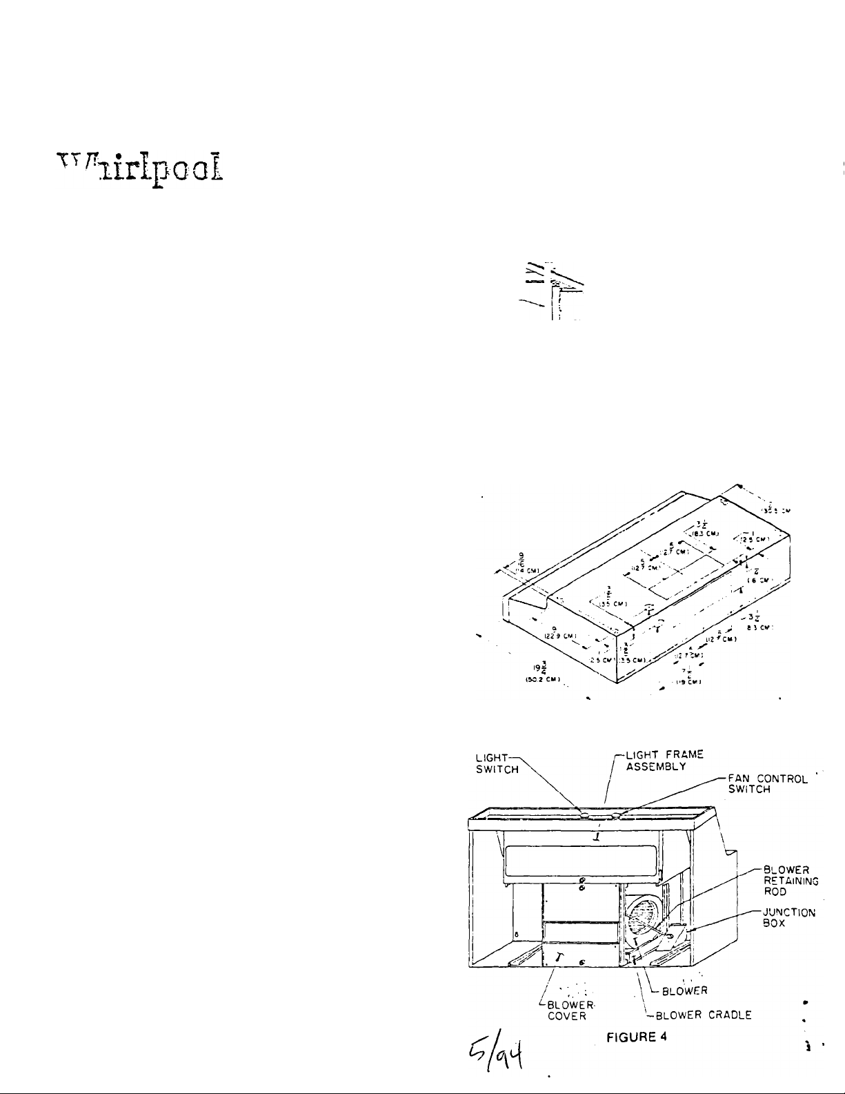
5. For an easier installation, remove the filters and the three
assemblies shown in Fig. 4. This reduces the weight about 40%. The
blov^er cover and light frame assembly are held into place with thumb
screv;s. To remove the blower assembly, first unplug the blower
power supply cord from the junction box. Remove the packing screw
from the blower retaining rod. then pull the blower retaining rod to
one side, freeing it from between the bumps on the blower housing.
6. Remove screw holding junction box cover.
7. Remove proper electrical knockout. See Figure 3.
8. Remove proper venting knockout. See Figure 3. NOTE: If
horizontal discharge is selecTed an additional knockout in the blower
cradle must be removed.
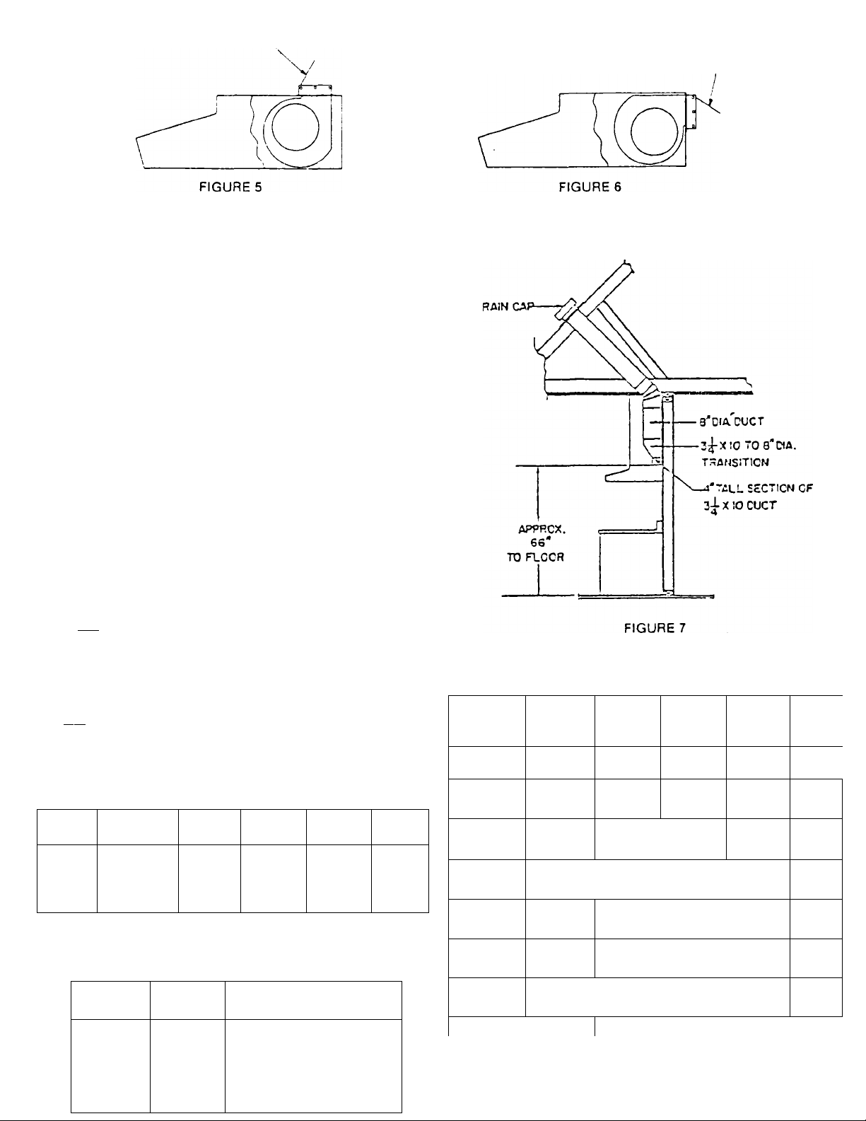
9. Attach the damoer as shov/n in Figure 5 for vertical discharge or
Fig. 6 for horizontal discharge.
10. Lift the hood into position. Mark location of four mounting holes.
11. Remove hood and start all four screws in center of narrow neck of
keyhole slot marked on cabinet bottom.
12. Lift the hood into position simultaneously feeding the electrical
wire through the knockout. Follow aoplicable local codes and/or
latest National Electrical Code for electrical connector to be used at
field wiring entrance.
13. Tighten screws to secure hood. Be sure screw head is in narrow
neck of keyhole slot.
14. Install proper duct work. See page 2.
15. Complete electrical wiring in junction box according to the
National Electrical Code and applicable Local Codes. NOTE: This
unit must be permanently grounded in accordance with the National
Electrical Code and applicable Local codes.
16. Replace junction box cover.
17. Replace blower. See page 3 for proper blower orientation
18. Replace blower cover, light frame assembly and filters. .
NOTE: It has been found that a large part of the energy loss of the
average home is due to outside air infiltrating the structure. Seal
around ductwork wnere it passes through outside walls or ceiling.
Seal around electrical wiring also. „
. /
- RSH83oo-as
----------------------------------------
I ■
FIGURE 1
FIGURE 3
t— WiPiNG »'NCt'Cw’
FIGURE 2
•
СДМРЕР) BLAOE
ТО FRONT
Guideline fo Proper Duct Sizing for Ventilating An Indoor Electric Grill
These Guidelines are to insure adequate ventilation for an indoor
Electric Grill. Indoor electric grills produce more smoke than
normal cooking and requires at least410CFM to provide adequate
ventilation. Less stringent ventilating requirements can deviate
from these recommendations.
HORIZONTAL VENTING;
Figure 2 on page 1 shows a direct discharge to the outside
through a wall rain cap. Due to the lov/erCFM rating in this venting
position, duct must De limited to a maximum of 2 feet of 3'/* x 10
inch duct capped v/ith a wall rain cap with a free discharge area of
at least 66 inches square. There should be no bends in the
connecting duct between the hood and the wall rain cap.
VERTICAL VENTING:
Figure 1 on page 1 shows an installation using 3 feet of 3% x 10
inch duct terminating in a roof rain cap. In table 1 we see that 3 feet
of 3'.i X 10 inch duct is the maximum length of 3>4 x 10 inch duct
recommended.
Figure 7 shews an installation requiring more duct length. A
transition to round is used as close to the hood as possible to
eliminate the restriction caused by the 3'i x 10 duct. 45:1 bends
should be used instead of 90^ bends wherever possible.
For example, ifthestraightlengthsofductinFig.7 total 9 ft. the
elbow IS 45^ and the roof ram cap has 113 in' free area, choose the
duct size required. The 45’' elbow can be approximated by dividing
the equivalent duct lengths in Table 2 by two.
Since we already have 9 ft. of straight duct, Table 1 tells us that 7"
dia. IS too small. So we try 8" dia.
9 ft. Straight Duct ‘
6 ft. Equivalent straight length of 45° elbow (8" Dia.)
15 ft.
Fifteen feet is over the maximum of 13 ft. for 8" dia. duct, so 8"
duct IS to small.
Move to 9" dia. duct and run through the calculations again.
9 ft. Straight Duct.
7 ft. Equivalent straight length of 9" dia. duct for 45° elbow
16 ft.
Sixteen feet is under the maximum of 25 ft. for 9" dia. duct, so 9"
duct IS a good choice.
table I
Vertical Venting
Duct
Size
3'4 X 10" 7" d.ia.
8" dia. 9" dia.
10" dia.
Max
Duct
Length
(Feet)
3
7 .
13
25 40
Table 1 shows the maximum length of duct to be used in
conjunction witn a roof ram cap having a free area of 113 m'.
TABLE 2
Duct
Size
Equivalent length of
straight duct of same dia.
7" dia. 11 ft.
—
90°
Elbow
8" dia. 12 ft.
9" dia.
10" dia.
14 ft.
16 ft.
DAMPER BLADE
TO TOP
CFM vs. DUCT LENGTH FOR RGH SERIES HOOD
Equivalent Duct Length (ft.)
Static
Pressure
.06
.10
.15
.20
.25
.275
CFM
460
440
417
355
330
3-% X 10
Reel.
4
7
12 j 25.0
! i i
390 18 1 40 ! 77
i 1 1
26 I 61 1 104
7" dia.
8.5 17
16.0
1 1
34 1 73 j ■' 145
8" dia.
31
50
9" dia.
30
55.5
88
142
1 ' '
.30
TR ! 1ЙП izn ! ! !
250 1 65 I ■ 136 !
1 ' !
NOTE; The above table is based on- vemc-al disc iTLe. The values
m this table are for duct length only and со not account tor static
□ rassure loss throuoh roof mounted ram c. ps.
 Loading...