

Whirlpool RF388LXKT0, RF388LXKP0, RF388LXKQ0, RF388LXKB0, GR458LXLT0 Installation Guide
...Page 1

Quick Reference
Before you start
Product dimensions
Cabinet dimensions/requirements
Electrical requirements
Installation steps
If range does not operate
If you need assistance/service
Moving the range
if you need assistance:
Check your Use and Care Guide for a toll-free number to call or call the
dealer from whom you purchased this appliance. The dealer is listed in
the Yellow Pages of your phone directory under "Appliances --
Household -- Major -- Service and Repair."
Call when you:
[] Have questions about range installation or operation.
[] Need to obtain the name and number of an authorized
service company.
When you call, you will need:
[] The range model number.
[] The range serial number.
Both numbers are listed on the model/serial rating plate located on the
oven frame behind the storage drawer )anel.
Page 2

Your safety and the safety of
others are very important.
We have provided many important safety
messages in this manual and on your
appliance. Always read and obey all safety
messages.
This is the safety alert symbol.
This symbol alerts you to potential
hazards that can kill or hurt you and others.
All safety messages will be preceded by the
safety alert symbol and the word "DANGER"
or "WARNING". These words mean:
You can be killed or seriously injured if
you don't immediately follow
instructions.
You can be killed or seriously injured if
you don't follow instructions.
All safety messages will tell you what the
potential hazard is, tell you how to reduce
the chance of injury, and tell you what can
happen if the instructions are not followed.
27-1/8" depth
with handle
46-7/8"
overall
height
24-13/16"
Important: Observe all governingcodes and
ordinances.Failure to meet codes and ordinances
could lead to fire orelectrical shock.
Proper installation is your responsibility. A qualified
technician must install this range. Make sure you
have everything necessary for correct installation. It
is the installer's responsibility to comply with
installation clearances specified on the model/serial
rating plate. The model/serial rating plate is located
on the oven frame behind the storage drawer panel.
Check location where range will be installed. The
range should be located for convenient use in
kitchen.
When installing a range under existing cabinets and
the installation does not meet the minimum cabinet
clearances, install a range hood above the cooktop
to avoid burn hazards.
ALL OPENINGS IN THEWALL OR FLOORWHERE
RANGE IS TO BE INSTALLED MUST BE SEALED.
Cabinet opening dimensionsthat are shown must
be used. Given dimensions are minimum
clearances.
Grounded electrical outlet is required. See
"Electrical requirements," Page 3.
opening width
I .,_1 _/°penmg w_n _ clearance to the top
, r'_ _ " of the cooktop, see
18" rain,
clearance upper
cabinet to
countertop 1
_ width
countertop
space to side
wall or other
4" rain.
combustible
material
30-1/8" opening
Wall receptacle --
8" to 22" from either
cabinet, 5-1/2" max.
5-1/2" receptacle as shown.
max. /
from floor. Position
Note.**
Do Not pinch the power
supply cord between the
range and the wall.
Do Not seal the range to
the side cabinets.
Mobile home installation
The installation of this range must conform with the
Manufactured Home Construction and Safety
Standard, Title 24CFR, Part 3280 [formerly the
Federal Standard for Mobile Home Construction
and Safety, Title 24, HUD (Part 280)] or, when such
standard is not applicable, the Standard for
Manufactured Home Installations,ANSI/NCSBCS
A225.1 and Manufactured Home Installations,Sites
and Communities ANSl/NFPA 501A_,or with local
codes.
When this range is installed in a mobile home, it
must be secured to the floor during transit. Any
method of securing the range is adequate as long
as it conforms to the standards listed above.
Four-wire power supply cord or cable must be used
in a mobile home installation. The appliance wiring
will need to be revised. See "Four-wire electrical
connection," Page 4.
Copies of the standards listed may be obtained from:
* National FireProtection Association
Batterymarch Park
Quincy,Massachusetts02269
Anti-tip bracket
The floor-mounted anti=tip
bracket MUST be installed.
To install the anti-tip
bracket shipped with the
range, see Page 3 and the
anti-tip bracket template/
instruction sheet.
_Note: 24" rain, when bottom of wood or metal
cabinet is protected by not less than 1/4" flame
retardant millboard covered with not less than
No, 28 MSG sheet steel, 0.015" stainless steel,
0.024" aluminum or 0.020" copper.
30" rain, clearance between the top of the
cooking platform and the bottom of an
unprotected wood or metal cabinet.
F \\\
Page 2
level
screwdriver
or ruler
measuring tape
3/8" drive
3/8" and 5/16"
nut driver
_%% wood floors:
"_ 1/8" drill bit
safety
glasses
concrete/ceramic floors:
3/16" carbide-tipped masonry
drill bit (Hammer may be
needed for anchors.)
channel lock
2 plastic
%ors
_)_2 screws (#10 × 1-1/2")
floor-mounted
anti-tip bracket Not shown:
literature pack
Brackets must be securely mounted to sub-floor. Thickness of
flooring may require longer screws to anchor bracket to sub-
floor. Longer screws are available from your local hardware
store.
Page 3
Electrical Shock Hazard
Electrically ground range.
Failure to follow this instruction could result in
death, fire or electrical shock.
if codespermit and a separate ground wire is used,
it isrecommended that a qualified electrician
determine that the ground path and wire gauge are
in accordancewith local codes.
Do Not ground to a gaspipe.
Checkwith a qualified electrician if you are not
sure range is properly grounded.
Do Not have a fuse in the neutral or ground circuit.
Recommended ground method
It is the personal responsibility and obligation of the
customer to contact a qualified electrician to assure
that the electrical installation is adequate and is in
conformance with the National Electrical Code,
ANSI/NFPA 70- latest edition _ and all local codes
and ordinances.
Copies of the standards listed above may be
obtained from:
* National Fire Protection Association
Batterymarch Park
Quincy, Massachusetts 02269
Power supply cord is not supplied, but is available
through your local electrical supply house.
Range must be connected to the proper electrical
voltage and frequency as specified on the
model/serial rating plate. (The model/serial rating
plate is located on the oven frame behind the
storage drawer panel.)
[] CONNECTION AT CONNECTION BLOCK MUST
BE COPPERWIRE ONLY.
If the house has aluminum wiring, follow the
procedure below:
a.) Connect a section of 8-gauge, solid copper
wire to the connector block.
b.) Connect the aluminum wiring to the added
section of copper wire using special
connectors designed and Underwriters
Laboratories-listed for joining copper to
aluminum. Follow the electrical connector
manufacturer's recommended procedure.
c.) Aluminum/copper connection must conform
with local codes and industry-accepted wiring
practice.
[] Athree-wire or four-wire, single-phase, 120/240-
volt, 60-Hz,AC-only, electrical supply (or three-wire
or four-wire 120/208-volt if specified on the
model/serial rating plate) is required on aseparate,
40-ampere circuit, fused on both sides of the line.
[] A time-delay fuse or circuit breaker is
recommended.
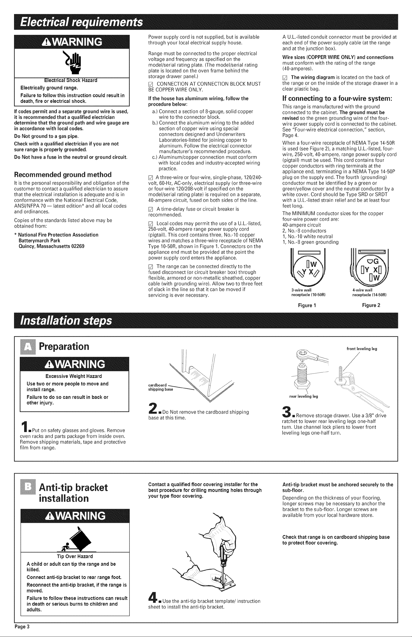
[] Localcodes may permit the use of a U.L.-listed,
250-volt, 40-ampere range power supply cord
(pigtail). This cord contains three, No.-10 copper
wires and matches a three-wire receptacle of NEMA
Type 10-50R,shown in Figure 1. Connectors on the
appliance end must be provided at the point the
power supply cord enters the appliance.
[] The range can be connected directly to the
fused disconnect (or circuit breaker box) through
flexible, armored or non-metallic sheathed, copper
cable (with grounding wire). Allow two to three feet
of slack in the line so that it can be moved if
servicing is ever necessary.
A U.L.-listed conduit connector must be provided at
each end of the power supply cable (atthe range
and at the junction box).
Wire sizes (COPPERWIREONLY) and connections
must conform with the rating of the range
(40-amperes).
[] The wiring diagram is located on the back of
the range or on the inside of the storage drawer in a
clear plastic bag.
If connecting to a four-wire system:
This range is manufactured with the ground
connected to the cabinet. The ground must be
revised so the green grounding wire of the four-
wire power supply cord is connected to the cabinet.
See "Four-wire electrical connection," section,
Page 4.
When a four-wire receptacle of NEMA Type 14-50R
is used (see Figure 2), a matching U.L.-listed, four-
wire, 250-volt, 40-ampere, range power supply cord
(pigtail) must be used. This cord contains four
copper conductors with ring terminals at the
appliance end, terminating in a NEMA Type 14-50P
plug on the supply end. The fourth (grounding)
conductor must be identified by a green or
green/yellow cover and the neutral conductor by a
white cover. Cord should be Type SRDor SRDT
with a U.L.-listed strain relief and be at least four
feet long.
The MINIMUM conductor sizes for the copper
four-wire power cord are:
40-ampere circuit
2, No.-8 conductors
1,No.d0 white neutral
1,No.-8 green grounding
3-wire wall 4-wire wall
receptacle (10-50R) receptacle (14-50R)
Preparation
ExcessiveWeight Hazard
Use two or more people to move and
install range.
Failure to do so can result in back or
other injury.
==Put on safety glasses and gloves. Remove
oven racks and parts package from inside oven.
Remove shipping materials, tape and protective
film from range.
cardboard
shipping base
=,Do Not remove the cardboard shipping
base at this time.
Figure 1 Figure 2
front leveling leg
/
\
rear leveling leg
=,Remove storage drawer. Use a 3/8" drive
ratchet to lower rear leveling legs one-half
turn. Use channel lock pliers to lower front
leveling legs one-half turn.
Anti-tip bracket
installation
Tip Over Hazard
A child or adult can tip the range and be
killed.
Connect anti-tip bracket to rear range foot.
Reconnect the anti-tip bracket, if the range is
moved.
Failure to follow these instructions can result
in death or serious burns to children and
adults.
Page3
Contact a qualified floor covering installerfor the
best procedure for drilling mounting holes through
your type floorcovering.
,, Use the anti-tip bracket template/instruction
sheet to install the anti-tip bracket.
Anti-tip bracket must be anchored securely to the
sub-floor.
Depending on the thickness of your flooring,
longer screws may be necessary to anchor the
bracket to the sub-floor. Longer screws are
available from your local hardware store.
Check that range is on cardboard shipping base
to protect floor covering.
Page 4

Electricalconnection
GROUNDING iNSTRUCTiONS: This range must
be grounded, inthe event of malfunction or
breakdown, groundingwill reduce the risk of
electricshock by providing a path of least
resistance for electric current.
if using a power supply cord, the plug must be
plugged into an appropriate outlet that is
properly installed and grounded in accordance
with all localcodes and ordinances.
if using a direct wire connection, this range must
be connected to a grounded metal, permanent
wiring system; or anequipment-ground
conductor must be run with the circuit
conductorsand connected to the equipment-
ground terminal or lead on the range.
Pull coverdown and
terminal
block cover
3/8"
brassnuts
located inside
cover
he×-head
screws
==Removethe terminal block cover screws
located on the backof range. Pull cover down and
towards you to remove cover from range.
Electrical Shock Hazard
Turn power supply off before connecting cord.
Use a new 40-ampere power supply cord.
Plug into a grounded outlet.
Failure to follow these instructions can result
in death, fire, or electricalshock.
WARNING - Improper connection of the equipment-
grounding conductor can result in a risk of electric
shock. Check with a qualified electrician or
serviceman if you are in doubt as to whether the
appliance is properly grounded. Do not modify the
power supply cord plug. If it will not fit the outlet,
have a proper outlet installed by a qualified
electrician.
This range is manufactured with the neutral
terminal connected to the cabinet. Use a three-wire,
U.L.-listed, 40-ampere power supply cord (pigtail);
or if local codes Do Not permit ground through the
neutral, use a four-wire power supply cord rated at
250 volts, 40-amperes and investigated for use with
ranges. (See "Four-wire electrical connection.")
remove knockout ing for
for 40-ampere .. conduit
power cord and _ _-_ _ connector
U.L listed strain ____;_:_
rehef
o
©
1.Disconnectthe power supply.
2. Remove the knockout for the 40-ampere power
supply cord.
3. Assemble a U.L.-listed strain relief in the opening.
4. Insertthe power supply cord through the strain
relief, allowing enough slack to easily attach the
wiring to the terminal block.
5. Use only ring-type terminals to connect the
power supply. To secure the power supply cord,
usethe 3/8" brass terminal nuts attached to the
inside of the terminal block cover. Besure nuts
are installed tight.
6. Complete electrical connection according to your
type electrical supply ("Three-wire electrical
connection" or "Four-wire electrical connection.")
mDepending on your electrical supply, make
the three-wire or four-wire connection following
the "Power supply cord method" or "Direct wire
method" instructions.
Four-wire electrical connection:
round-link
ground
link
Figure 4
ground-link
screw
silver-colored
ground screw
neutral wire
(center wire)
line
Figure5
Usethis method for mobile homes and whenever
four-wire installation is required.
7. Remove the ground-link screw from the
range frame. Save the ground-link screw.
Bend up the ground link so that it does not
contact the range. See Figure 4.
8. Connect the green ground wire from power
supply cord to the range using the ground-
link screw. The groundwire must be
attached first and must not contact any other
terminal. See Figure 5.
9. Connect the neutral wire (center wire) to the
center, silver-colored terminal screw on the
terminal block using the brassterminal nuts
that are attached to the inside of the terminal
block cover. See Figure 5.
10.Connect the other two wires to the outer
terminals on the terminal block. See Figure 5.
11.Do Not loosen the factory-installed nuts
already on the terminal. Tighten nuts with 3/8"
nut driver for proper electrical connection.
12.Tighten the strain relief screws.
13. Replace the terminal block cover.
14. Plug power supply cord into grounded
electrical outlet.
terminal
teen
ground wire
line 2
U.L listed strain
relief and 40-ampere
range power supply
cord
Three-wire electrical connection:
silver-colored
terminal
block screw
line 1
U,L-listed strain relief
and 40-ampere range
power supply cord
Figure 3
Usethis method ONLY if local codesPERMIT
connecting cabinet-ground conductor to neutral
wire of power supply cord.
7. Use the brass terminal nuts attached to the
inside of the terminal block cover to connect
the neutral wire (center wire) to the silver-
colored terminal screw on the terminal block.
See Figure 3.
8. Connect the other two wires to outer
terminal screws on the terminal block. See
Figure 3.
9. Do Not loosen factory-installed nuts already
on the terminal. Tighten nuts with 3/8" nut
driver for proper electrical connection.
10.Tighten the strain relief screws.
11. Replace the terminal block cover.
12. Plug power supply cord into grounded
electrical outlet.
link
(center wire}
Page 4
Page 5

Electrical Shock Hazard
Turn power supply off before connecting
wires.
Use8-gauge solid copper wire.
Electricallyground range.
Failureto follow these instructions can result
in death, fire, or electrical shock.
.
Form the bare wire into a II u
"U'-shaped hook.
6.
Insert the power supply cable
through the conduit connector,
allowing enough slack to easily
attach the
wiring terminal block.
.
Complete electrical connection according to
your type electrical supply ("Three-wire
electrical connection" or "Four-wire
electrical connection.")
Four-wire electrical connection:
10. Connect the neutral wire (white wire) to the
center, silver-colored terminal screw on the
terminal block using the brass terminal
nuts that are attached to the inside of the
terminal block cover. See Figure 8.
11. Connect the other two wires to the outer
terminals on the terminal block.
See Figure 8.
12. Do NOT loosen the factory-installed nuts
already on the terminal. Tighten nuts with
3/8" nut driver for proper electrical
connection.
13. Tighten the locking ring and clamping
screws of the conduit connector.
14. Replace the terminal block cover.
Three-wire electrical connection:
This range may be connected directly to the fuse
disconnect or circuit breaker box; or with a U,L-
listed, 40-ampere range power supply cable.
Depending onyour electrical supply, make the
requiredthree-wire or four-wire connection,
U.L-listed conduit
connector.
1.Disconnectthe power supply.
2. Remove the knockout for the power supply
cable.
3. Assemble a U.L.-listed conduit connector in
the power supply cable opening.
4. Strip outer covering back 3 inches from end,
exposing wires. Strip the insulation back
1 inch from the end of each wire.
link _ screw
Figure7
,si,lver-colored
screw
from power
supply cable
block
neutral wire
(white wire)
conduit
connector and
power supply
cable
Figure 8
Use this method for mobile homes and
whenever four-wire installation is required,
8. Remove the ground-link screw from the
range frame. Save the ground-link
screw. Bend up the ground link so that it
does not contact the range. See Figure 7.
9. Connect the bare ground wire from
power supply cable to the range using the
ground-link screw. The ground wire
must be attached first and must not
contact any other terminal, See Figure 8.
0roo°d
_ SCreW
link
line1"_ _A
Figure 6
Use this method ONLY if localcodesPERMIT
connecting cabinet-ground conductor to
neutral wire of power supply came.
8. Use the brass terminal nuts attached to the
inside of the terminal block cover to
connect the neutral wire (white wire) to the
silver-colored terminal screw on the
terminal block. See Figure 6.
9. Connect the other two wires to outer
terminal screws on the terminal block.
See Figure 6.
10. Do Not loosen factory-installed nuts
already on the terminal Tighten nuts
with 3/8" nut driver for proper electrical
connection.
11.Tighten the locking ring and clamping
screws of the conduit connector.
12. Replace the terminal block cover.
ine 2
connector and power
supply cable.
Operating position
Before moving range across floor, check that
range is still on cardboardshipping base to
protect floor covering,
anti-tip _
bracket_
==Making sure the anti-tip bracket is
installed:
• Look for the anti-tip bracket securely attached
to floor.
• Slide range back so rear range foot is under
anti-tip bracket.
[] If installing the range in a mobile home,
you MUST secure the range to the floor. Any
method of securing the range is adequate as
long as it conforms to the standards in the
"Mobile home installation" instructions, Page 2.
[] Place rack in oven. Place
level on rack, first side to side; then front to back.
If range is not level, pull range forward until rear
leveling leg is removed from the anti-tip bracket.
Use 3/8" drive ratchet and channel lock pliers to
adjust leveling legs up or down until range is
level. Push range back into position. Check that
rear leveling leg is engaged in anti-tip bracket.
Note: Oven must be level for satisfactory baking
conditions,
[] Replace the storage drawer or lower
panel.
Check operation
O O FRONT OFF
®o
LO HI
2 8
3 7
/
4/5\_
elements: Push in and turn each surface unit
control knob to "HI" position. Check the operation
of the cooktop elements and indicator lights.
broil elements: Follow the instructions for your
type oven controls.
1.Set the oven temperature control to 350°F.
2. Set the oven temperature control to "BROIL."
3. Turn the control knob to the "OFF" position.
[] Check the operation of the cooktop
[] Check the operation of the oven and
OFF PUSH TO
TURN
_TURNOFFOVENWHENFLASHING)
DOOR LOCKED/CLEANING Q
OVEN ON •
OVEN HEATING •
_CLOSEDOORWHENFLASHING)
450 400
•The bottom element should glow red and the
"OVEN ON" and "OVEN HEATING" indicator
lights should be on.
•The upper element should become hot but
not glow red. The "OVEN HEATING" indicator
light goes off when the oven is preheated.
•The upper element should glow red and the
"OVEN ON" and "OVEN HEATING'indicator
lights should be on.
OFF
e
® _ ® BAKE
BROIL
OFF
e
BROIL ®
500 ®
450 =
400 e / ® \
3;0 I 300
®150
°200
=250
1.Set the oven selector control to "BAKE" and
the oven temperature control to 350°.
•The bottom element should glow red and the
indicator light should be on.
•The upper element should become hot but
not glow red. The oven indicator light goes
off when the oven is preheated.
2. Set the oven selector to "BROIL" and the oven
temperature control to "BROIL".
•The upper element should glow red and the
indicator light should be on.
3.Turn the control knob to the "OFF" position.
Page 5
Page 6

1.Pressthe"BAKE"pad.
•The"BAKE"indicatorwilllight.
•"350"willappearinthedisplay.
•The"START7"indicatorwillbegin
toflashafter5seconds.
2.PresstheSTART/ENTERpad.
•The"HEAT"and"ON"indicatorswilllight.
•Thedisplaywillshowtheautomaticcountdown
time(6minutes)neededtopreheattheovenfor
selectedtemperature.
•Thebottomelementshouldglowred.
•Theupperelementshouldbecomehot,butnot
glowred.
Theovenispreheatedwhenthe"HEAT"indicator
lightgoesoff,youheara1-secondtoneandthe
countdownchangesto"350".
* Note:BAKEPREHEATmodewillnotbecome
activeifoventemperatureisover170°F;instead,
theBAKEmodeimmediatelybecomesactive.
3.Pressthe"OFF/CANCEL"pad.
4.Pressthe"CUSTOMBROIL"pad.
•"500"willappearinthedisplay.
•The"BROIL"indicatorwilllight.
•The"START7"indicatorwillbegintoflashafter
5seconds.
5.Pressthe"START/ENTER"pad.
•The"ON"and"HEAT"indicatorswilllight.
•Theupperelementshouldglowred.
6.Pressthe"OFF/CANCEL"pad.
BAKE -- @
BROIL--O
START ? _ I
HEAT --O •
CLEAN -- I/
DOOR LOCKED
rBAKECUSTOMAOTO1
L ,.o,CL%@
TIMER
BAKE -- • /
BROIL mO ®
START ? -- •
sL%AT--%7
DOOR LOCKED
ON
BROLCLEA
COOK TIME/
TIMED
BAKE -- @ /
BROIL--@ •
H EAT ="""=0
CLEAN -- •
DOOR --0
LOCKED
START TIME/ TIMER
DELAY
BAKE CUSTOMAUTO
ON
ON
SELF CLEANING OVEN
SELF CLEANING OVEN
SELF CLEANING OVEN
@ rSTART 0FF1
/ ENTER I CANCELI
1.Press the "BAKE" pad.
•The "BAKE" indicator will light.
• "3500F" will appear in the display.
2. Press the START/ENTER pad.
• "PrE" and "4:15" will appear in the display.
• "HEAT" and "ON" and indicators will light.
•The bottom element should glow red.
•The upper element should become hot but not
glow red.
The oven is preheated when the time in the display
counts down to "0:00," you hear a 1-second tone,
and "PrE" changes to "3500F."
3. Press the "OFF/CANCEL" pad.
4. Press the "CUSTOM BROIL" pad.
• "500OF"will appear in the display.
• "BROIL" indicator will light.
1.Press the "BAKE" pad.
The "BAKE" indicator will light.
"3500F" will appear in the display.
•The "START 7" indicator will light after 5
seconds.
2. Press the START/ENTER pad.
• "PrE" and the preheat countdown time will
appear in the display.
• "HEAT" and "ON" and indicators will light.
•The bottom element should glow red.
•The upper element should become hot but not
glow red.
5. Press the "START/ENTER" pad.
"HEAT" and "ON" indicators will light.
The upper element should glow red.
6. Press the "OFF/CANCEL" pad.
SELF-CLEANING OVEN
AUTOCLEAN
V V B....
CANCEL
The oven is preheated when the time in the display
counts down to "0:00," you hear a 1-second tone,
and "PrE" changes to "3500F."
3. Press the "OFF/CANCEL" pad.
4. Press the "CUSTOM BROIL" pad.
• "500OF"will appear in the display.
• "BROIL" indicator will light.
•The "START 7" indicator will light after 5
seconds.
5. Press the "START/ENTER" pad.
"HEAT" and "ON" indicators will light.
The upper element should glow red.
6. Press the "OFF/CANCEL" pad.
Page6
_ [STT[_flRT STMOEPI I _HR MiNv_ } START OFF
SELF-CLEANING OVEN
To get the most efficient use from your new electric range, read
your Use and Care Guide. Keep Installation Instructions and Guide
close to the electric range for easy reference.
AUTO
CLEAN
D 5SEC
AUTOCLEAN
V V B....
CANCEL
CANCEL
Page 7

if range does not operate:
[] Checkthat the circuit breaker is not tripped or
the house fuse blown.
[] Checkthat the power supply cord is plugged
into the wall receptacle.
[] See Use and Care Guide for troubleshooting
list.
If you need assistance:
Ifyou have questions about operating, cleaning or
maintaining your range:
[] Refer to Use and Care Guide.
[] Call the Consumer Assistance Center. Check
your Use and Care Guide for a toll-free number
to call or call the dealer from whom you
purchased this appliance. The dealer is listed in
the Yellow Pagesof your phone directory under
"Appliances -- Household --Major -- Service
and Repair."
If you need service:
Maintain the quality built into your range by calling an
authorized service company.
To obtain the name and number of the authorized
service company:
[] Contact the dealer from whom you purchased
your range; or
[] Look in the Yellow Pages of your telephone
directory under "Appliances -- Household --
Major -- Service and Repair;" or
[] Call the Consumer Assistance Center.
The toll-free number is listed in your Use and
Care Guide.
When you call, you will need:
[] The range model number.
[] The range serial number.
Both numbers are listed on the model/serial rating
plate located on the oven frame behind the storage
drawer panel.
Part No. 8522958
© 2001Whirlpool Corporation
Moving the range:
Tip Over Hazard
A child or adult can tip the range and be killed.
Connect anti-tip bracket to rear range foot.
Reconnect the anti-tip bracket, ifthe range is
moved.
Failure to follow these instructionscan result in
death or serious burns to children and adults.
Benton Harbor, Michigan 49022
When moving range, slide range onto cardboard or
hardboard to prevent damaging the floor covering.
If removing the range is necessary for cleaning or
maintenance:
1.Disconnect the electrical supply. If necessary,
pull the range out, away from the wall, just far
enough to disconnect the power supply cord.
2. Slide range forward to complete cleaning or
maintenance.
anti-tip
bracket_
3. Making sure the anti-tip bracket isinstalled:
• Look for the anti-tip bracket securely attached
to floor.
• Slide range back so rear range foot is under
anti-tip bracket.
4. Check that range is level.
5. Reconnect the electrical supply. Reinstall storage
drawer.
Printed in U.S.A.
 Loading...