

Whirlpool RCS3614RT01, RCS3614RS01, RCS3614RB01, RCS3614RQ01, RCS3014RT03 Installation Guide
...
ELECTRIC BUILT-IN COOKTOPS
21" (53.3CM), 30" (76.2CM), AND 36" (91.4CM)
INSTALLATION INSTRUCTIONS
INSTRUCTIONS D'INSTALLATION DE
LA TABLE DE CUlSSON I_LECTRIQUE ENCASTRf--EDE
21" (53,3CM), 30" (76,2CM), ET 36" (91,4CM)
TableofContents/Tabledes mati@res
BUILT-IN COOKTOP SAFETY ........................ 2
INSTALLATION INSTRUCTIONS .................... 3
Tools and Parts ............................................. 3
Location Requirements ................................. 3
Electrical Requirements ................................ 4
Install Cooktop .............................................. 5
Make Electrical Connection .......................... 7
Complete Installation .................................... 8
SI_CURITE DE LA TABLE
DE CUISSON ENCASTRI_ ............................... 9
INSTRUCTIONS D'INSTALLATION .............. 10
Outillage et pieces ....................................... 10
Exigences d'emplacement .......................... 10
Specifications _lectriques ........................... 11
Installation de la table de cuisson ............... 13
Raccordement _lectrique ............................ 14
Achever I'installation ................................... 16
IMPORTANT:
Installer: Leave installation instructions with the homeowner.
Homeowner: Keep installation instructions for future reference.
Save installation instructions for local electrical inspector's use.
IMPORTANT :
Installateur : Remettre les instructions d'installation au proprietaire.
Propri_taire : Conserver les instructions d'installation pour reference ulterieure.
Conserver les instructions d'installation pour consultation par I'inspecteur local des installations electriques.
8286310
BUILT-INCOOKTOP SAFETY
Your safety and the safety of others are very important.
We have provided many important safety messages in this manual and on your appliance. Always read and obey all safety
messages.
This is the safety alert symbol.
This symbol alerts you to potential hazards that can kill or hurt you and others.
All safety messages will follow the safety alert symbol and either the word "DANGER" or "WARNING."
These words mean:
You can be killed or seriously injured if you don't immediately
follow instructions.
You can be killed or seriously injured if you don't follow
instructions.
All safety messages will tell you what the potential hazard is, tell you how to reduce the chance of injury, and tell you what can
happen if the instructions are not followed.
INSTALLATIONINSTRUCTIONS
Gather the required tools and parts before starting installation.
Tools needed
• Tape measure • Marker or pencil
• Flat-blade screwdriver • Pliers
Parts supplied
• Clamp brackets (2)
• 21/2"(6.4 cm) clamping screws (2)
Parts needed
• A UL listed or CSA approved conduit connector
• ULlisted wire nuts
Check local codes. Check existing electrical supply. See
"Electrical Requirements."
All electrical connections should be made by a licensed, qualified
electrical installer.
Make sure you have everything needed for correct installation. It is
the responsibility of the installer to comply with the installation
clearances specified in these instructions.
IMPORTANT: Observe all governing codes and ordinances. When
installing cooktop, use minimum dimensions given.
• To eliminate the risk of burns or fire by reaching over the
heated surface units, cabinet storage space located above the
surface units should be avoided. If cabinet storage is to be
provided, the risk can be reduced by installing a range hood
that projects horizontally a minimum of 5" (12.7 cm) beyond
the bottom of the cabinets.
• The cooktop must be a specified cooktop that is approved to
be installed either alone or over an undercounter built-in oven.
Check the cooktop burner box for an approved installation
label. If you do not find this label, contact your dealer to
confirm that your cooktop is approved.
• Ovens approved for this type of installation will have an
approval label located on the top of the oven. If you do not
find this label, contact your dealer to confirm that your oven is
approved. Refer to oven manufacturer's Installation
Instructions for approval for built-in undercounter use and
proper cutout dimensions.
• When installing cooktop over an undercounter built-in oven,
do not fasten cooktop to countertop with clamps. This will
make the cooktop easier to remove if future servicing
becomes necessary.
• The cooktop should be installed away from strong draft areas,
such as windows, doors, fans or strong heating vents. The
cooktop should be located for convenient use in the kitchen.
• Use the countertop opening dimensions that are given with
these Installation Instructions. Given dimensions are minimum
clearances and provide 0" (0 cm) clearance.
• Grounded electrical supply is required. See "Electrical
Requirements" section.
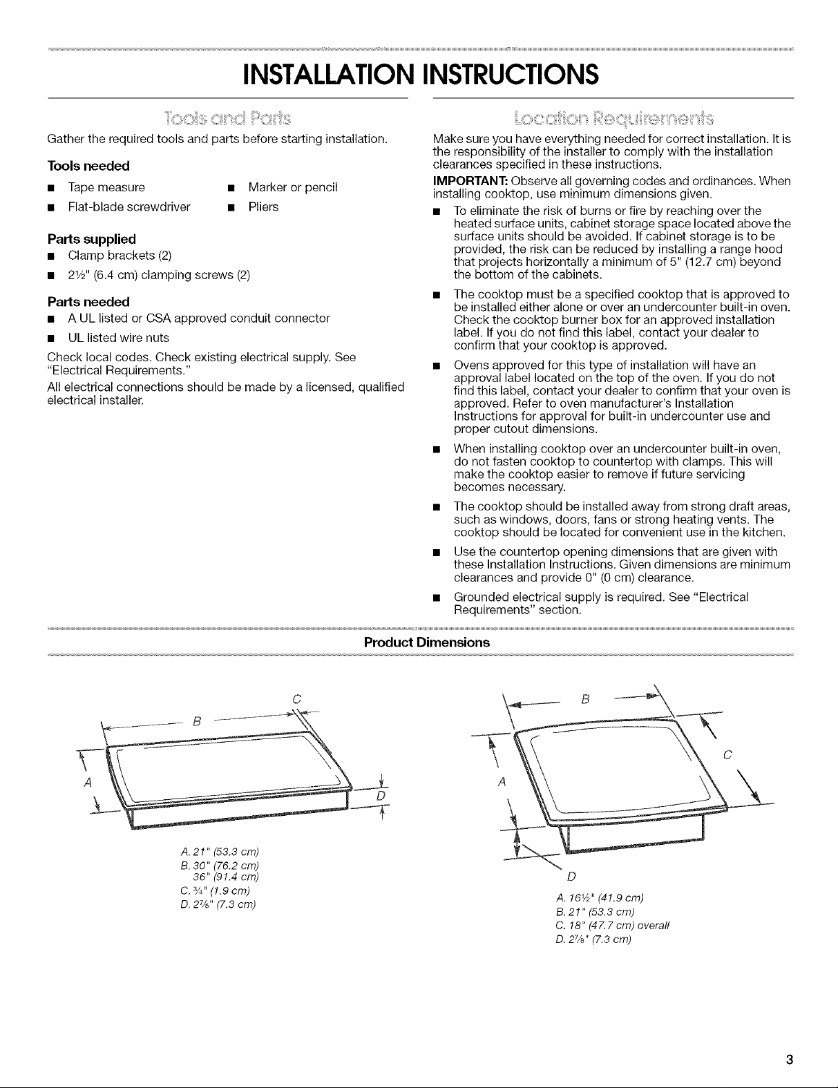
A. 21" (53.3 crn)
B. 30" (76.2 cm)
36" (91.4 cm)
C. %d' (1.g cm)
O. 27/8"(7.3 cm)
Product Dimensions
A. 16V2"(41.9 cm)
B. 21" (53.3 cm)
C. 18" (47.7cm) overall
O. 2%" (7.3 cm)
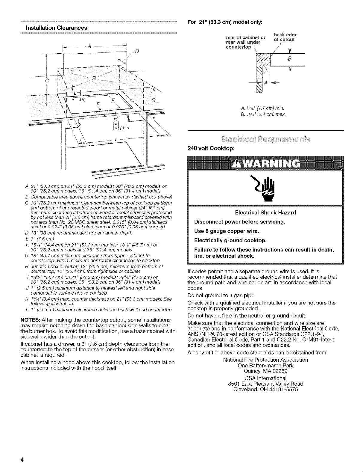
Installation Clearances
A. 21" (53.3 cm) on 21" (53.3 cm) models; 30" (76.2 cm) models on
30" (76.2 cm) models; 36" (91.4 cm) on 36" (91.4 cm) models
B. Combustible area above countertop (shown by dashed box above)
C. 30" (76.2 cm) minimum clearance between top of cooktop platform
and bottom of unprotected wood or metal cabinet (24" [61 cm]
minimum clearance if bottom of wood or me tal cabinet is protected
by not less than V4"[0.6 cm] flame retardant millboard covered with
not less than No. 28 MSG sheet steel, 0.015" [0.04 cm] stainless
steel or 0.024" [0.06 cm] aluminum or 0.020" [0.05 cm] copper)
D. 13" (33 cm) recommended upper cabinet depth
E. 3" (7.6 cm)
F. 15V2"(34.4 cm) on 21" (53.3 cm) models; 18%" (45.7 cm) on
30" (76.2 cm) models and36" (91.4 cm) models
G. 18" (45.7 cm) minimum clearance from upper cabinet to
countertop within minimum horizontal clearances to cooktop
H. Junction box or outlet," 12" (30.5 cm) minimum from bottom of
countertop; 10" (25.4 cm) from right side of cabinet
I. 18%" (33.7 cm) on 21" (53.3 cm) models; 287/8'' (47.3 cm) on
30" (76.2 cm) models; 35" (90.2 cm) on 36" (91.4 cm) models
J. 1" (2.5 cm) minimum distance to nearest left and right side
combustible surface above cooktop
K. 1%G"(3.4 cm) max. counter thickness on 21" (53.3 cm) models. See
following illustration.
L. 1" (2.5 cm) minimum clearance between back waft and countertop
NOTES: After making the countertop cutout, some installations
may require notching down the base cabinet side walls to clear
the burner box. To avoid this modification, use a base cabinet with
sidewalls wider than the cutout.
If cabinet has a drawer, a3" (7.6 cm) depth clearance from the
countertop to the top of the drawer (or other obstruction) in base
cabinet is required.
When installing a hood above this cooktop, follow the installation
instructions included with the hood itself.
For 21" (53.3 cm) model only:
rear of cabinet or of cutout
rear wall under
countertop
A. WI_" (1.7cm) min.
B. !5/16"(3.4 cm) max.
back edge
B
240 volt Cooktop:
Electrical Shock Hazard
Disconnect power before servicing.
Use 8 gauge copper wire.
Electrically ground cooktop.
Failure to follow these instructions can result in death,
fire, or electrical shock.
If codes permit and a separate ground wire is used, it is
recommended that a qualified electrical installer determine that
the ground path and wire gauge are in accordance with local
codes.
Do not ground to a gas pipe.
Check with a qualified electrical installer if you are not sure the
cooktop is properly grounded.
Do not have a fuse in the neutral or ground circuit.
Make sure that the electrical connection and wire size are
adequate and in conformance with the National Electrical Code,
ANSl/NFPA 70-latest edition or CSA Standards C22.1-94,
Canadian Electrical Code, Part 1 and C22.2 No. O-M91-1atest
edition, and all local codes and ordinances.
A copy of the above code standards can be obtained from:
National Fire Protection Association
One Batterymarch Park
Quincy, MA 02269
CSA International
8501 East Pleasant Valley Road
Cleveland, OH 44131-5575
Before You Make the Electrical Connection:
To properly install your cooktop, you must determine the type of
electrical connection you will be using and follow the instructions
provided for it here.
• A 4-wire or 3-wire, single phase, 240 volt, 60 Hz., AC only
electrical supply is required on a separate, 40-amp circuit,
fused on both sides of the line.
NOTE: The 15" (38.1 cm) model series requires a 20-amp
circuit.
• The cooktop should be connected directly to the junction box
through flexible, armored or nonmetallic sheathed, copper
cable. The flexible, armored cable extending from the fuse box
or circuit breaker box should be connected directly to the
junction box.
• Locate the junction box to allow as much slack as possible
between the junction box and the cooktop so that the cooktop
can be moved if servicing becomes necessary in the future.
• Do not cut the conduit. Use the length of conduit provided.
• A UL listed or CSA approved conduit connector must be
provided at each end of the power supply cable (at the
cooktop and at the junction box). A listed conduit connector is
already provided at the cooktop.
• If the house has aluminum wiring, connect the aluminum
wiring to the copper wire by using special connectors
designed and UL listed for joining copper to aluminum. Follow
the electrical connector manufacturer's recommended
procedure. Aluminum/copper connection must conform with
local codes and industry accepted wiring practices.
120 volt Cooktop:
For your personal safety, this cooktop must be grounded. This
cooktop is equipped with a power supply cord having a NEMA
5-20P, 3 prong grounding plug. To minimize possible shock
hazard, the cord must be plugged into a mating, NEMA 5-20R,
3 prong grounding-type outlet, grounded in accordance with
the National Electrical Code, ANSI/NFPA 70 latest edition, and
local codes and ordinances.
• If a mating outlet is not available, it is the personal
responsibility and obligation of the customer to have a
properly grounded, NEMA 5-20R, 3 prong outlet installed by a
qualified electrician.
WARNING: Improper connection of the equipment grounding
conductor can result in a risk of electric shock. Check with a
qualified electrician or serviceman if you are in doubt as to
whether the appliance is properly grounded. Do not modify the
plug provided with the appliance, if it will not fit the outlet, have a
proper outlet installed by a qualified electrician.
1. Remove the shipping materials and tape from the cooktop.
Remove the hardware package from inside the literature bag.
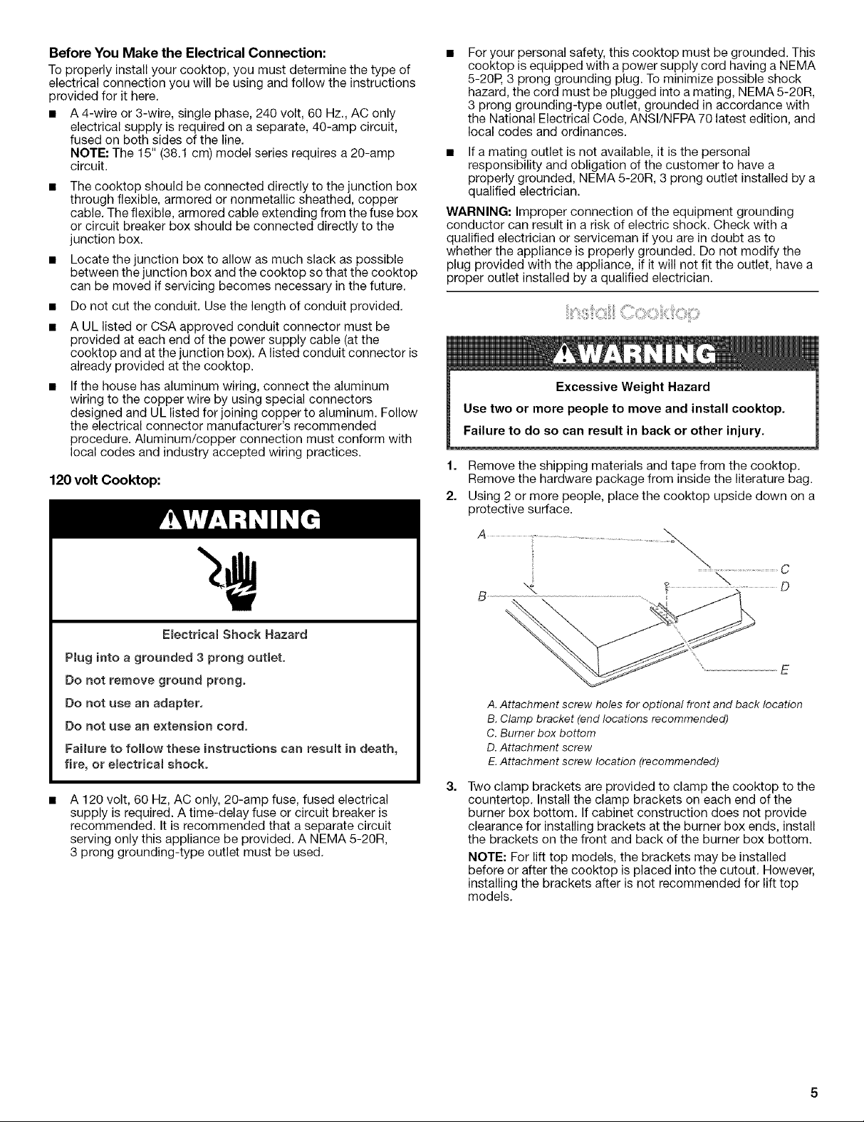
2. Using 2 or more people, place the cooktop upside down on a
protective surface.
Emectrica_ Shock Hazard
Plug into a grounded 3 prong outlet.
Do not remove ground prong.
Do not use an adapter.
Do not use an extension cord.
Failure to follow these instructions can result in death,
fire, or emectrical shock.
A 120 volt, 60 Hz, AC only, 20-amp fuse, fused electrical
supply is required. A time-delay fuse or circuit breaker is
recommended. It is recommended that a separate circuit
serving only this appliance be provided. A NEMA 5-20R,
3 prong grounding-type outlet must be used.
E
A. Attachment screw holes for optional front and back location
B. Clamp bracket (end locations recommended)
C. Burner box bottom
D. Attachment screw
E.Attachment screw location (recommended)
Two clamp brackets are provided to clamp the cooktop to the
countertop. Install the clamp brackets on each end of the
burner box bottom. If cabinet construction does not provide
clearance for installing brackets at the burner box ends, install
the brackets on the front and back of the burner box bottom.
NOTE: For lift top models, the brackets may be installed
before or after the cooktop is placed into the cutout. However,
installing the brackets after is not recommended for lift top
models.
 Loading...