

No. Parte 98017829 Rev. Rel.
Ampara los
siguientes
Modelos:
WF30215
NWF30745
WF30845
WF30945
NWF30312
NWF30322
NWF30714
NWF30724
NWF30905
WF30720
Im
preso en M
éxico 2005
STM
01199 Rev. Rel.
Part No. 98017829 Rev. Rel.
Covers
the following
models:
Printed in M
exico 2005
STM
01199 Rev. Rel.
www.whirlpool.vto.com
For questions about features,
operation/performance, parts, accessories
or service call:
01-800-83-004-00
or visit our web site at
Index......................................2
This guide contains useful information,
read it carefully.
www.whirlpool.vto.com
Para preguntas acerca de características,
operación, desempeño, accesorios
y servicio, llamar al:
01-800-83-004-00
o visite nuestra página de Internet
Indice..........................................2
Este manual contiene información útil, léalo
detenidamente antes de poner a funcionar
su estufa.
WF30215
NWF30745
WF30845
WF30945
NWF30312
NWF30322
NWF30714
NWF30724
NWF30905
WF30720
¡ Felicidades por la compra de su nueva estufa !
Índice
Partes y Características
Instalación
Conexión
Funcionamiento
Limpieza
Póliza de Garantía
Formato de Identificación
Centros de Servicio Autorizados
2
4
4
5
11
13
14
15
Acaba de adquirir un producto desarrollado
con las más avanzadas técnicas de diseño
y fabricación.
Le sugerimos que antes de usar su estufa
lea cuidadosamente las instrucciones de
este Manual, consérvelo ya que la
información contenida en el mismo será
importante para el buen funcionamiento de
su estufa durante muchos años.
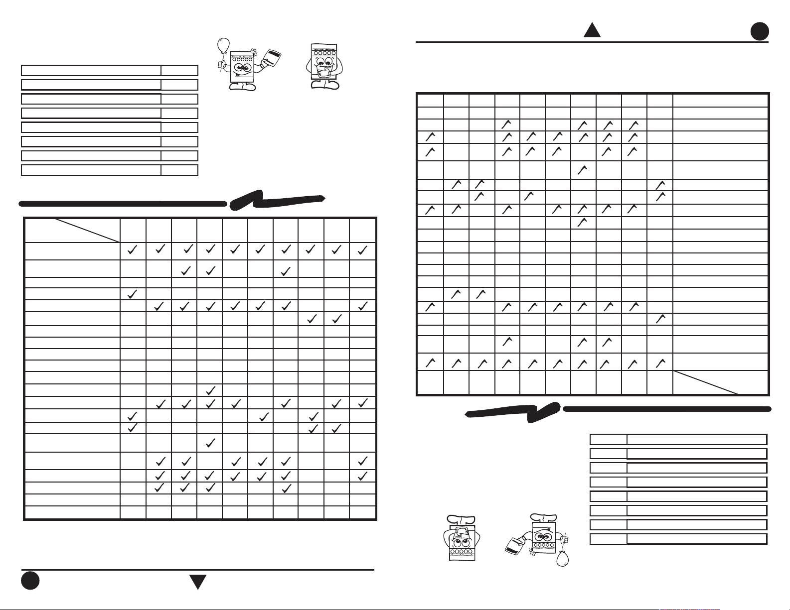
Partes y Características
Modelo
WF30215
NWF30745
Características
Respaldo Superior
Reloj
Porcelanizada
Cubierta Superior
Porcelanizada
Comal Porcelanizado
Comal de Aluminio con Antiadherente
Comal con Extensiones
Parrillas Superiores
Quemadores Superiores
Quemador Oval
Quemadores Multiposición
Super Quemador
Quemador Programable con Reloj
Termostato de Horno con Piloto
2
3
3
1
2
1
Termocontrol
Encendido Cerillo
Encendido Electrónico en Perilla
Quemadores Superiores
Encendido Electrónico Independiente
Quemadores Superiores
Interruptor Luz de Horno
Asador Inferior
11
Parrilla de Horno
Ventana de Horno
Panorámica
1
Panorámica
FABRICADO POR:
INDUSTRIAS ACROS WHIRLPOOL, S,A, DE C.V. Unidad Celaya
km 280
CARRETERA PANAMERICANA C.P. 38020, CELAYA, GTO.
Tel. 01(461)6185500
2
WF30845
Porcelanizada
3
Panorámica
WF30945
Porcelanizada
3
334
22
11
2
Panorámica
NWF30724
222
NWF30714
NWF30905
NWF30312
PorcelanizadaPorcelanizadaPorcelanizada Porcelanizada Porcelanizada
33322
44466
22222
EstandarPanorámicaExtragrande Extragrande
NWF30322
Estandar
WF30720
Porcelanizada
3
3
2
1
2
Panorámica
2
1
2
3
3
Panoramic
Porcelainized
WF30720
Standard
StandardPanoramicExtralarge Extralarge
PorcelainizedPorcelainizedPorcelainized Porcelainized Porcelainized
NWF30322
NWF30312
22222
44466
33322
NWF30905
222
NWF30714
CARRETERA PANAMERICANA C.P. 38020, CELAYA, GTO.
Panoramic3Panoramic
2
11
22
1
1
2
Panoramic
Panoramic
11
1
334
3
PorcelainizedPorcelainizedPorcelainized Porcelainized
NWF30724
WF30945
your range.
is important for best results in the use of
instructions in this manual, the information
Before you use your range, read the
quality requires maintenance.
it, you have received quality; but remember,
the latest technical expertise. By purchasing
This range was carefully manufactured with
WF30845
15
14
13
11
5
4
4
2
3
3
NWF30745
2
WF30215
Model
¡ Congratulations !
2
Tel. 01(461)6185500
km 280
INDUSTRIAS ACROS WHIRLPOOL, S,A, DE C.V. Unidad Celaya
MANUFACTURED BY:
Oven Window
Oven Rack
Broiler
Oven Light Switch
Surface Burners
Independent Electronic Ignition for
Knob for Surface Burners
Integrated Electronic Ignition in
Match Ignition
Thermocontrol
Oven Thermostat with Pilot
Programmable Burner with Clock
Super Burner
Multiposition Burners
Oval Burner
Top Burners
Top Grates
Griddle with extension
Aluminium Griddle with Antiadherent
Porcelainized Griddle
Cooktop
Clock
Backguard
Characteristics
Parts and Features
Authorized Service Centers
Identification Format
Warranty
Cleaning and Maintenance
How to Use Your Range
Gas Supply Connection
Installation
Parts and Features
Index
3
Instale su estufa en un lugar protegido de las inclemencias del tiempo y sobre una
superficie plana y resistente para soportar su peso.
No permita que la usen niños o personas que no conozcan su funcionamiento.
Proporciónele el mantenimiento adecuado.
Utilice la estufa solo en labores del hogar. No es un aparato de uso comercial.
3
Install your range in an area that is protected against weather exposure, on a level floor
strong enough to sustain its weight.
Do not allow range to be used by children or unqualified adults.
Provide for adequate maintenance.
Use the range only in home applications. It is not designed for commercial use.
127 V ± 10% 50/60 Hz 1,0 A Max.
Características eléctricas nominales:
Electric Characteristics:
127 V ± 10% 50/60 Hz 1,0 A Max.
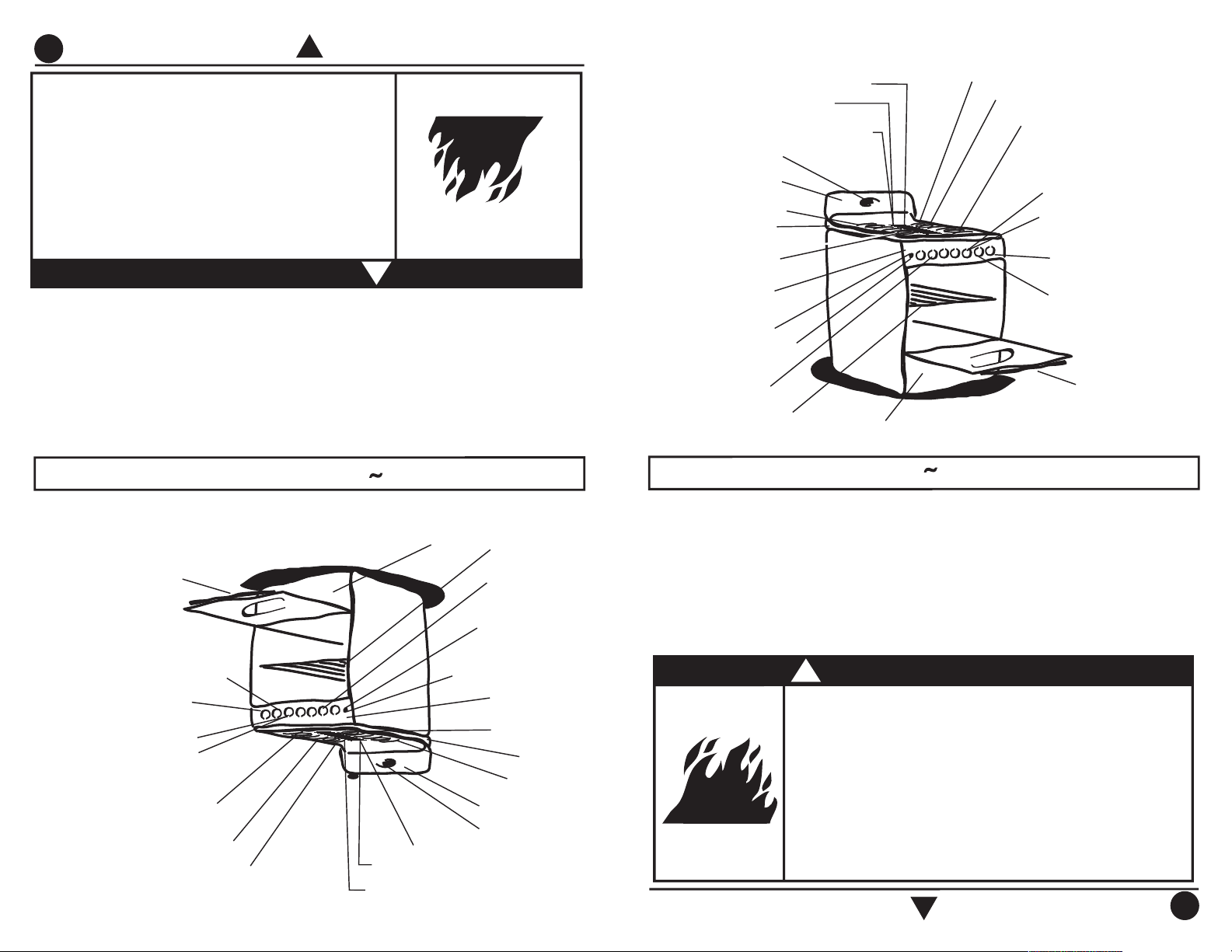
O
ven Therm
ostat w
ith Pilot
Top Burners
Porcelainized G
riddle
Backguard
Top G
rates
Burner Valves
O
ven Rack
O
ven W
indow
O
ven Light Sw
itch
Cooktop
Broiler
Independent Electronic
Ignition for Surface
Burners
Super Burner
Integrated Electronic
Ignition in Knob for Surface Burners
Program
m
able Burner
Clock
M
ultiposition Burners
O
val Burner
M
anifold Panel
Alum
inium
G
riddle w
ith Antiadherent
Therm
ocontrol
Term
ostato de Horno
con Piloto
Q
uem
adores Superiores
Com
al Porcelanizado
Respaldo Superior
Parrillas Superiores
Válvulas de
Q
uem
adores
Parrilla de
Horno
Ventana de Horno
Interruptor Luz de Horno
Cubierta Superior
Asador Inferior
Encendido Electrónico
Independiente para
Q
uem
adores Superiores
Super Q
uem
ador
Encendido Electrónico en
Perilla para Q
uem
adores
Superiores
Q
uem
ador Program
able
Reloj
Q
uem
adores M
ultiposición
Q
uem
ador O
val
Frente de Perillas
Com
al de Alum
inio con Antiadherente
Term
ocontrol
Fire or Explosion Hazard
Do not allow children to use or play with the range;
keep children away while range is in use.
Keep the range surroundings free of flammable material,
gasoline and other vapors or flammable liquids.
Do not get too close to the flame produced by the
burners or wear loose clothing; your clothes may ignite
if contact by open flames.
Do not use your range to warm rooms, because this is
dangerous.
Failure to do so can result in death, fire or explosion.
WARNING
!
Peligro de Incendio y/o Quemaduras
No permita que los niños usen o jueguen con la estufa;
manténgalos alejados mientras está en uso.
Mantenga los alrededores del aparato libres de materiales
combustibles, gasolina y otros vapores o líquidos flamables.
No se acerque demasiado a las flamas de los quemadores, ni
use ropa suelta, ya que se puede encender y causar quemaduras.
No use su estufa para calentar habitaciones, ya que esto es
peligroso.
No seguir estas instrucciones puede ocasionar incendio,
quemaduras o la muerte.
ADVERTENCIA
!
Com
al con extensiones
G
riddle w
ith extension
4
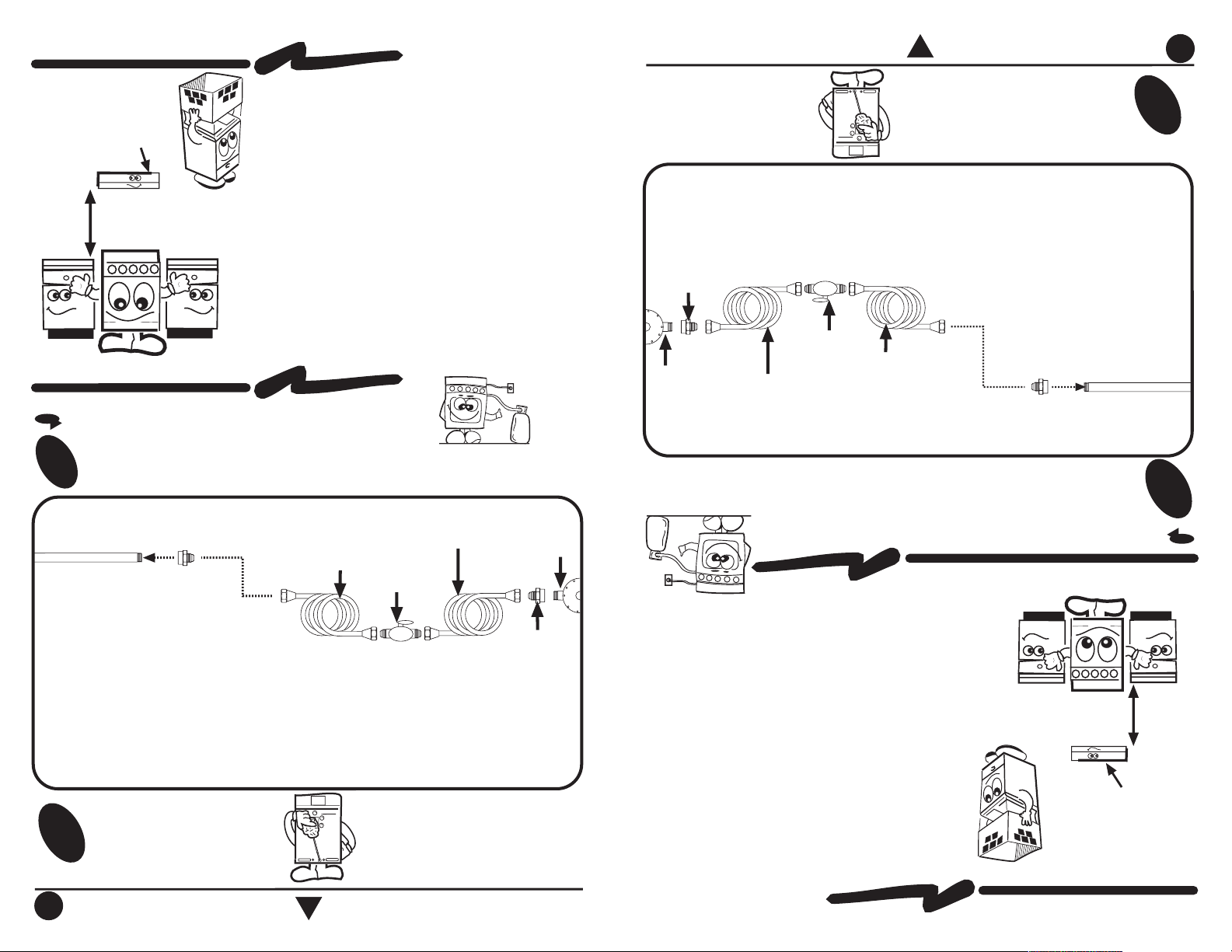
Conexión
4
Gas Supply Connection
GAS SUPPLY CONNECTION
CONEXIÓN DE LA ESTUF
A A LA LÍNEA DE GAS
Para conectar su estufa, utilice el material especificado en la figura
de abajo.
1
2
Cheque con agua jabonosa
que no existan fugas.
2
Check with soap solution for leaks.
To connect the range, use the material shown in the bottom figure.
1
Installation
EXHAUST DEVICE
61 cm
m
in.
Proper installation is your responsibility. A qualified
technician or Service technician must install this
range.
Remove all packing material and put the range
accessories in their places.
Select the best location in your kitchen for your
range, protected from wind and with enough space
to open the oven door.
Do not install cabinetry directly above the range.
If you will install an exhaust device, put it at 61 cm
minimum from the range cooktop.
If your range has a power cord, it must be installed
near an electrical wall outlet.
Do not use extension cords or multiple outlets.
Instalación
CAM
PANA EXTRACTO
RA
La instalación apropiada es su responsabilidad.
Un técnico calificado o un técnico de Servicio debe
instalar esta estufa.
Retire los elementos de empaque y coloque los accesorios
de la estufa.
Seleccione la mejor ubicación para su estufa, no debe
quedar expuesta a corrientes de aire y debe tener espacio
suficiente para abrir la puerta del horno.
No instale gabinetes o
muebles de cocina encima de la
estufa.
Si instala campana extract
ora, colóquela a 61 cm como
mínimo, de la cubierta de la estufa.
Si su estufa cuent
a con accesorios eléctricos, colóquela
cerca de un tomacorriente de pared.
No use extensiones eléctricas o contactos múltiples.
61 cm
m
ínim
o
NOTA: El m
aterial m
ostrado para instalacion no viene con la estufa.
NOTA: Su estufa puede estar equipada de fábrica con:
1.- Tubo de Alim
entacion ó
2.- Válvula de Corte de Gas.
Tubo de Alim
entación
integrado a la estufa
Llave de paso
de 9,5 m
m
(3/8")
Cople-Niple de 9,5 m
m
(3/8"NPT)
a 9,5 m
m
(3/8")cónica
Tubo de cobre con tuercas
cónicas de 9,5 m
m
(3/8")
Tubo de cobre con tuercas
cónicas de 9,5 m
m
(3/8") de
longitud necesaria para llegar
al gas
Cople-Niple de
9,5 m
m
(3/8"NPT)
Regulador
de gas
NOTE: The m
aterial shown for installation is not provided with the
range.
NOTE: The range could be equipped from the factory with
one of the following accesories:
1.- Gas Inlet Tube Fitting or
2.- Shut Off Gas Valve.
3/8" shut off
valve
G
as Inlet Tube Fitting
integrated to the range
3/8" NPT to 3/8" brass pipe
fitting Hex. adapter
3/8" copper pipe
with 5/8" flared
type nut
G
as
regulator
3/8" copper pipe with
5/8" flared type nut.
Necessary
length to reach the
gas
3/8" brass pipe
fitting
Hex. adapter
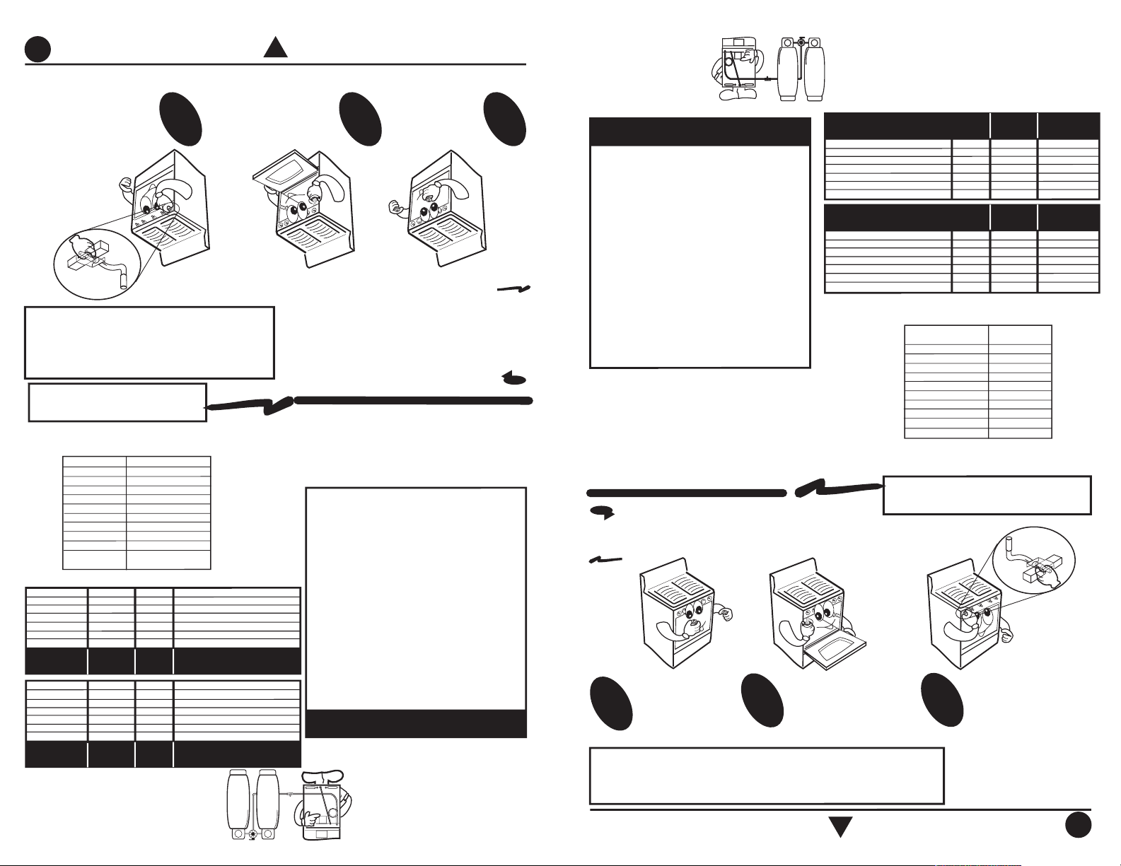
NOTA: Para operar esta estufa con gas natural, se
requiere el juego de conversión de acuerdo con la
siguiente tabla:
Este juego está disponible con su Centro de Servicio
Autorizado.
NOTE: To operate this range with natural gas, is required
a kit according
to the chart:
This kit is available at your nearest Authorized Service
Center.
5
Si la estufa presenta puntas amarillas en las flamas:
Retire las
perillas.
1
2
3
AJUSTE DE FLAMAS
Ajuste del aire de quemadores superiores:
IMPORTANTE
NOTA: Las diferentes altitudes sobre el nivel del mar y las variaciones
en el suministro de gas, hacen necesario regular la entrada de aire
primario a los quemadores para obtener una adecuada mezcla de
aire-gas y así tener un buen funcionamiento en la estufa.
Con el fin de facilitar el movimiento del aparato,
el instalador debe hacer una espiral con el tubo
flexible de cobre e instalar una llave de paso
en la línea de suministro de gas, esta llave debe
estar fuera de la estufa y accesible a las
personas que la usan.
Si la instalación no es
nueva, limpie los tubos
de cobre, para evitar
que se tapen las
espreas y/o pilotos.
5
If the range has yellow flames, it may
require adjustment to the air shutters:
Remove the
knobs.
1
2
3
HOW TO ADJUST THE FLAMES
How to adjust the air for surface burners:
IMPORTANT
NOTE:
Because of dif
ferent altitudes above
sea level and variations in the supply of gas,
you may need to adjust the main air intake
to the burners. This will result in a better
air-gas mixture and thus a better operation.
To make it easier to move the
appliance, the installer should
loop the 3/8" copper tubing as
shown in the illustration.
If the installation is not
new, you should clean
it in order to avoid the
obstruction of orifices
and/or pilots.
Esta estufa está preparada para
funcionar con gas L.P. de tanque
móvil o estacionario.
Para usarse con gas natural ( de
tubería) debe llamar a Servicio Acros
W
hirlpool para cam
biar las espreas
y hacer los ajustes necesarios, el
número telefónico aparece en la
página 15. El técnico calificado
debe cerciorarse que la conexión
no tiene fugas y que la presión de
gas en la estufa es la que aparece
en las tablas.
This range is adjusted at the factory
for use with L.P. gas.
To use this range with natural gas,
you must replace the surface and
oven burner orifices, call Servicio
Acros-Whirlpool, the phone number
is shown in the page 15. The
technician must make sure that the
connections have no leaks and the
gas pressure in the range is the
same as shown in the charts.
Retire el frente de
perillas quitando
los tornillos del
frente y de abajo
que lo sujetan.
Unscrew the screws
of front and below the
manifold panel and
remove it.
Empuje o jale los
reguladores
individualmente y
encienda los
quemadores hasta
obtener flamas azules
que no causen que la
flama se desprenda del
quemador.
Adjust the air shutters
individually. Light the
burner, then push or pull
the air shutter until you
get a blue flame that will
not cause the flame to
lift or blow off the burner.
Funcionamiento
NOTA:
No obstruya la salida de los
gases de combustion de horno o asador
How to Use Your Range
NOTE:
Do not obstruct the gas
exhaust of the oven or broiler
G
AS LP PRESIÓ
N DE O
PERACIÓ
N
2,75 kPa (28 cm
Col. agua)
Q
UEM
ADO
R
SUPERIO
R ESTAM
PADO
Q
UEM
ADO
R CENTRAL ESTAM
PADO
SUPERIO
R STD. ALUM
INIO
Q
UEM
ADO
R CENTRAL ALUM
INIO
SUPERIO
R SUPER ALUM
INIO
HO
RNO
ESPREA
68
68
68
66
64
57
m
m
0,787
0,787
0,787
0,838
0,914
1,092
kJ/h
6 800
6 800
7 000
7 900
9 500
13 600
DIAM
.
ESPREA
CAPACIDAD
TERM
ICA
ESPREA
58
58
58
56
55
52
m
m
1,067
1,067
1,067
1,181
1,321
1,613
kJ/h
6 800
6 800
7 000
7 900
9 500
13 600
DIAM
.
ESPREA
CAPACIDAD
TERM
ICA
G
AS NA
TURAL PRESIÓ
N DE O
PERACIÓ
N
1,76 kPa (18 cm
Col. agua)
QUEM
ADO
R
SUPERIO
R ESTAM
PADO
Q
UEM
ADO
R CENTRAL ESTAM
PADO
SUPERIO
R STD. ALUM
INIO
Q
UEM
ADO
R CENTRAL ALUM
INIO
SUPERIO
R SUPER ALUM
INIO
HO
RNO
NATURAL G
AS O
PERATING
PRESSURE 7 in W
ATER CO
LUM
N
(4,04 oz/squared inch)
NUM
BER
58
58
58
56
55
52
INCHES
0,042
0,042
0,042
0,046
0,052
0,063
BTU/h
6 500
6 500
6 700
7 500
9 000
13 000
O
RIFICE
DIAM
ETER
THERM
AL
CAPACITY
O
RIFICE
BURNER
UPPER STAM
PED
CENTRAL BURNER STAM
PED
UPPER STD ALUM
.
CENTRAL BURNER ALUM
.
UPPER SUPER ALUM
.
O
VEN
NUM
BER
68
68
68
66
64
57
LP G
AS O
PERATING
PRESSURE
11 in W
ATER CO
LUM
N
(6,36 oz/squared inch)
BURNER
UPPER STAM
PED
CENTRAL BURNER STAM
PED
UPPER STD ALUM
.
CENTRAL BURNER ALUM
.
UPPER SUPER ALUM
.
O
VEN
INCHES
0,031
0,031
0,031
0,032
0,036
0,043
BTU/h
6 500
6 500
6 700
7 500
9 000
13 000
O
RIFICE
DIAM
ETER
THERM
AL
CAPACITY
O
RIFICE
M
odelo W
F30215
98014528
M
odelo NW
F30745
98016217
M
odelo W
F30845
98016217
M
odelo W
F30945
98016217
M
odelo NW
F30724
98017391
M
odelo N
W
F30714
98017393
M
odelo N
W
F30905
98017391
M
odelo NW
F30312
98015083
M
odelo NW
F30322
98017459
M
odelo W
F30720 98016217
M
odel W
F30215
98014528
M
odel NW
F30745
98016217
M
odel W
F30845 98016217
M
odel W
F30945 98016217
M
odel NW
F30724
98017391
M
odel NW
F30714 98017393
M
odel NW
F30905 98017391
M
odel NW
F30312 98015083
M
odel NW
F30322 98017459
M
odel W
F30720 98016217
M
odel Range Kit Num
ber
No. de juego
M
odelo de estufa de conversión

6
Ajuste del aire del quemador del horno:
Retire la
parrilla del
horno (Ver
Pag. 10)
Retire la charola
del horno. (Ver
Pag. 11)
1
2
3
6
Los modelos con termostato tienen piloto en el horno,
para ajustarlo:
1.- Con el frente de perillas retirado, localice el tornillo de ajuste
de la flama del piloto, en el termostato. (Ver figura).
2.- Retire la charola del horno (ver Pag. 11), gire el control
aproximadamente 30° hasta sentir un tope,
(esta es la posición de piloto) y encienda el
piloto con un cerillo.
3.- Con un desarmador plano y delgado gire el tornillo de
ajuste del piloto hasta obtener una flama de
aproximadamente 1 cm.
4.- Coloque el frente de perillas, los tornillos y las perillas
nuevamente en su lugar.
Posición de Piloto.
A - Afloje el tornillo del
regulador.
B - Gire el regulador un
poco.
C - Encienda el horno.
D - Verifique que las
flamas sean azules.
E - Si las flamas no son
azules repita desde
el paso
B, al finalizar
apriete nuevamente
el tornillo.
F - Coloque la charola
del horno y la parrilla
nuevamente en su
lugar.
The models with thermostat have a pilot in the oven burner,
to adjust it:
1.- Without the manifold panel, locate the adjustment screw on
the thermostat, see the illustration on the right side.
2.- Remove the oven tray (see page 11) and turn the knob
approximately 30° until you feel a small stop,
turn the oven pilot on with a match or a lighter.
3.- With a flat and thin screwdriver turn the adjustment screw
until you get a flame approximately 3/8" tall.
4.- Replace the manifold panel, screws and knobs.
ADJUSTABLE FLAT SCREW
FO
R THE O
VEN PILO
T
Pilot Position.
How to adjust the oven burner air shutter:
Remove the
oven rack.
(See page 10).
Remove the oven
tray. (See page 11).
1
2
3
A - Locate the screw on
the air shutter and
loosen it.
B - Turn around the air
shutter.
C - Turn on the oven.
D - Verify that the flames
are blue.
E - If the flames are not
blue, repeat since
step
B, when the
flames are adjusted,
tighten the screw
again.
F - Replace the oven tray
and the oven rack.
OVEN WITH THERMOCONTROL
How to light the oven burner with thermocontrol, manually:
1.- Open the oven door, light a match and place
the flame at the igniter hole in the front of the
oven tray while you push in and turn the oven
knob 1/4 of the way, the burner will light
immediately.
2.- Verify that the oven burner has been ignited.
STM00563 R.0
Para encender el horno con termocontrol de
encendido manual:
1.- Encienda un cerillo y colóquelo cerca del
agujero de la charola del horno, al mismo
tiempo presione y gire 1/4 de vuelta la perilla
del horno.
2.- Verifique que el quemador del horno se haya
encendido.
ENCENDIDO MANUAL DE QUEMADORES DE HORNO
AP
AG
ADO
FLAM
A
M
ÍNIM
A
FLAM
A
M
ÁXIM
A
O
FF
M
INIM
UM
FLAM
E
M
AXIM
UM
FLAM
E
STM
00563 R.0
Para encender los quemadores superiores:
Acerque un cerillo encendido al quemador y al
mismo tiempo presione y gire 1/4 de vuelta la
perilla del quemador correspondiente.
ENCENDIDO MANUAL DE QUEMADORES
APAG
ADO
FLAM
A
M
ÍNIM
A
FLAM
A
M
ÁXIM
A
Perilla en posición de encendido.
HOW TO TURN ON THE BURNERS MANUALLY
To turn on the surface burners manually:
1.- Light a match and place it close the burner while you
push and turn the knob 1/4 of the way,the burner will
light immediatly. .
O
FF
M
INIM
UM
FLAM
E
M
AXIM
UM
FLAM
E
Knob on the m
ark of ignition.
TO
RNILLO
DE AJUSTE
DE PILO
TO
HO
RNO

7
FLAME
MINIMUM
FLAME
MINIMUM
OFF
OFF
Knob in ignition position.
BUTTON
ELECTRONIC IGNITION
FLAME
MAXIMUM
Knob on the mark of ignition.
FLAME
MAXIMUM
Programmable Burner
PROGRAMMABLE BURNER
maximum flame position.
2.- To stop the sparks turn the knob to the
desired knob to the ignition position. (See illustration).
integrated in knobs, to operate push and turn the
1.- Some models (see page 2) have electronic ignition
ignition in the knob:
To turn on the surface burners with electronic
TOP BURNERS WITH ELECTRONIC IGNITION
ENCENDIDO ELECTRÓNICO DE QUEMADORES SUPERIORES
valve to off position.
the gas will not leak due to the safety device, turn the
4.- When the burner turns off, the valve will remain open, but
off automatically and the beeper will sound.
3.- When the programmed time is over, the burner will turn
(Aprox. 10 seconds).
some more seconds until the burner remains on.
3 to 4 seconds until the burner lights, press the knob
turn it to the ignition mark, continue pushing the knob for
2.- Turn on the programmable burner, push the knob and
1 hour and 59 minutes, is how log the burner will run.
adjust the minutes with button. The time showing, up to
1.- Push the TIMER button, adjust the hour with button,
How to operate the programmable burner:
Para encender los quemadores superiores con
encendido electrónico en la perilla:
1.- Algunos modelos (ver Pag. 2) cuentan con encendido
electrónico en la perilla, para operarlo gire la perilla
del quemador que desea encender hasta la posición
de encendido, (ver figura).
2.- Para que la bujía de encendido deje de producir
chispas, gire la perilla hasta la posición de flama
máxima.
Para encender los quemadores superiores con encendido electrónico
independiente:
1.- Algunos modelos (ver Pag. 2) cuentan con
encendido electrónico independiente, para
operarlo oprima el botón que se localiza en el
lado izquierdo del frente de perillas y al
mismo tiempo presione y gire 1/4 de vuelta la
perilla del quemador que desea encender.
QUEMADOR PROGRAMABLE
Algunos modelos (ver Pag. 2) cuentan con quemador
programable. El quemador programable es un quemador
the right front side of the range.
range from 1:59 hours to 1 minute. The burner is located in
The programmable burner operates with the timer, with a
Some models (see page 2) include a programmable burner.
lights.
Release the ignition button when the burner
while you push and turn the desired knob.
located on the left side of the manifold panel
electronic ignition, to operate it push the button
Some models (see page 2) have independent
electronic ignition:
To turn on the surface burners with independent
que funciona según el tiempo que se le programe en el reloj
desde 1:59 horas hasta 1 minuto. Este quemador se localiza
en la parte frontal derecha de la estufa.
Quemador Programable
Para operar el quemador programable:
1.- Pulse la tecla TIMER (Quemador Programable) del reloj,
ajuste el tiempo que desea mantener encendido el
quemador, hasta 1:59 horas oprimiendo la tecla ó
0:59 minutos o menos oprimiendo la tecla .
2.- Encienda el quemador programable oprimiendo la perilla
y girándola hasta la posición de flama máxima, mantengala
oprimida por 3 ó 4 segundos hasta que el quemador
encienda, una vez encendido, mantenga la perilla
presionada hasta que el quemador permanezca encendido
cuando libere la perilla, (Aprox. 10 segundos).
3.- Cuando el tiempo del TIMER llegue a cero, el quemador
se apagará automáticamente y sonará indicando que el
tiempo se ha terminado.
4.- Al apagarse el quemador, la válvula quedará en posición
de abierto, el gas no se fugará debido al dispositivo de
seguridad, regrese la válvula a la posición de apagado.
FLAMA
MÁXIMA
Perilla en posición de encendido.
FLAMA
MÁXIMA
BOTÓN DE ENC.
ELECTRÓNICO
Perilla en posición de encendido.
FLAMA
MÍNIMA
FLAMA
MÍNIMA
7

MULTIPOSITION BURNERS
Some models (see page 2) have multiposition burners,
the position of these burners
can be changed, allowing
to concentrate the heat for large pots.
Some models have the multiposition
burners on the left side of the range.
To rotate the burners:
1.- Ensure that the burners are cold.
2.- Take the multiposition burners, lift and rotate them
180° (half turn).
3.- Put the burners down again,
be sure the spark plug
has been inserted in the burner hole.
8
Algunos modelos (ver Pag. 2) cuentan con termostato
y piloto de encendido en el horno, para operarlo:
1.- Encienda un cerillo y colóquelo cerca del agujero
de la charola del horno, presione y gire la perilla del
horno hasta la posición de piloto.
2.- Gire la perilla hasta 1/4 de vuelta para que encienda
el quemador.
3.- Verifique que el quemador del horno se haya
encendido.
HORNO CON TERMOSTATO Y PILOTO DE ENCENDIDO
If you want to cancel the time programming of the burner, push the
CLOCK button and turn off the burner.
If you want to reprogram the burner without turning it off, push the
CLOCK button and follow step 1.
The programmable burner also operates as a regular burner, if you
use this mode, you must turn off the burner manually.
The programmable burner control operates with electricity and will
turn off the burner if the electrical source fails.
Si desea cancelar la programación del quemador programable, pulse la tecla CLOCK y apague el
quemador.
Si desea reprogramar el tiempo del quemador sin apagarlo, oprima la tecla CLOCK y siga el paso 1.
El quemador con timer también funciona como un quemador normal. Si la opera en este modo
SÍ debe
cerrar la válvula manualmente al terminar de operarla.
El control del quemador con timer funciona con
electricidad, si el suministro de energía eléctrica llegara
a fallar cuando el quemador está programado, éste se apagará.
8
Some models (see page 2) have a thermostat and pilot
to control the oven function.
How to light the oven burner with thermostat and
pilot:
1.- Open the oven door, light a match and place the flame
at the igniter hole in the front of the oven tray, push
and turn the oven knob to the pilot position.
2.- Turn the oven knob 1/4 of the way to ignite the oven
burner, this position is minimum flame.
3.- Verify that the oven burner has been ignited.
OVEN WITH THERMOSTAT AND PILOT
Algunos modelos (ver Pag. 2) cuentan con quemadores
multiposición, estos quemadores se cambian de posición
permitiendo concentrar más calor para ollas grandes.
Algunos modelos tienen los quemadores
multiposición en el lado izquierdo de la
estufa.
Para girar los quemadores:
1.- Los quemadores deben estar fríos.
2.- Tome el quemador multiposición, levántelo y girélo
180° grados (media vuelta).
3.- Vuelva a colocarlo, asegurándose que la bujía de
encendido haya entrado en la perforación del quemador.
QUEMADORES MULTIPOSICIÓN
Algunos modelos tienen los quemadores
multiposición al centro de la estufa o en
los extremos.
Some models have the multiposition
burners on the center of the range or on
the sides.
Knob on the mark of ignition.
pilot
Perilla en posición de encendido.
piloto
BROIL
STM
00560 R.0
BROIL
STM
00560 R.0
Q
UEM
AD
O
RES
SIN
RO
TAR
QUEM
ADO
RES
RO
TADO
S
REG
ULAR
BURNERS
PO
SITIO
N
RO
TATED
BURNERS

9
9
Some models (see page 2) have broiler in the
bottom of the range.
To use the broiler you should turn on the oven
as indicated on page 8,
the knob must be as
shown in the figure. The oven should be empty.
Choose the position to use the broiler tray.
- Top position for broiling.
- Medium position for browning.
- Low position for melting.
Algunos modelos (ver Pag. 2) cuentan con
asador en la parte inferior de la estufa.
Para que el asador funcione debe encender
el horno como se indica en la Pag. 8, la perilla
debe estar en la posición que indica la figura.
El horno debe estar vacío.
Seleccione la posición donde desea utilizar
la charola.
- Posición alta para asar.
- Posición media para dorar.
- Posición baja para gratinar.
ASADOR
BROILER
Knob position to use the broiler.
Posición de la perilla para usar el
asador.
DIGITAL CLOCK / TIMER
RELOJ / TIMER DIGITAL
Algunos modelos cuentan con
reloj/ timer digital ( Ver pág. 2)
1. Boton del reloj
2. Pantalla
electrónica.
3. Botón para
aumentar
4. Botón para
reducir
5. Botón del
temporizador
Pantalla
Al conectar la elecricidad a la cocina por primera vez, aparecerá en la pantalla 12:00.
Cuando en cualquier otra ocación aparece 12:00 significa que ha ocurrido un corte de
elecricidad. Para volver a poner la hora en el reloj, vea la sección Clock (reloj)
Cuando el Temporizador no esta en uso la pantalla mostrara la hora del día.
Reloj
Éste es un reloj de 12 horas y no muestra a.m. o p.m.
Para poner la hora:
Antes de poner el reloj a la hora, asegúrese de que el temporizador se encuentre desactivado.
1. Presione CLOCK (reloj).
El indicador se encenderá intermitente cuando se esta programando el reloj.
2. Presione los botones con flechas hacia arriba ( ) o hacia abajo ( ) hasta que la
hora correcta del dia aparezca
en la pantalla. Se podrá
cambiar la hora haciendo el ajuste
por segundos o por intervalos de 10 minutos presionando el botón rápidamente o
presionándolo más largamente.
3. Presione CLOCK. El indicador intermitente se apagará indicando que se ha activado
el reloj.
Temporizador
El temporizador puede ser fijado en minutos y segundos
u horas y minutos hasta 11 horas
59 minutos, y hace la cuenta regresiva del tiempo fijado. El temporizador no pone en marcha
el horno ni lo detiene.
Para fijar:
1. Presione TIMER (temporizador)
La señal indicadora centelleará
durante la programación del temporizador.
2. Presione los botones con las flechas ( ) o ( ) para fijar la duración del tiempo.
3. Presione TIMER.
El temporizador comenzará a hacer la cuenta regresiva 5 segundos después de que se
ponga a funcionar.
Some models have Digital Clock/Timer
(See page 2)
1. Clock
2. Display.
3. Increase
4. Decrease
5. Timer
Display
When power is first supplied to the range, 12.00 will appear on the display.
Any other time 12:00 appears, a power failure has occurred.
Reset the Clock. See Clock section.
Any time the timer is not in use, the display will show the time of day.
Clock
This is a 12 hour clock and does not show a.m. or p.m.
To set:
Before setting, make sure the Timer is off.
1. Press CLOCK.
The colon will flash during Clock programming.
2. Press the up ( ) or down ( ) arrow pads to set the time of day.
The time can be changed in either small or 10 minute increments by pressing a pad briefly or by
pressing and holding a pad.
3. Press CLOCK. The colon will stop flashing when the Clock is active.
Timer
The Timer can be set in minutes and seconds or hours and minutes up to 11 hours, 59 minutes, and
counts down the set time. The Timer does not start or stop the oven.
To Set:
1. Press TIMER.
The colon will flash during Timer programming.
2. Press the ( ) or ( ) arrow pads to set length of time.
3. Press TIMER.
The timer will begin counting down 5 seconds after the time is set.
CLO
CK
TIM
ER
Tim
er
1
2
5
3
4
CLO
CK
TIM
ER
Tim
er
1
2
5
3
4
BROIL
STM
0
0560 R
.0
BROIL
STM
00560 R.0

10
10
COMAL DE ALUMINIO ANTIADHERENTE
Algunos modelos (ver Pág. 2) cuentan con comal de aluminio con acabado
antiadherente, para usarlo debe retirar una parrilla y colocarlo en lugar de ésta.
NOTA:
Use el comal de aluminio con FLAMA BAJA.
Para proteger el acabado es recomendable
poner un poco de aceite o mantequilla
antes de usarlo.
Use utensilios de plástico preferentemente a fin de protegerlo de rayaduras.
Use agua jabonosa y esponja para limpiarlo, materiales abrasivos como fibras de
plástico o metal pueden rayarlo.
ANTIADHERENT ALUMINIUM GRIDDLE
Some models (see page 2) have aluminium griddle with antiadherent finish, to use it remove
a top grate and put the griddle.
NOTE:
Use the griddle with MINIMUM FLAME.
Apply some butter before use the griddle to protect the finish.
Use plastic utensils to protect the griddle against scratches.
Do not use abrasive materials like steel or plastic fibres to clean it.
Use only cloth or sponge, soap or detergent and rinse with water.
COMAL
No use materiales abrasivos, fibras de plastico o metal para limpiarlo, use agua
jabonosa y una esponja.
PORCELAINIZED GRIDDLE
Do not use abrasive,plastic or metal material to clean it, use soap water and a sponge.
OVEN RACK
The oven has 4 different supports for the oven rack, this rack has a stop to avoid droping
from the oven, to change the rack position follow the steps:
To remove the oven rack:
1.- Pull the oven rack until it
stops.
2.- Lift the front part.
3.- Pull it again until it is
released.
To install the oven rack:
1.- Push the oven rack until it
stops.
2.- Lift the front part.
3.- Push it again until it stops.
An extra rack position is provided for special
cooking operations other than baking, such as
roasting, where a large roasting container will
require more heat and therefore need to be closer
to the heat source or oven bottom.
EXTRA RACK
PO
SITIO
N
Para retirarla de la estufa:
1.- Jale la parrilla hasta el tope.
2.- Levante la parrilla de la parte frontal.
3.- Jale nuevamente para liberarla.
Para instalarla en la estufa:
1.- Empuje la parrilla hasta el tope.
2.- Levante la parrilla de la parte
frontal.
3.- Empújela nuevamente para que
llegue hasta el fondo del horno.
PARRILLA DEL HORNO
Para hornear alimentos muy grandes puede
usarse el soporte extra de la parte inferior.
El horno tiene 4 diferentes soportes para la parrilla, la parrilla tiene un tope que evita
que se salga completamente del horno,
para cambiar la posició
n de la parrilla siga los
pasos:
SO
PO
RTE EXTRA
Para que aparezca en la pantalla
la hora del día mientras
el temporizador está haciendo
la cuenta regresiva, presione CLOCK. La hora del día aparecerá en la pantalla 5 segundos
antes de que el temporizador vuelva a hacer la cuenta regresiva.
Cuando falte un minuto de tiempo, la pantalla comenzará la cuenta regresiva en segundos.
Cuando el temporizador llegue a cero, la pantalla mostrará End (fin) y se escucharán
cuatro señales audibles de un segundo.
Para anular:
Presione TIMER dos veces en el modo de temporizador.
To display the time of day while the Timer is counting down, press CLOCK. Time of day will be
displayed 5 seconds before returning to the Timer countdown.
When there is one minute of time remaning the display will begin counting down in seconds.
When the time reach zero the display will show END and four 1-seconds tones will sound.
To cancel:
Press TIMER twice in the Timer mode.

11
11
LUZ DE HORNO
Algunos modelos (ver Pag. 2),
cuentan con luz en el
horno, la iluminación es importante para revisar el
horneado sin abrir la puerta.
Algunos modelos tienen el interruptor en el lado
izquierdo del frente de perillas. Otros lo tienen integrado
en la perilla del horno, misma que al girarla, enciende
la luz y se mantiene encendida durante el horneado,
asegurándole observar sus alimentos en cualquier
momento. Otros modelos lo tienen integrado frente a
la puerta del horno y se acciona automáticamente al
abrir la puerta del mismo.
NOTA: El cable tomacorriente debe conectarse a una
toma de corriente con un voltaje de 127 V ± 10%.
Cerciórese de que la
instalación esté apropiadamente
aterrizada.
OVEN LIGHT
Some models (see page 2) have an oven light.
Some models have the light switch located on
the left side of the manifold panel. Other models
have the switch integrated on the oven knob, it
turns on when the knob is operated and the light
remains on, allowing to watch the baking at any
time. Other models have an integrated light switch
in front of the oven door and is activated
automatically when the door is opened.
How to replace the oven bulb:
1.- Disconnect the power cord.
2.- Remove the bulb and replace with a new 40
watts special appliance bulb.
3.- Connect the power cord again.
NOTE:
Connect the range in a wall outlet with a voltage of
127 V
±
10%. Be sure the installation is properly grounded.
Para reemplazar el foco del horno:
1.- Desconecte el cable tomacorriente de
la estufa.
2.- Retire el foco y reemplácelo con un
foco nuevo de 40 watts especial para
aparatos domésticos.
3.- Conecte la estufa nuevamente.
Cleaning and Maintenance
Regularly clean grates, burners, co
oktop and the oven tra
y, use water,
soap and a damp cloth, avoid using abrasive or sharp objects. Periodically
clean the gap between the cooktop and the manifold panel.
Your range has the
Continuous Cleaning System
in the oven, it is
not necessary to clean the walls of the oven, the spills will burn
each time you bake.
How to remove the oven tray:
1.- Take the tray by the side holes.
and lift the rear side.
2.- Push the tray towards the top and
back of the oven.
3.- Pull the tray out the oven.
Do not use caustic soda or cleaning
agents which contain it to clean the
range.
Failure on following the above, will
permanently damage the surfaces
where it is applied.
IMPORTANT
Limpieza
Es necesaria la limpieza periódica de la estufa, use agua, jabón y un trapo húmedo, no
use fibra metálica, porque se ralla el esmalte. Limpie regularmente el hueco entre la
cubierta superior y el frente de perillas.
Su estufa cuenta con el
Sistema de Autolimpieza
en el horno (acabado rugoso), no es
necesario que limpie las paredes, ya que con cada horneado se van quemando los residuos
de alimentos que se van salpicando.
Como retirar la charola del horno:
1.- Tome la charola de las ranuras laterales.
y levántela de la parte trasera.
2.- Empuje la charola hacia adentro del
horno para destrabarla.
3.- Jale la charola para sacarla.
No utilice sosa cáustica o productos
de limpieza que la contengan para
limpiar la estufa.
De no seguir esta instrucción se
ocasionarán daños permanentes en las
superficies donde se aplique.
IMPORTANTE

12
12
ELECTRICAL DIAGRAMS
For your safety
Do not store gasoline
or other flamable
liquids near to your
range.
Make sure that the
furniture near to your
range, as well as the
wall and the floor must
support a temperature
of 180
o
C to avoid any
deformation.
Do not obstruct the
side grooves in the
oven tray.
Failure to follow the
above precautions
may result in death,
fire or explosion.
For your safety
IF YOU SMELL GAS:
Open the windows.
Do not activate any
light switch.
Close the gas line
supply and the
connection shut off
valve.
I
mmediately call your
authorized repair
service or your gas
supplier.
Failure to follow the
above precautions
may result in fire or
explosion.
WARNING
!
WARNING
!
DIAGRAMAS ELÉCTRICOS
Para su seguridad:
No almacene gasolina
u otros fluidos
flamables en la
cercanía de su aparato.
Asegúrese que los
muebles cercanos a
su estufa, así como el
muro y piso soporten
una temperatura de
180°C, para que no
sufran deformaciones.
No obstruya las
ranuras de la charola
del horno.
No seguir estas
instrucciones puede
ocasionar riesgo de
fuego o explosión o la
muerte.
Para su seguridad:
Si huele a gas
Abra las ventanas.
No toque interruptores
eléctricos.
Apague todas las
flamas cerrando la
válvula general de
paso.
Llame inmediatamente
a la central de fugas o
a su proveedor de gas.
No seguir estas
instrucciones puede
ocasionar riesgo de
fuego o explosión.
ADVERTENCIA
!
ADVERTENCIA
!
Foco de Horno 40 W
.
Diagram
a Eléctrico Estufa con Luz en el Horno y
Encendido Electrónico con Interruptor Independiente.
M
ódulo de Encendido
4, 6 u 8 salidas.
Interruptor Luz de Horno e Interruptor M
ódulo de
Encendido Integrados
N
L1
Electrical Diagram
Range w
ith O
ven Light and
Electronic Ignition w
ith Independent Sw
itch.
O
ven B
ulb 40 W
Ignition M
odule.
Integrated O
ven Light Sw
itch & Electronic Ignition
Sw
itch
N
L1

13
13
WHIRLPOOL MEXICO, S.A. DE C.V.
Antigua Carretera a Roma km 9, Col. Milagro, Apodaca, N.L., Mexico, C.P.
66600, phone (81)83-29-21-00,
in the terms of this policy, we warranty to the
buyer and the consumer of this range identified in this following policy:
COVERED CONCEPTS:
Manufacturing defects that hinder total or partially the correct performance
of the appliance. Repair, change of pieces and components.
Handwork and transportation expenses derived from the fulfillment of the
warranty, within our service net. The prev
ious points will be made without any
cost for the consumer.
NOT COVERED CONCEPTS:
- When the range is used in other than normal, single family household use.
- When the range is not used according to the use and care guide attached.
- When the range has been repaired by unauthorized service.
PROCEDURE TO MAKE EFFECTIVE THE WARRANTY:
The procedure to use this warranty if you consider one of the events above
has occurred. Contact one of the authorized service centers listed in this
manual.
TERMS:
This warranty covers ONE YEAR beginning the day the buyer or consumer
receives the range to his satisfaction.
WARRANTY
WHIRLPOOL MEXICO, S.A. DE C.V.
Antigua Carretera a Roma km 9, Col. Milagro, Apodaca, N.L., México,
C.P. 66600, Tel. (81)83-29-21-00,
en los términos de esta póliza, garantiza al comprador
de la estufa identificada en la presente póliza, exclusivamente lo siguiente:
CONCEPTOS CUBIERTOS POR LA GARANTÍA:
Defectos de fabricación que impidan total o parcialmente el correcto funcionamiento
de la estufa, que se presenten dentro del término de vigencia de esta garantía.
Reparación, cambio de piezas y componentes.
Mano de obra y gastos de transportación derivados del cumplimiento de la garantía,
dentro de nuestra red de servicio.
Los puntos anteriores se harán sin costo alguno para el Consumidor.
CONCEPTOS NO CUBIERTOS POR LA GARANTÍA:
- Cuando el producto ha sido utilizado en condiciones distintas a las normales (la
estufa no es para uso comercial o industrial).
- Cuando el producto no ha
sido operado de acuerdo con el
instructivo de instalación
y uso de la estufa.
- Cuando el producto ha sido alterado o reparado por personas o establecimientos
no autorizados por Servicio Acros-Whirlpool.
PROCEDIMIENTO PARA HACER EFECTIVA LA GARANTÍA:
Al considerar el comprador que ha ocurrido alguno de los eventos amparados por
esta póliza, deberá ponerse en contacto con alguno de los establecimientos indicados
en la lista de Centros de Servicio Autorizados, aquí incluida.
Esta garantía quedará sin efecto cuando personas o establecimientos no autorizados
intervengan en la reparación o reemplazo de componentes de fabricación.
TÉRMINO:
Esta garantía tiene una vigencia de UN AÑO a partir de la fecha en que el consumidor
reciba de conformidad la estufa.
PÓLIZA DE GARANTÍA
Electronic Ignition Sw
itch on Knobs
(according to m
odel).
O
ven Light Sw
itch on Door
(according to m
odel).
O
ven Bulb 40 W
(according to m
odel).
M
odule 4, 6, or 8 outlets
(according to m
odel).
O
ven Light Sw
itch on Therm
ostat (according to m
odel).
Independent Electronic Ignition Sw
itch
(according to m
odel).
Clock
Valve
Term
ocouple
L
N
Burner w
ith Tim
er, Electronic Ignition Sw
itch
(according to m
odel).
Bidirectional Therm
ostat, Electronic
Ignition Sw
itch (according to m
odel).
Program
m
able Burner Valve
(according to m
odel).
Range w
ith Electronic Ignition
O
ven Light Sw
itch
on M
anifold Panel
(according to m
odel).
Clock/Tim
er
(Som
e m
odels)
Interruptor de Encendido Electrónico en Perilla
(según m
odelo).
Interruptor Luz de Horno en Puerta
(según m
odelo).
Foco de Horno 40 W
(según m
odelo).
M
ódulo de Encendido
4, 6 u 8 salidas (según m
odelo).
Interruptor Luz H
orno en Term
ostato (según m
odelo).
Interruptor de Encendido Electrónico Independiente
(según m
odelo).
Reloj
Válvula
Term
opar
L
N
Interruptor del Q
uem
ador con Tim
er
para Encendido Electrónico (según m
odelo).
Interruptor Term
ostato Bidireccional
para Encendido Electrónico (según m
odelo).
Válvula de Q
uem
ador Program
able
(según m
odelo).
Estufa con Encendido Electrónico .
Interruptor Luz de
H
orno en Frente
Perillas
(según m
odelo).
Reloj/Tim
er
(según m
odelo)

FORMATO DE IDENTIFICACIÓN
N
OMBRE DEL COMPRADOR ______________________________________
DOMICILIO_________________________ TEL. ______________________
NOMBRE DEL DISTRIBUIDOR _____________________________________
DOMICILIO __________________________ TEL. ______________________
Phone number 01-800-83-004-00
Use without charge the Nationwide Consumer Assistance Center
Call free in Mexico
SERVICIO ACROS-WHIRLPOOL
with the proper bill of sale or invoice.
In case of loss of policy, the dealer will issue a new one,
WHERE THE PRODUCT WAS PURCHASED.
COVERED BY THIS POLICY FROM THE DEALER
THE CONSUMER CAN REQUEST THE WARRANTY
14
PRODUCTO____________ MARCA_______ MODELO _________________
NO. DE SERIE ________________FECHA DE ENTREGA________________
FIRMA DEL DISTRIBUIDOR Y SELLO REPRESENTANTE AUTORIZADO
(Señale con precisión calle, número exterior o interior;
colonia, ciudad, estado y C.P.)
NOTA IMPORTANTE
Este documento deberá ser presentado para cualquier
trámite relacionado con la garantía de productos adquiridos
dentro de la República Mexicana, si usted compró su
producto en otro país, acuda a la casa
comercial/distribuidor donde fué adquirido.
EL COMPRADOR DEBERÁ MANTENER ESTE
DOCUMENTO EN SU PODER Y EN UN LUGAR
SEGURO.
El consumidor podrá solicitar que se haga efectiva la
garantía que ampara esta póliza, ante la casa comercial
donde se adquirió el producto. En caso de extravío de la
póliza mencionada, el proveedor expedirá una nueva
póliza de garantía, previa presentación de la nota de
compra o factura respectiva.
SERVICIO ACROS-WHIRLPOOL
Dentro de la República Mexicana
Utilice sin cargo para usted el Servicio Nacional Clientes
Teléfono 01-800-83-004-00
warranty.
Republic, ask your authorized dealer to make valid your
Republic. If you bought your range out of the Mexican
with this warranty for products acquired in the Mexican
This document must be shown in any transaction related
IMPORTANT NOTE
(Indicate precise steet, col. state and zip code).
DEALER SIGNATURE AND STAMP AUTHORIZED REPRESENTATIVE
SERIAL NUMBER ________________DELIVERY DATE__________________
PRODUCT _____________TRADEMARK________ MODEL ______________
ADDRESS ________________________ PHONE ______________________
DEALER NAME__________________________________________________
ADDRESS________________________ PHONE ______________________
_____________________________________________
CONSUMER NAME
IDENTIFICATION FORMAT
14

15
15
For your convenience, we have a wide network of authorized
service center throughout the country. Dial toll free:
01 800 8 300 400
www.saw.com.mx
ACAPULCO
, G
RO
.
Phone 01-800-8 300 400
Av. Constituyentes No. 39
Col. Vista Alegre
AG
UASCALIENTES, AG
S.
Phone 01-800- 8 300-400
Héroe de Nacozari No. 2528 Sur
Fracc. Jardines del Parque
CHIHUAHUA, CHIH.
Phone (614) 417-4978 and 419-80-00
Av. Vallarta No. 4918
Col. Las G
ranjas
CUERNAVACA, M
O
R.
Phone 01-800-8 300-400
M
orelos Sur 1001 L. 209
Col. Las Palm
as
CULIACÁN, SIN.
Phone (667) 716-8390 and 716-8379
M
ariano Escobedo No. 1031 O
te.
Col. Las Vegas
Esq. c/ Cuauhtém
oc
G
UADALAJARA, JAL.
Phone 01-800-8 300-400
Río Conchos No. 1765
Fracc. Ind. del Rosario
Sector Reform
a
HERM
O
SILLO
, SO
N.
Phone (662) 210-4680 and 215-9413
Ignacio Hdz. 282
Col. Balderram
a
JUÁREZ, CHIH.
Phone 01-800-8 300-400
Sor Juana Inés de la Cruz No. 168
Col. San Lorenzo
LEÓ
N, G
TO
.
Phone (477) 770-90-50 and 51
Pino Suárez No. 512
Col. Centro
LO
S M
O
CHIS, SIN.
Phone (668) 818-08-17 and 818-08
18
Belisario Dom
ínguez No. 351 Nte.
Col. Centro
M
ÉRIDA, YUC.
Phone (999) 928-1038 and 928-61-
66
Calle 55 No. 466
Por 54 y 56 Col. Centro
M
ÉXICO
, D.F.
Phone (55) 52 78- 67 00
Calle 2 Poniente No. 11
Col. San Pedro de los Pinos
M
INATITLÁN, VER.
Phone (922) 223-7193 and 223-
7031
Av. Lerdo No. 41
Col. Centro
M
O
NTERREY, N.L.
Phone (81) 8329-2100
Centro Industrial Acros W
hirlpool
Carr. M
iguel Alem
án Km
. 16,6
Apodaca, N.L.
M
O
RELIA, M
ICH
Phone (443) 324-4221
O
bragueros de Nurio No. 194-C
Col. Vascos de Q
uiroga
PUEBLA, PUE.
Phone 01-800-8 300-400
Calle 24 Sur No. 3532
Col. Santa M
ónica
Q
UERÉTARO
, Q
RO
.
Phone (442) 212-37-66
W
enceslao de la Barquera
No. 22-C
Col. Cim
atario
REYNO
SA, TAM
PS.
Phone (899) 920-0290
Am
ado Nervo No. 700-C
Col. Cavazos
TAM
PICO
, TAM
PS.
Phone (833) 219-2620 and 219-2621
Av. Hidalgo No. 1215
Col. M
octezum
a
TO
RREÓ
N, CO
AH.
Phone (871) 718-6565 and 718-6464
Calzada Cuauhtem
oc 1047 Nte.
Col. Centro
TIJUANA, B.C.
Phone 01-800-8 300-400
Blvd. Agua Caliente No. 105-6
Col. Centro
VERACRUZ, VER.
Phone (229)932-7335 and 932-
7358
Av. 20 de Noviem
bre No. 533-2
Col. Centro
VILLAHERM
O
SA, TAB.
Phone 01-800-83-00400
Astrólogos No. 112
Col. G
aviotas Sur
TUXTLA G
TZ, CHIS.
Phone (961) 612 8554
Novena O
te. Sur No. 555
Col. Centro
Follow are listed our exclusive service centers, if you need
assistance or spare parts, call the nearest service center
where you will be assisted by qualified technicians.
En otras ciudades de la República Mexicana llame sin costo al
01 800 8 300 400
www.saw.com.mx
ACAPULCO
, G
RO
.
Tel. 01-800-8 300 400
Av. Constituyentes No. 39
Col. Vista Alegre
AG
UASCALIENTES, AG
S.
Tel. 01-800- 8 300-400
Héroe de Nacozari No. 2528 Sur
Fracc. Jardines del Parque
CHIHUAHUA, CHIH.
Tel. (614) 417-4978 y 419-80-00
Av. Vallarta No. 4918
Col. Las G
ranjas
CUERNAVACA, M
O
R.
Tel. 01-800-8 300-400
M
orelos Sur 1001 L. 209
Col. Las Palm
as
CULIACÁN, SIN.
Tels. (667) 716-8390 y 716-8379
M
ariano Escobedo No. 1031 O
te.
Col. Las Vegas
Esq. c/ Cuauhtém
oc
G
UADALAJARA, JAL.
Tel. 01-800-8 300-400
Río Conchos No. 1765
Fracc. Ind. Del Rosario
Sector Reform
a
HERM
O
SILLO
, SO
N.
Tels. (662) 210-4680 y 215-9413
Ignacio Hdz. 282
Col. Balderram
a
JUÁREZ, CHIH.
Tel. 01-800-8 300-400
Sor Juana Inés de la Cruz No. 168
Col. San Lorenzo
LEÓ
N, G
TO
.
Tel. (477) 770-90-50 y 51
Pino Suárez No. 512
Col. Centro
LO
S M
O
CHIS, SIN.
Tels. (668) 818-08-17 y 818-08-18
Belisario Dom
ínguez No. 351-Nte.
Col. Centro
M
ÉRIDA, YUC.
Tel. (999) 928-1038 y 928-61-66
Calle 55 No. 466
Por 54 y 56 Col. Centro
M
ÉXICO
, D.F.
Tel. (55) 52 78- 67 00
Calle 2 Poniente No. 11
Col. San Pedro de los Pinos
M
INATITLÁN, VER.
Tels. (922) 223-7193 y 223-7031
Av. Lerdo No. 41
Col. Centro
M
O
NTERREY, N.L.
Tels. (81) 8329-2100
Centro Industrial Acros W
hirlpool
Carr. M
iguel Alem
án Km
. 16,6
Apodaca, N.L.
M
O
RELIA, M
ICH
Tel. (443) 324-4221
O
brageros de Nurio No. 194-C
Col. Vasco de Q
uiroga
PUEBLA, PUE.
Tel. 01-800-8 300-400
Calle 24 Sur No. 3532
Col. Santa M
ónica
Q
UERÉTARO
, Q
RO
.
Tel. (442) 212-37-66
W
enceslao de la Barquera
No. 22-C
Col. Cim
atario
REYNO
SA, TAM
PS.
Tel. (899) 920-0290
Am
ado Nervo No. 700-C
Col. Cavazos
TAM
PICO
, TAM
PS.
Tels. (833) 219-2620 y 219-2621
Av. Hidalgo No. 1215
Col. M
octezum
a
TO
RREÓ
N, CO
AH.
Tels. (871) 718-6565 y 718-6464
Calzada Cuauhtém
oc 1047 Nte.
Col. Centro
TIJUANA, B.C.
Tels. 01-800-8 300-400
Blvd. Agua Caliente No. 105-6
Col. Centro
VERACRUZ, VER.
Tels. (229)932-7335 y 932-7358
Av. 20 de Noviem
bre No. 533-2
Col. Centro
VILLAHERM
O
SA, TAB.
Tels. 01-800-83-00400
Astrólogos No. 112
Col. G
aviotas Sur
TUXTLA G
TZ, CHIS.
Tel. (961) 612 85 54
Novena O
te. Sur No. 555
Col. Centro
A continuación se enlistan nuestros centros de servicios
exclusivos, si requiere asistencia, partes o refacciones
llame al centro de servicio mas cercano a su domicilio en
donde será atendido por personal altamente calificado.

NOTA:
16
16
NOTE:
 Loading...