

Page 1
No. Parte W10216838 Rev. C
stm02601 Rev. C
NWF0600
NWF0601
NWF0602
NWF2900
NWF2901
NWF5900
Ampara los
siguiente
Modelos:
Índice..........................................2
Este manual contiene información útil, léalo
detenidamente antes de poner a funcionar
su estufa.
Cover
the following
models:
Index......................................2
This guide contains useful information,
read it carefully.
Manual
NWF0600
NWF0601
NWF0602
NWF2900
NWF2901
NWF5900
Part No. W10216838 Rev. Cstm02601 Rev. C
Page 2
Partes y Características
2
Parts and Features
2
FABRICADO POR:
INDUSTRIAS ACROS WHIRLPOOL, S,A, DE C.V. Unidad Celaya
km 280
CARRETERA PANAMERICANA C.P. 38020, CELAYA, GTO.
Tel. 01(461)6185500
MANUFACTURED BY:
INDUSTRIAS ACROS WHIRLPOOL, S,A, DE C.V. Unidad Celaya
km 280
CARRETERA PANAMERICANA C.P. 38020, CELAYA, GTO.
Tel. 01(461)6185500
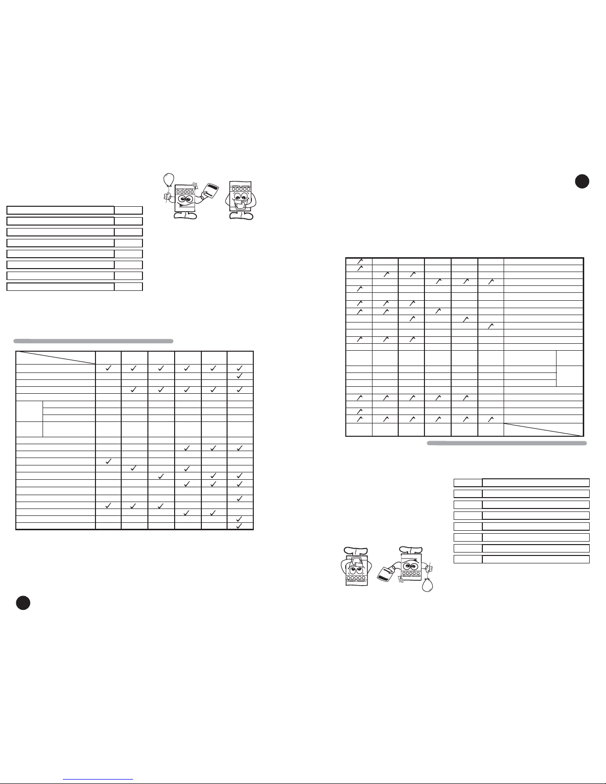
Modelo
Características
NWF0600
Manual
3
Porcelanizada
Manual
NWF0601
3
Porcelanizada
2
NWF0602 NWF2900 NWF2901 NWF5900
Respaldo Superior
Reloj
Parrillas Superiores
Comal de Sobreponer
Cubierta
Quemador
Estampado
Encendido Quemadores Superiores
Perilla de Seguridad
Encedido Horno
Termocontrol
Termocontrol 5 pasos
Termostato simple
Luz de horno
Parrilla de horno
Parrillas Deslizables
Ventana de Horno Estandar
Ventana de Horno Extra Larga
Quemador
de Aluminio
Ventana de Horno Panoramica
Asador
2
1
66666
Manual Manual Elect. Elect. Elect.
1
2
Manual
3
Porcelanizada
2
3
Porcelanizada
2
Manual
3
Porcelanizada
2
3
Porcelanizada
Quemador tamaño Estandar
Superquemador
Quemador alargado
Quemador tamaño
Estandar con Tapa
de Laton
Thermocontrol 5 Steps
Upper Burners Ignition
Backguard
Model
Characteristics
NWF0600
Manual
3
Porcelanized
Manual
NWF0601
3
2
NWF0602 NWF2900 NWF2901 NWF5900
Clock
Top Grates
Over Grate Griddle
Cooktop
Stamped
Burner
Safe Knobs
Oven Ignition
Thermocontrol
Simple thermostat
Oven light
Oven Racks
Slide out Oven Rack
Standard Window
Extra Large Window
Aluminum
Burner
Panoramic Door
Broiler
2
1
66666
Manual Manual Electric Electric Electric.
1
2
Manual
3
2
3
2
Manual
3
2
3
Standard Burner
Super Burner
Five Burner
Standard Burner with
Brass Cap
Porcelanized Porcelanized Porcelanized Porcelanized Porcelanized
Acaba de adquirir un producto desarrollado
con las más avanzadas técnicas de diseño
y fabricación.
Le sugerimos que antes de usar su estufa
lea cuidadosamente las instrucciones de
este manual. Consérvelo ya que la
información contenida en el mismo será
importante para el buen funcionamiento de
su estufa durante muchos años.
Partes y Características
Instalación
Conexión
Funcionamiento
Limpieza
Póliza de Garantía
Formato de Identificación
Servicio
2
4
4
5
12
14
14
15
Índice
Parts and Features
Installation
Gas Supply Connection
How to Use Your Range
Cleaning and Maintenance
Warranty
Identification Format
Service
2
4
4
5
12
14
14
15
¡ Congratulations !
This range was carefully manufactured with
the latest technical expertise. By purchasing
it, you have received quality.
Before you use your range, read the
instructions in this manual. The information
is important for best results in the use of
your range.
Index
Manual ManualManual
ManualManualManual
Page 3
3
Instale su estufa en un lugar protegido de las inclemencias del tiempo y sobre una
superficie plana y resistente para soportar su peso.
No permita que la usen niños o personas que no conozcan su funcionamiento.
Proporciónele el mantenimiento adecuado.
Utilice la estufa sólo en labores del hogar. No es un aparato de uso comercial.
Quemadores Superiores
Peligro de Incendio y/o Quemaduras
No permita que los niños usen o jueguen con la estufa;
manténgalos alejados mientras está en uso.
Mantenga los alrededores del aparato libres de materiales
combustibles, gasolina y otros vapores o líquidos flamables.
No se acerque demasiado a las flamas de los quemadores, ni
use ropa suelta, ya que se puede encender y causar quemaduras.
No use su estufa para calentar habitaciones, ya que esto es
peligroso.
No seguir estas instrucciones puede ocasionar incendio,
quemaduras o la muerte.
ADVERTENCIA
!
3
Install your range in an area that is protected against weather exposure, on a level floor
strong enough to sustain its weight.
Do not allow range to be used by children or unqualified adults.
Provide for adequate maintenance.
Use the range only in home applications. It is not designed for commercial use.
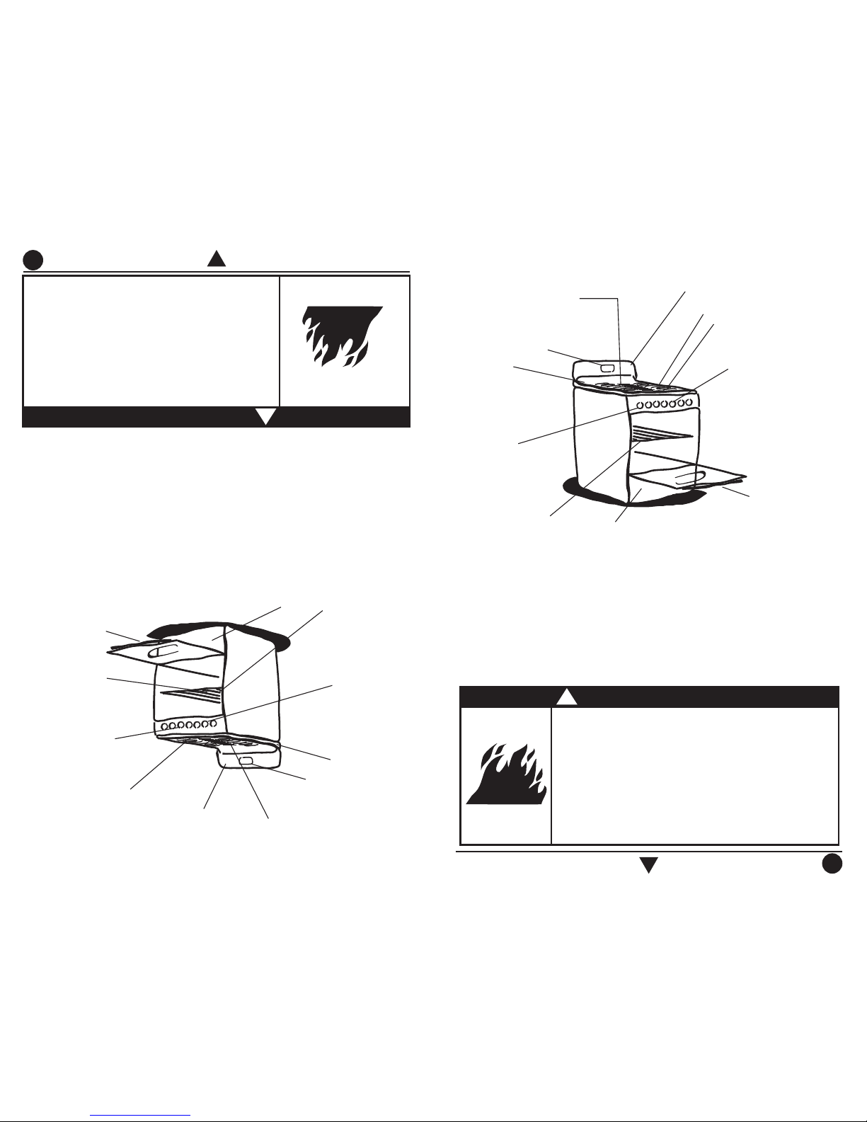
Parrillas Superiores
Parrilla de
Horno
Fire or Explosion Hazard
Do not allow children to use or play with the range;
keep children away while range is in use.
Keep the range surroundings free of flammable material,
gasoline and other vapors or flammable liquids.
Do not get too close to the flame produced by the
burners or wear loose clothing; your clothes may ignite
if contact by open flames.
Do not use your range to warm rooms, because this is
dangerous.
Failure to do so can result in death, fire or explosion.
WARNING
!
Termocontrol o
Termocontrol de 5 pasos
Termostato simple
(ver tabla pag. 2)
Asador
Perilla
Comal de sobreponer
Puerta de Horno
Thermocontrol or
Thermocontrol 5 steps
Simple Thermostat
see table page 2
Oven Grates
Broiler
Over Grate Griddle
Oven Door
Oven Rack
Top Burners
Knobs
Respaldo Superior
Cubierta
Cooktop
Backguard
Clock
Reloj
Page 4
4
4
Installation
61 cm
min.
Proper installation is your responsibility. A qualified
technician or Service technician must install this
range.
Remove all packing material and put the range
accessories in their places.
Select the best location in your kitchen for your
range. Protected from wind and
with enough space
to open the oven door.
Do not install cabinetry directly above the range.
If you will install an exhaust device, put it at 61 cm
minimum from the range cooktop.
If your range has a power cord it must be installed
near an electrical wall outlet.
Do not use extension cords or multiple outlets.
Instalación
La instalación apropiada es su responsabilidad.
Un técnico calificado o un técnico de Servicio debe
instalar esta estufa.
Retire los elementos de empaque y coloque los accesorios
de la estufa.
Seleccione la mejor ubicación para su estufa. No debe
quedar expuesta a corrientes de aire y debe tener espacio
suficiente para abrir la puerta del horno.
No instale gabinetes o
muebles de cocina encima de la
estufa.
Si instala campana extractora,
colóquela a 61 cm como
mínimo de la cubierta de la estufa.
Si su estufa cuenta con accesorios eléctricos colóquela
cerca de un tomacorriente de pared.
No use extensiones eléctricas o contactos múltiples.
61 cm
mínimo
CAMPANA EXTRACTO
RA
EXHAUST DEVICE
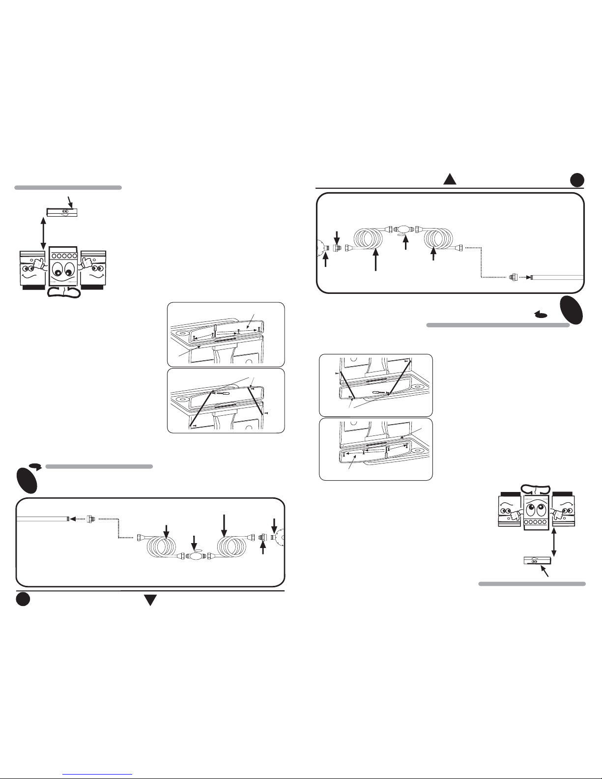
Conexión
CONEXIÓN DE LA ESTUFA A LA LÍNEA DE GAS
Para conectar su estufa, utilice el material especificado
en la figura de abajo.
1
Gas Supply Connection
GAS SUPPLY CONNECTION
To connect the range, use the material shown in the bottom figure.
1
NOTA: El m
aterial m
ostrado para instalacion no
viene con la estufa.
Tubo de Alim
entación
integrado a la estufa
Llave de paso
de 9,5 m
m (3/8")
Cople-Niple de 9,5 m
m (3/8"NPT)
a 9,5 m
m(3/8")cónica
Tubo de cobre con tuercas
cónicas de 9,5 m
m (3/8")
Tubo de cobre con tuercas
cónicas de 9,5 m
m (3/8") de
longitud necesaria para llegar
al gas
Cople-Niple de
9,5 mm (3/8"NPT)
Regulador
de gas
NOTA: Su estufa puede estar equipada de fábrica con:
1.- Tubo de Alim
entacion ó
2.- Válvula de Corte de G
as.
NOTE: The range could be equipped from
the factory with
one of the following accesories:
1.- Gas Inlet Tube Fitting or
2.- Shut Off Gas Valve.
3/8" shut off
valve
Gas Inlet Tube Fitting
integrated to the range
3/8" NPT to 3/8" brass pipe
fitting Hex. adapter
3/8" copper pipe
with 5/8" flared
type nut
Gas
regulator
3/8" copper pipe with
5/8" flared type nut.
Necessary
length to reach the
gas
3/8" brass pipe
fitting
Hex. adapter
NOTE: The m
aterial shown for installation
is not provided with the range.
How to Install the backguard in ranges
1.-Backguard parts are inside oven (Backguard,
rear supports, screws, washers, installation
instructions)
2.-Mount the backguard in place over the cooktop
(see figure 1)
3.-Use the screws and the washers to fix the
backguard to the range.
4.-Check that the backguard is property fixed.
5.- Assemble the rear supports as seen in figure 2.
Como instalar el respaldo superior
1.-Las partes del respaldo superior se encuentran
en el horno (respaldo, travesaños, tornillos,
roldanas, instrucciones de instalación)
2.-Coloque el respaldo sobre la cubierta (ver
figura 1).
3.-Utilizando los tornillos y las roldanas, atornille
el respaldo a la estufa.
4.-Verifique que el respaldo quede fijo.
5.- Coloque los travesaños como se muestra en
la figura 2.
Figura 1
RESPALDO
SUPERIO
R
BACKG
UARD
CUBIERTA
COOKTOP
TRAVESAÑO
S
Figura 2
REAR SUPPO
RTS
Figure 2
Figure 1
BACKG
UARD
COOKTOP
Page 5
5
5
Con el fin de facilitar el movimiento del
aparato, el instalador debe hacer una
espiral con el tubo flexible de cobre e
instalar una llave de paso en la línea
de suministro de gas. Esta llave debe
estar fuera de la estufa y accesible a
las personas que la usan.
Si la instalación no es nueva, limpie los
tubos de cobre, para evitar que se tapen
las espreas y/o pilotos.
IMPORTANTE
Esta estufa está preparada para
funcionar con gas L.P. de tanque
móvil o estacionario.
Para usarse con gas natural ( de
tubería) debe llamar a Whirlpool
Service para cambiar las espreas
y hacer los ajustes necesarios. El
número telefónico aparece en la
página 15. El técnico calificado
debe cerciorarse que la conexión
no tiene fugas y que la presión de
gas en la estufa es la que aparece
en las tablas.
NOTA: Para operar esta estufa con gas natural, se requiere
el juego de conversión de acuerdo con la siguiente tabla:
Este juego está disponible en Whirlpool Service
IMPORTANT
To make it easier to move the
appliance, the installer should loop the
3/8" copper tubing as shown in the
illustration.
If the installation is not new, you should
clean it in order to avoid the obstruction
of orifices and/or pilots.
This range is adjusted at the factory
for use with L.P. gas.
To use this range with natural gas,
you must replace the surface and
oven burner orifices, call Whirlpool
Service. The phone number
is shown in the page 15. The
technician must make sure that the
connections have no leaks and the
gas pressure in the range is the
same as shown in the charts.
NOTE: To operate this range with natural gas,
is required a kit according to the chart:
This kit is available at your nearest Whirlpool
Service.
2
Cheque con agua jabonosa
que no existan fugas.
2
Check with soap solution for leaks.
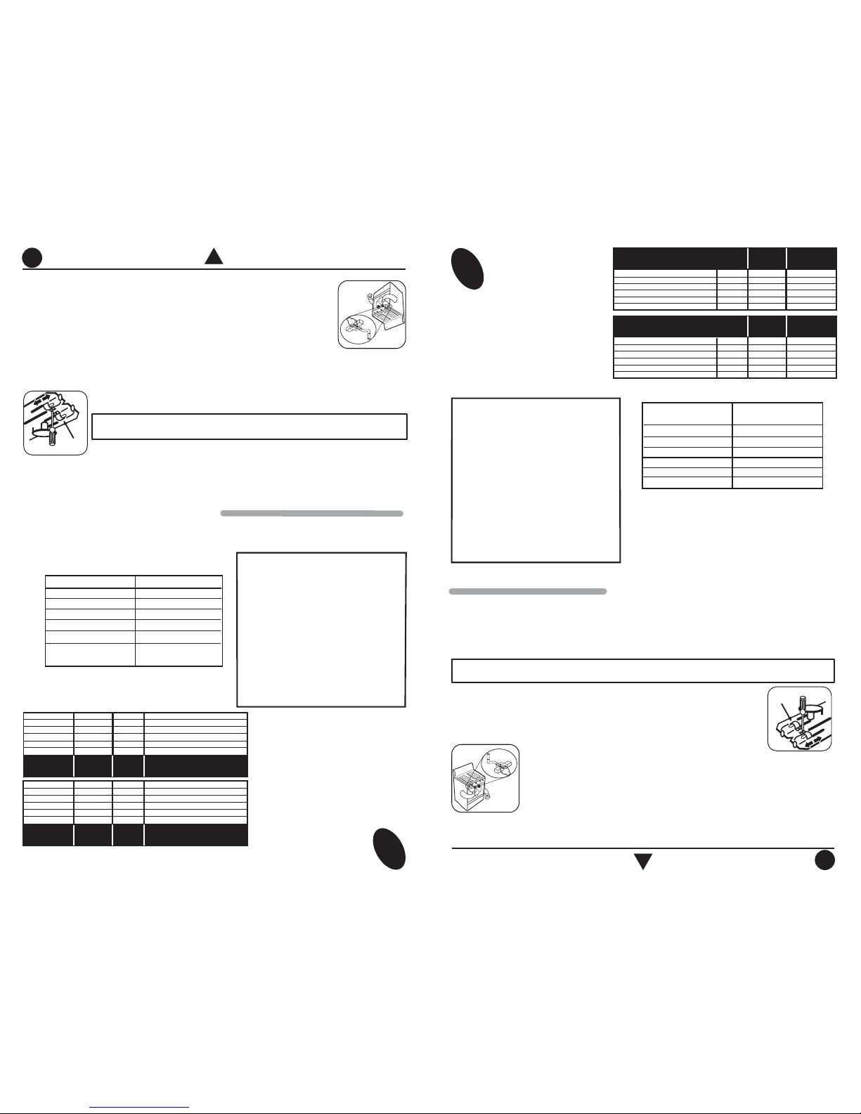
GAS LP PRESIÓN DE OPERACIÓN
2,75 kPa (28 cm Col. agua)
QUEMADOR
SUPERIOR STD. EST
AMPADO
SUPERIOR SUPER ESTAMPADO
SUPERIOR CENTRAL ESTAMPADO
SUPERIOR STD. ALUMINIO
HORNO
ESPREA
69
66
69
78
57
mm
0,741
0,838
0,741
0,78
1,092
kJ/h
6 800
7 500
6 800
7 000
13 600
DIAM.
ESPREA
CAPACIDAD
TERMICA
ESPREA
58
57
58
115
53
mm
1,06
1,09
1,06
1,15
1,511
kJ/h
6 800
7 500
6 800
7 000
13 600
DIAM.
ESPREA
CAPACIDAD
TERMICA
GAS NATURAL PRESIÓN DE OPERACIÓN
1,76 kPa (18 cm Col. agua)
QUEMADOR
SUPERIOR STD. ESTAMPADO
SUPERIOR SUPER ESTAMPADO
SUPERIOR CENTRAL ESTAMPADO
SUPERIOR STD. ALUMINIO
HORNO
Gas LP a
Modelo Gas Natural
NWF0600
NWF0601
NWF0602
NWF2900
NWF2901
NWF5900
W10132617
W10158283
W10217319
W10158283
W10217319
W10217319
Funcionamiento
How to Use Your Range
NUMBER
69
66
69
78
57
LP GAS OPERATING PRESSURE
11 in WATER COLUMN
(6,36 oz/squared inch)
BURNER
UPPER STD STAMPED
UPPER SUPER STAMPED
CENTRAL STAMPED
UPPER STD ALUM.
OVEN
INCHES
.029
.033
.029
.307
.043
BTU/h
6 500
7 100
6 500
6 700
13 000
ORIFICE
DIAMETER
THERMAL
CAPACITY
ORIFICE
NATURAL GAS OPERATING
PRESSURE 7 in WATER COLUMN
(4,04 oz/squared inch)
BURNER
UPPER STD STAMPED
UPPER SUPER STAMPED
CENTRAL STAMPED
UPPER STD ALUM.
OVEN
NUMBER
58
57
58
115
53
INCHES
.042
.043
.042
.045
.059
ORIFICE
DIAMETER
THERMAL
CAPACITY
ORIFICE
BTU/h
6 500
7 100
6 500
6 700
13 000
LP Gas a
Model Natural Gas
NWF0600
NWF0601
NWF0602
NWF2900
NWF2901
NWF5900
W10132617
W10158283
W10217319
W10158283
W10217319
W10217319
HOW TO ADJUST THE FLAMES
NOTE: Adjustment for top burners only apply for Models with Stamped
Burners (see page 2 ), for aluminium burners not apply
Air Regulator
AJUSTE DE FLAMAS
Las diferentes altitudes sobre el nivel del mar y las variaciones en el suministro de gas, hacen
necesario regular la entrada de aire primario a los quemadores para obtener una adecuada
mezcla de aire-gas y así obtener un buen funcionamiento en la estufa. Revise que las flamas
de los quemadores superiores y del horno sean estables y azuladas, de no ser así siga los
pasos para su ajuste.
Ajuste de quemadores superiores estampados
1.Retire las perillas.
2.Retire los tornillos que sujetan de abajo el frente de perillas y los tornillos
que sujetan el travesaño a los laterales en la parte posterior. (ver figura 1).
NOTA: El
ajuste de quemadores superiores solo aplica a los modelos con quemadores
estampados (ver Pág.2). Para los quemadores de aluminio no es necesario hacerlo.
REGULADOR
DE AIRE
3.Levante un poco el ensamble de la cubierta-frente perillas de la parte posterior,
jale hacia delante y levántelo tratando de evitar jalar los arnesesque vienen
fijos a la cubierta y al frente de perillas. Posiciónelo sobre los laterales de la
estufa (ver figura 2).
4.-Realice el ajuste dependiendo del tipo de quemador con el que cuente su
estufa.
a) Super quemador estampado y quemador estándar estampado
Afloje el tornillo del regulador de aire y abra o cierre la ventana (si la flama es amarilla, abra la
ventana; si la flama es inestable y separada del quemador, cierre la ventana).
Because of different altitudes above sea level and variations in the supply of gas, you may
need to adjust the main air intake to the oven burner. This will result in a better air-gas
mixture and thus.
Check oven burner and Top Burners for proper flame, flame must be stead and blue if not,
follow instructions for flame adjustment.
Top Burners Adjustment for Stamped Burners
1.- Remove knobs.
2.- Unscrew the screw below the manifold panel and the screws that support post to the
laterals at rear side (see fig. 1) and remove it.
3.-Unscrew the screw below, back and the top the cooktop and remove it(See fig. 2)
4.-Carry the adjustment of the burner according the kind of burner your range have.
a) S
tamped Standard Burner and Super Stamped Burner
Adjust air by loosing air shutter screw and turn air shutter to open or close
opening
(if flame is yellow, open burner opening; if flame is blowing, close
opening)
b) Five Burner
Displace the regulator in order to open or close opening (if flame is
yellow
, open burner opening; if flame is blowing close opening.
Page 6

66
6
HOW TO TURN ON THE BURNERS MANUALLY
To turn on the surface burners manually:
1.- Light a match and place it close the burner while you
push and turn the knob 1/4 of the way until the position
of maximum flame the burner will light immediatly.
Para encender los quemadores superiores con
encendido electrónico en la perilla:
1.- Algunos modelos (ver pág. 2) cuentan con encendido
electrónico en la perilla. Para operarlo gire la perilla
del quemador que desea encender hasta la posición
de encendido (ver figura).
2.- Para que la bujía de encendido deje de producir
chispas, gire la perilla hasta la posición de flama
máxima.
Perilla en posición de encendido.
ENCENDIDO ELECTRÓNICO DE QUEMADORES SUPERIORES
Para encender los quemadores superiores con encendido electrónico
independiente:
1.- Algunos modelos (ver pág. 2) cuentan con
encendido electrónico independiente. Para
operarlo oprima el botón que se localiza en el
lado izquierdo del frente de perillas y al mismo
tiempo presione y gire a la posición de flama
máxima como se indica en la figura, la perilla del
quemador que desea encender.
NOTA: En caso de no contar con electricidad, su estufa puede ser encendida manualmente.
TOP BURNERS WITH ELECTRONIC IGNITION
To turn on the surface burners with electronic
ignition in the knob:
1.- Some models (see page 2) have electronic ignition
integrated in knobs, to operate push and turn the
desired knob to the ignition position. (See illustration).
2.- To stop the sparks turn the knob to the
maximum flame position.
To turn on the surface burners with independent
electronic ignition:
Some models (see page 2) have independent
electronic ignition, to operate it push the button
located on the left side of the manifold panel
while you push and turn the desired knob.
Release the ignition button when the burner
lights.
NOTE: In the case on power cut, your range can be ignited manually.
APAGADO
FLAMA
MÍNIMA
FLAMA
MÁXIMA
Knob on the mark of ignition.
OFF
MINIMUM
FLAME
MAXIMUM
FLAME
Perilla en posición de encendido.
APAGADO
FLAMA
MÍNIMA
FLAMA
MÁXIMA
BOTÓN DE ENC.
ELECTRÓNICO
Knob in ignition position.
OFF
MINIMUM
FLAME
MAXIMUM
FLAME
ELECTRONIC
IGNITION
BUTTON
5.Coloque nuevamente en su lugar la charola de horno, el ensamble de la cubierta con el
frente perillas y todos los tornillos asegurándose de que el ensamble quede fijo. Verifique
que los cables que van de la cubierta al módulo no se hayan salido de su posición.
6.Coloque las perillas (ver pág. 11).
tornillos travesaño posterior
a laterales
tornillos frente de perillas
Figura 1
Figura 2
módulo
Para encender los quemadores superiores:
Acerque un cerillo encendido al quemador y al mismo
tiempo presione y gire 1/4 de vuelta hasta la posicion de
flama máxima la perilla del quemador correspondiente.
ENCENDIDO MANUAL DE QUEMADORES SUPERIORES
b) Quemador alargado estampado
Desplace el regulador para abrir o cerrar la ventana (si la flama
es amarilla, abra la ventana; si la flama es inestable y separada
del quemador, cierre la ventana).
post screws rear to
laterals
manifold panel screws
Figure 1
Figure 2
module
5.- Put the cooktop, baking tray and the manifold panel in its place, verify adequate
assembly of cooktop with manifold panel, screws and all is assembly. Verify that cables
from module to cooktop assembled and Verify that the flames are blue and stable, if
the flame aren´t blue, repeat all the steps until obtain flames blue.
6. Put the knobs. (See pag. 11)
Perilla en posición de encendido.
APAGADO
FLAMA
MÍNIMA
FLAMA
MÁXIMA
Knob on the mark of ignition.
OFF
FLAMA
MÍNIMA
FLAMA
MÁXIMA
Page 7

7
7
Para encender el horno con termocontrol de
encendido manual:
1.- Encienda un cerillo y colóquelo cerca del
agujero de la charola del horno. Al mismo
tiempo presione y gire 1/4 de vuelta hasta la
posicion de flama máxima la perilla del horno.
2.- Verifique que el quemador del horno se haya
encendido.
HORNO CON TERMOCONTROL
APAGADO
FLAMA
MÍNIMA
FLAMA
MÁXIMA
OVEN WITH THERMOCONTROL
How to light the oven burner with thermocontrol, manually:
1.- Open the oven door, light a match and place
the flame at the igniter hole in the front of the
oven tray. While you push in and turn the oven
knob 1/4 of the way, until the position
of maximum flame the burner will light
immediately.
2.- Verify that the oven burner has been ignited.
OFF
FLAMA
MÍNIMA
FLAMA
MÁXIMA
Para encender el horno con termocontrol de
5 pasos y encendido manual:
1.- Encienda un cerillo y colóquelo cerca del
agujero de la charola del horno. Al mismo
tiempo presione y gire la perilla hasta la
posicion No. 5 indicada en el panel de control.
2.- Verifique que el quemador del horno se haya
encendido.
APAGADO
HORNO CON TERMOCONTROL DE 5 PASOS
How to light the oven burner with 5 steps thermocontrol,
manually:
1.- Open the oven door, light a match and place
the flame at the igniter hole in the front of the
oven tray. While you push in and turn the oven
knob until the 5th position indicated on the
control panel.
2.- Verify that the oven burner has been ignited.
OFF
OVEN WITH 5 STEPS THERMOCONTROL
Knob position to use the broiler.
Some models (see page 2) have broiler in the bottom of
the range.
To use the broiler you should turn on the oven as indicated
on page 5, the knob must be as shown in the figure (MAX).
The oven should be empty.
BROILER
Algunos modelos (ver pág. 2) cuentan con asador en la
parte inferior de la estufa.
Para que el asador funcione debe encender el horno
como se indicó anteriormente. La perilla debe estar en
la posición que indica la figura (MAX). El horno debe
estar vacío.
ASADOR
Para encender el horno manualmente.
1.- Encienda un cerillo y colóquelo cerca de la charola
del horno. Al mismo tiempo gi
re y presione la perilla del
horno.
2.-Verifique visualmente a través del orificio de la charola
que el quemador del horno se haya encendido.
HORNO CON TERMOSTATO SIMPLE
APAGADO
MAX
HORNO
OVEN
140
160
180
200
225
C
250
How to light the oven burner with simple
thermostat, manually
1.- Open the oven door, light a match nad place the flame
at igniter hole in the front of the oven tray. While you push
in and turn the oven knob.
2.-Verify that the oven burner has been ignited.
OVEN WITH SIMPLE THERMOSTAT
OFF
MAX
HORNO
OVEN
140
160
180
200
225
C
250
5
2
3
1
4
stm01845
Rev A
HORNO
OVEN
5
2
3
1
4
stm01845
Rev A
HORNO
OVEN
Posición de la perilla para usar el
asador.
APAGADO
MAX
HORNO
OVEN
MAX
HORNO
OVEN
Page 8

8
8
Para retirarla de la estufa:
1.- Jale la parrilla hasta el tope.
2.- Levante la parrilla de la parte frontal.
3.- Jale nuevamente para liberarla.
Para instalarla en la estufa:
1.- Empuje la parrilla hasta el tope.
2.- Levante la parrilla de la parte
frontal.
3.- Empújela nuevamente para que
llegue hasta el fondo del horno.
PARRILLA DEL HORNO
El horno tiene 3 diferentes soportes para la parrilla, la cual tiene un tope que evita que
se salga completamente del horno. Para cambiar la posición de la parrilla siga los
siguientes pasos:
OVEN RACK
The oven has 3 different supports for the oven rack, this has a stop to avoid droping from
the oven, to change the rack position follow the steps:
To remove the oven rack:
1.- Pull the oven rack until it
stops.
2.- Lift the front part.
3.- Pull it again until it is
released.
To install the oven rack:
1.- Push the oven rack until it
stops.
2.- Lift the front part.
3.- Push it again until it stops.
Asador con 3 niveles:
Seleccione la posición donde desea utilizar la charola.
- Posición alta para asar.
- Posición media para dorar.
- Posición baja para gratinar.
Asador con un solo nivel:
Coloque la charola en las 2 guías como se
muestra en las siguientes figuras.
GUÍA
ORIFICIO
CHAROLA
ASADOR
GUÍA
CHAROLA
ASADOR
COMAL
No use materiales abrasivos, fibras de plástico o metal para limpiarlo; use agua
jabonosa y una esponja.
Algunos modelos (ver Pág. 2) cuentan con comal.
Broiler with only one level:
Put the broiler tray in the guides as
shown in following figures.
GUIDE
HOLD
BROILER
PAN
GUIDES
BROILER
PAN
PORCELAINIZED GRIDDLE
Do not use abrasive,plastic or metal material to clean it, use soap water and a sponge.
Some models (see page 2) have griddle.
Broiler with 3 levels:
Choose the position to use the broiler tary:
- Top position for broiling.
- Medium position for browning.
- Low position for melting.
PARRILLAS AUTODESLIZABLES
La parrilla puede ubicarse en el horno en cinco posiciones diferentes. Para su
comodidad la parrilla es autodeslizable.
Cómo retirar la parrilla del Horno
1.- Levante la parrilla A de la parte posterior
y después del frente para poder retirarla.
Cómo colocar la parrilla del horno:
1.- Inserte la varilla en los soportes.
A
Algunos modelos (ver Pág. 2) cuentan con parrilla autodeslizables.
RETRACTABLE OVEN RACK
The oven rack can be placed in 5 different positions. For your convenience this rack is
retractable
How to remove the oven rack
1.- Lift the oven rack A from the rear
an then from the front in order to
remove it.
How to Install the oven rack:
1.- Insert the rod wire in the supports.
A
Some models (see page 2) haveretractable oven rack
NOTA: Use el comal con FLAMA BAJA.
NOTE: Use the Griddle with LOW FLAME.
Page 9

9
9
4.- Quite las varillas de los soportes.
2.- Los soportes de la parrilla
también se pueden quitar, para
retirarlos suelte el extremo de la
varilla B que está enganchada en
la puerta.
3.- Deslice el soporte hacia afuera pasando
las ruedas de metal por la abertura del
carril lateral C.
2.- Instale los soportes pasando las
ruedas de metal por la abertura del
carril central y empuje hasta el fondo.
3.- Asegure el extremo de la varilla
en la base D que se encuentra en la
puerta.
4.- Ponga la parrilla en el nivel
deseado colocándola primero en la
parte posterior de los soportes y
después en la parte frontal, como se
muestra en las siguientes figuras .
B
C
D
4.- Take out the rod wire of the
supports.
2.- The supports of the oven rack can
be removed also, to remove them
take off the edge of the wire B that is
hooked in the oven door.
3.- Slide the support out with the
metal rollers through the aperture of
the side rail C.
2.- Install the supports passing the
metal rollers through the aperture of
the central rail and then push to the
rear.
3.- Insert the extreme of the wire in
the base D that is located in the oven
door.
4.- Put the oven rack in the desired
level, placing first the rear supports
and the front supports after. Make
sure it is fixed firmly.
B
C
D
NOTA: El cable tomacorriente debe
conectarse a una toma de corriente con un
voltaje de 127 V ± 10%.
Cerciórese de que la instalación esté
apropiadamente aterrizada.
Para reemplazar el foco del horno:
1.- Desconecte el cable tomacorriente de
la estufa.
2.- Retire el foco y reemplácelo con un
foco nuevo de 40 watts especial para
aparatos domésticos.
3.- Conecte la estufa nuevamente.
LUZ DE HORNO
Algunos modelos (ver Pág. 2), cuentan con luz en el horno. La iluminación es importante
para revisar el horneado sin abrir la puerta.
Algunos modelos tienen el interruptor en el lado izquierdo del frente de perillas. Otros
modelos lo tienen integrado frente a la puerta del horno y se acciona automáticamente
al abrirla.
NOTE: Connect the range in a wall outlet with a voltage of
127 V ± 10%. Be sure the installation is properly grounded.
OVEN LIGHT
Some models (see page 2) have an oven light.
Some models have the light switch located on the left side of
the manifold panel. Other models have an integrated light
switch in front of the oven door and is activated automatically
when the door is opened.
How to replace the oven bulb:
1.- Disconnect the power cord.
2.- Remove the bulb and replace with a new 40 watts special
appliance bulb.
3.- Connect the power cord again.
Page 10

10
10
Algunos modelos (ver pág. 2 ) cuentan con perillas Doble Seguridad, las cuales brindan
seguridad adicional para su familia a través de un candado individual.
Las perillas Doble Seguridad funcionan a través de una palanca impide girar la perilla para
encender el quemador.
Active el candado individual de las perillas cuando no utilice su estufa.
PERILLA DOBLE SEGURIDAD
La perilla se puede girar si la palanca se coloca en la posición
del candado abierto
. Si la palanca se coloca en la posición
del candado cerrado
, la perilla no podrá girarse.
Forma correcta de operar las perillas Doble
Seguridad:
PERILLA DOBLE SEGURIDAD
Perilla con Candado
NO GIRA
Perilla sin Candado
SÍ GIRA
Una vez que ha girado la perilla para encender el quemador, la palanca debe
quedar en posición de candado abierto, como se muestra en la figura.
IMPORTANTE
El colocar la palanca en posición de candado cerrado, cuando el quemador está encendido,
podría dañar o dificultar la operación de la perilla Doble Seguridad.
DOBLE SEGURIDAD KNOB
IMPORTANT
Some models (see page 2) have Doble Seguridad
knobs,these are knobs with a lever that activate an
extra safety mechanism for children. If you do not
have children at home is not necessary to activate
the lever each time you turn off the burners.
The knob can be turned if the lever indicates the
unlock position . If the lever indicates the lock
position, the knob can not be turned.
Once you have turned on the
burner, the lever must be
maintained on unlocked position,
as shown in the figure.
Putting the lever on lock position when the burner
is turned on, may damage or difficulty the operation
of Doble Seguridad.
DOBLE SEGURIDAD KNOB
Locked knob
KNOB CAN NOT TURN
Unlocked knob
KNOB CAN TURN
To program the timer:
1.- Push the button (a point at right side will glow).
2.- Push the and buttons to fix the desired time, (the maximum timer
time is 1 hour 59 minutes).
IMPORTANT: Do not change the clock mode. When the timer finishes, a bell will
ring. Pushing the button while the timer is running will stop and clear the
timer.
NOTE: The clock is adjusted at the factory to work with a frecuency of 60 Hz, if in
your comunity the electrical supply is at 50 Hz, move the small lever located on the
To adjust the digital clock:
1.- Push the button.
2.- Push the button until the hour is adjusted.
3.- Push the button until the minutes are adjusted.
DIGITAL CLOCK / TIMER
Some models (see page 2) include digital clock / timer.
Para programar el timer:
1.- Oprima la tecla (se encenderá un punto del lado derecho).
2.- Oprima las teclas ó hasta fijar el tiempo en que desee que suene el timer.
IMPORTANTE: No cambie a reloj, deje el tiempo programado. Cuando el tiempo se
complete sonará el timer.
3.- Para desactivar el TIMER oprima la tecla y aparecerá la hora normal.
NOTA: El TIMER marca un tiempo máximo de 1:59 horas.
NOTA: El reloj viene ajustado de fábrica para trabajar a la frecuencia de 60 Hz, si en
su localidad la corriente eléctrica es de 50 Hz, mueva la palanquita localizada en la
parte posterior del reloj hacia la izquierda.
Como funciona su reloj digital:
1.- Oprima la tecla donde aparece .
2.- Oprima las teclas o , hasta fijar la hora correcta. En P.M. se enciende un
punto en el lado izquierdo del reloj.
Algunos modelos (ver Pág. 2) cuentan con reloj / timer digital.
RELOJ / TIMER DIGITAL
Page 11

11
11
Para todos los tipos de perillas, excepto la del horno (H), vendrán
marcadas en la parte posterior con los números a los que se hace
referencia en la siguiente tabla:
Central (C)
Lateral (L1)
Lateral (L2)
Si usted retira las perillas para facilitar la limpieza de su estufa,
posteriormente deberá colocarlas de acuerdo al siguiente diagrama:
1.- Coloque la válvula en posición de Apagado.
2.- La perilla debe estar en posición vertical, con el indicador hacia arriba
y la palanquita apuntando hacia la izquierda (ver la figura de la
derecha).
3.- Inserte la perilla en la válvula asegurándose que el pernito de atrás
de la perilla entre en el agujero del frente de perillas. Empuje
firmemente la perilla hasta que tope con el frente de perillas.
En caso de retirar las perillas para limpieza, colóquelas de acuerdo a las
siguientes instrucciones:
Para ensamblar las perillas Doble Seguridad:
1.- Coloque el resorte sobre la base de la perilla.
2.- Coloque la perilla encima del resorte e inserte en la
base. El indicador de la perilla debe apuntar hacia
arriba mientras que la palanca de la base apunta
hacia abajo.
BASE DE LA PERILLA
RESORTE
PERILLA
L2 L2L1CC HL1
How to install the knobs if you remove them for cleaning:
1.- The valve should be in off position.
2.- The knob should be in vertical position, the indicator
up and the small lever to the left side (see the illustration).
3.- Insert the knob in the valve, be sure that the small pin behind
the knob is aligned to the hole on the manifold panel. Push the
knob until the face of the manifold panel.
To assembly the knobs:
1.- Put the spring on the knob base.
2.- Put the knob on the spring. The indicator must
be upside while the lever of the base must be
pointed down.
3.- Insert the metallic ring on the knob shaft.
METALLIC RING
KNOB BASE
SPRING
KNOB
For all kind of knobs, except the oven knob (H), all of them will come
marked on the back of the knob with the following numbers wich are
refered in the next table:
Central (C)
Lateral (L1)
Lateral (L2)
If you remove the knobs for clean your range, you should place it like
next diagram:
L2 L2L1CC HL1
Single knob or
body knob
knob with
skirt
super safety
knob
21.5
19
16
L2
L1
C
19
16
13
19
16
13
Perilla sencilla
o solo cuerpo
Perilla con
faldon
Perilla doble
seguridad
21.5
19
16
L2
L1
C
19
16
13
19
16
13
NWF0600W NWF0601Q
NWF2901Q
NWF5900Q
NWF2900Q
NWF0600W NWF0601Q
NWF2901Q
NWF5900Q
NWF2900Q
L2 L2L1HL1 C
L2 L2L1HL1 C
Page 12

12
12
Para su seguridad:
Si huele a gas
Abra las ventanas.
No toque interruptores
eléctricos.
Apague todas las
flamas cerrando la
válvula general de
paso.
Llame inmediatamente
a la central de fugas o
a su proveedor de gas.
No seguir estas
instrucciones puede
ocasionar riesgo de
fuego o explosión.
ADVERTENCIA
!
Para su seguridad:
No almacene gasolina u
otros fluidos flamables
en la cercanía de su
aparato.
Asegúrese que los
muebles cercanos a su
estufa, así como el
muro y piso soporten
una temperatura de
180° C, para que no
sufran deformaciones.
No obstruya las
ranuras de la charola
del horno.
No seguir estas
instrucciones puede
ocasionar riesgo de
fuego o explosión o la
muerte.
ADVERTENCIA
!
Limpieza
Desconecte el cable toma corriente de la estufa, si su estufa cuenta con este. Es necesaria
la limpieza periódica de la estufa, use agua, jabón y un trapo húmedo, no use fibra metálica,
porque se ralla el esmalte. Limpie regularmente el hueco entre la cubierta superior y el
frente de perillas.
Su estufa cuenta con el Sistema de Autolimpieza en el horno (acabado rugoso), no es
necesario que limpie las paredes, ya que con cada horneado se van quemando los residuos
de alimentos que se van salpicando.
No utilice sosa cáustica o productos de limpieza que la contengan para limpiar la estufa.
De no seguir esta instrucción se ocasionarán daños perm
anentes en las superficies donde se aplique.
IMPORTANTE
Como retirar la charola del horno:
1.- Gire los dos sujetadores
frontales
2.- Levante la charola del frente
3.- Despues levantela de la parte trasera y retirela.
For your safety
IF YOU SMELL GAS:
Open the windows.
Do not activate any
light switch.
Close the gas line
supply and the
connection shut off
valve.
I
mmediately call your
authorized repair
service or your gas
supplier.
Failure to follow the
above precautions
may result in fire or
explosion.
WARNING
!
For your safety
Do not store gasoline
or other flamable
liquids near to your
range.
Make sure that the
furniture near to your
range, as well as the
wall and the floor must
support a temperature
of 180°C to avoid any
deformation.
Do not obstruct the
side grooves in the
oven tray.
Failure to follow the
above precautions
may result in death,
fire or explosion.
WARNING
!
Cleaning and Maintenance
Unplug range from current.Regularly clean grates, burners, cooktop and the oven tray, use
water, soap and a damp cloth, avoid using abrasive or sharp objects. Periodically clean
the gap between the cooktop and the manifold panel.
Your range has the
Continuous Cleaning System
in the oven, it is not necessary to clean
the walls of the oven, the spills will burn each time you bake.
Do not use caustic soda or cleaning agents which contain it to clean the range.
Failure on following the above, will permanently damage the surfaces where it is applied.
IMPORTANT
How to remove the oven tray:
1.- Turn front clips.
2.- Lift front of tray.
3.- Lift rear of tray and remove it.
Page 13

13
13
Foco de Horno 40 W.
Diagrama Eléctrico Estufa con Luz en el Horno y
Encendido Electrónico con Interruptor Independiente.
Módulo de Encendido
4, 6 u 8 salidas.
Interruptor Luz de Horno e Interruptor Módulo de
Encendido Integrados
N
L1
Interruptor Luz de Horno e Interruptor Módulo de
Encendido Integrados
Integrated Oven Light Switch & Electronic Ignition
Switch
Foco de Horno 40 W
Oven Bulb 40 W
Módulo de Encendido
4, 6 u 8 salidas
4, 6 or 8 outlets Ignition
Module
Reloj
Clock
Diagrama Eléctrico Estufa con Luz en el Horno y
Encendido Electrónico con Interruptor Independiente y Reloj.
N
L1
Electrical Diagram Range with Oven Light and
Electronic Ignition with Independent Switch.
Oven Bulb 40 W
Ignition Module.
Integrated Oven Light Switch & Electronic Ignition
Switch
N
L1
Interruptor Luz de Horno e Interruptor Módulo de
Encendido Integrados
Integrated Oven Light Switch & Electronic Ignition
Switch
Foco de Horno 40 W
Oven Bulb 40 W
Módulo de Encendido
4, 6 u 8 salidas
4, 6 or 8 outlets Ignition
Module
Reloj
Clock
Electrical Diagram Range with Oven Light and
Electronic Ignition with Independent Switch and Clock.
N
L1
ELECTRICAL DIAGRAMS
DIAGRAMAS ELÉCTRICOS
Page 14

14
14
Este documento deberá ser presentado para cualquier
trámite relacionado con la garantía de productos
adquiridos dentro de la República Mexicana, si usted
compró su producto en otro país, acuda a la casa
comercial/ distribuidor donde fué adquirido.
EL COMPRADOR DEBERÁ MANTENER ESTE
DOCUMENTO EN SU PODER Y EN UN LUGAR
SEGURO.
El consumidor podrá solicitar que se haga efectiva la
garantía que ampara esta póliza, ante la casa comercial
donde se adquirió el producto. En caso de extravío de
la póliza mencionada, el proveedor expedirá una nueva
póliza de garantía, previa presentación de la nota de
compra o factura respectiva.
WHIRLPOOL SERVICE
Dentro de la República Mexicana
Utilice sin cargo para usted el Centro
Nacional de Llamadas
Teléfono 01-800-83-004-00
FORMATO DE IDENTIFICACIÓN
N
OMBRE DEL COMPRADOR ______________________________________
DOMICILIO_________________________ TEL. ______________________
NOMBRE DEL DISTRIBUIDOR _____________________________________
DOMICILIO __________________________ TEL. ______________________
PRODUCTO______________ MARCA_________ MODELO_____________
NUM. DE SERIE ________________FECHA DE ENTREGA_______________
FIRMA DEL DISTRIBUIDOR Y SELLO REPRESENTANTE AUTORIZADO
(Señale con precisión calle, número exterior o interior;
colonia, ciudad, estado y C.P.)
NOTA IMPORTANTE
WHIRLPOOL MEXICO, S.A. DE C.V.
Antigua Carretera a Roma km 9, Col. Milagro, Apodaca, N.L., México, C.P. 66600, Tel. (81)83-29-21-00,
en los términos de esta póliza, garantiza al comprador de la estufa identific
ada en la presente póliza,
exclusivamente lo siguiente:
CONCEPTOS CUBIERTOS POR LA GARANTÍA:
Defectos de fabricación que impidan total o parcialmente el correcto funcionamiento de la estufa, que
se presenten dentro del término de vigencia de esta garantía.
Reparación, cambio de piezas y componentes.
Mano de obra y gastos de transportación derivados del cumplimiento de la garantía, dentro de nuestra
red de servicio.
Los puntos anteriores se harán sin costo alguno para el Consumidor.
CONCEPTOS NO CUBIERTOS POR LA GARANTÍA:
- Cuando el producto ha sido utilizado en condiciones distintas a las normales (la estufa no es para uso
comercial o industrial).
- Cuando el producto no ha sido operado de acuerdo con el instructivo de instalación y uso de la estufa.
- Cuando el producto ha sido alterado o reparado por personas o establecimientos no autorizados por
Whirlpool Service.
PROCEDIMIENTO PARA HACER EFECTIVA LA GARANTÍA:
Al considerar el comprador final que ha ocurrido algún evento amparado por esta póliza, deberá
ponerse en contacto con Whirlpool Service a nuestro Centro Nacional de Llamadas, desde
Monterrey N.L y su área conurbada al (81) 83-29-2100 y desde el interior de la República
Mexicana al 01-800-8-300-400; donde un asesor de servicio especializado lo atenderá. Nuestras
instalaciones están ubicadas en Carretera Miguel Alemán km. 16 Col. El Milagro C.P 66600.
Apodaca, N.L. En donde también podrá encontrar accesorios y partes originales. Para mayor
información de nuestros servicios, visite www.whirlpoolservice.com.mx.
Esta garantía quedará sin efecto cuando personas o establecimientos no autorizados intervengan en
la reparación o reemplazo de componentes de fabricación.
TÉRMINO:
Esta garantía tiene una vigencia de UN AÑO a partir de la fecha en que el consumidor reciba de
conformidad la estufa.
PÓLIZA DE GARANTÍA
This document must be shown in any
transaction related with this warranty for
products acquired in the Mexican Republic.
If you bought your range out of the Mexican
Republic, ask your authorized dealer to
make valid your warranty.
THE CONSUMER CAN REQUEST THE
WARRANTY COVERED BY THIS POLICY
FROM THE DEALER WHERE THE
PRODUCT WAS PURCHASED.
In case of loss of policy, the dealer will issue
a new one, with the proper bill of sale or
invoice.
WHIRLPOOL SERVICE
Call free in Mexico
Use without charge the Nationwide
Call Center
Phone number 01-800-83-004-00
IDENTIFICATION FORMAT
CONSUMER NAME
_____________________________________________
ADDRESS________________________ PHONE ______________________
DEALER NAME__________________________________________________
ADDRESS ________________________ PHONE ______________________
PRODUCT___________TRADEMARK______________ MODEL __________
SERIAL NUMBER ________________DELIVERY DATE__________________
DEALER SIGNATURE AND STAMP AUTHORIZED REPRESENTATIVE
(Indicate precise steet, col. state and zip code).
IMPORTANT NOTE
WARRANTY
WHIRLPOOL MEXICO, S.A. DE C.V.
Antigua Carretera a Roma km 9, Col. Milagro, Apodaca, N.L., Mexico, C.P. 66600,
phone (81)83-29-21-00, in the terms of this policy, we warranty to the buyer and the
consumer of this range identified in this following policy:
COVERED CONCEPTS:
Manufacturing defects that hinder total or partially the correct performance of the appliance.
Repair, change of pieces and components.
Handwork and transportation expenses derived from the fulfillment of the warranty, within
our service net. The previous points will be made without any cost for the consumer.
NOT COVERED CONCEPTS:
- When the range is used in other than normal, single family household use.
- When the range is not used according to the use and care guide attached.
- When the range has been repaired by unauthorized service.
PROCEDURE TO MAKE EFFECTIVE THE WARRANTY:
When the final customer considers one of the events protected by this contract has happened,
he/she will have to make contact with Whirlpool Service through our Call Center, in Monterrey, N.L
and its surrounding area to (81) 83-29-2100; or from the interior of the Mexican Republic to 01-
800-8-300-400:where a specialized service agent will take care of the matter. Our facilities are
located in Miguel Alemán Highway km 16 Col. El Milagro C.P 66600. Apodaca, N.L. where Whirlpool
original parts and accessories can also be found. For additional information of our services, visit
www.whirlpool-service.com.mx.
TERMS:
This warranty covers ONE YEAR beginning the day the buyer or consumer receives the
range to his satisfaction.
Page 15

15
15
Page 16

16
16
NOTAS:
NOTES:
 Loading...