

Page 1

SERVICE
Model MT 244/1/BLACK
Version 8538 244 99481 Page
Whirlpool Europe
Customer Services
MT 244/1/BLACK
Service Manual
Microwave oven
MT 244/1/BLACK
Introduction safety 2
Technical data 3
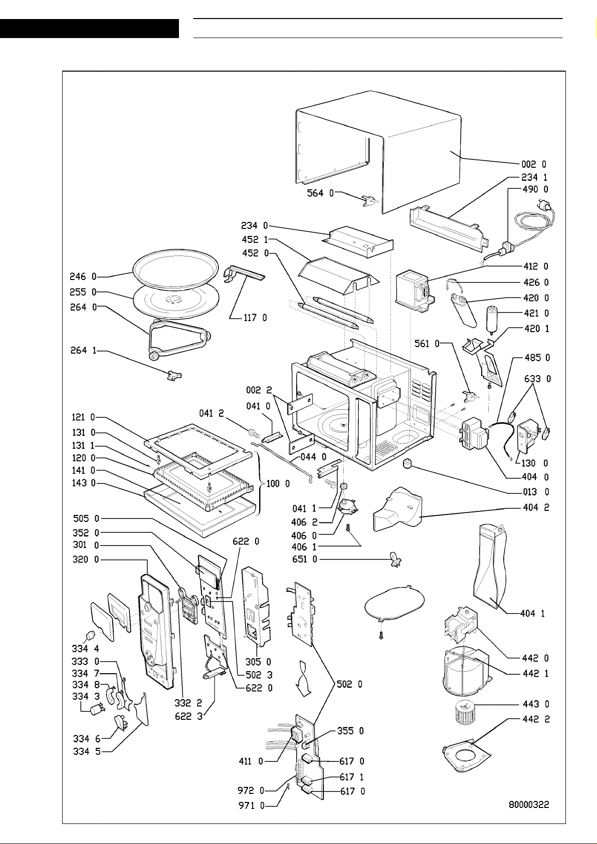
Spare part list 4
Exploded view 5
Wiring diagram 6
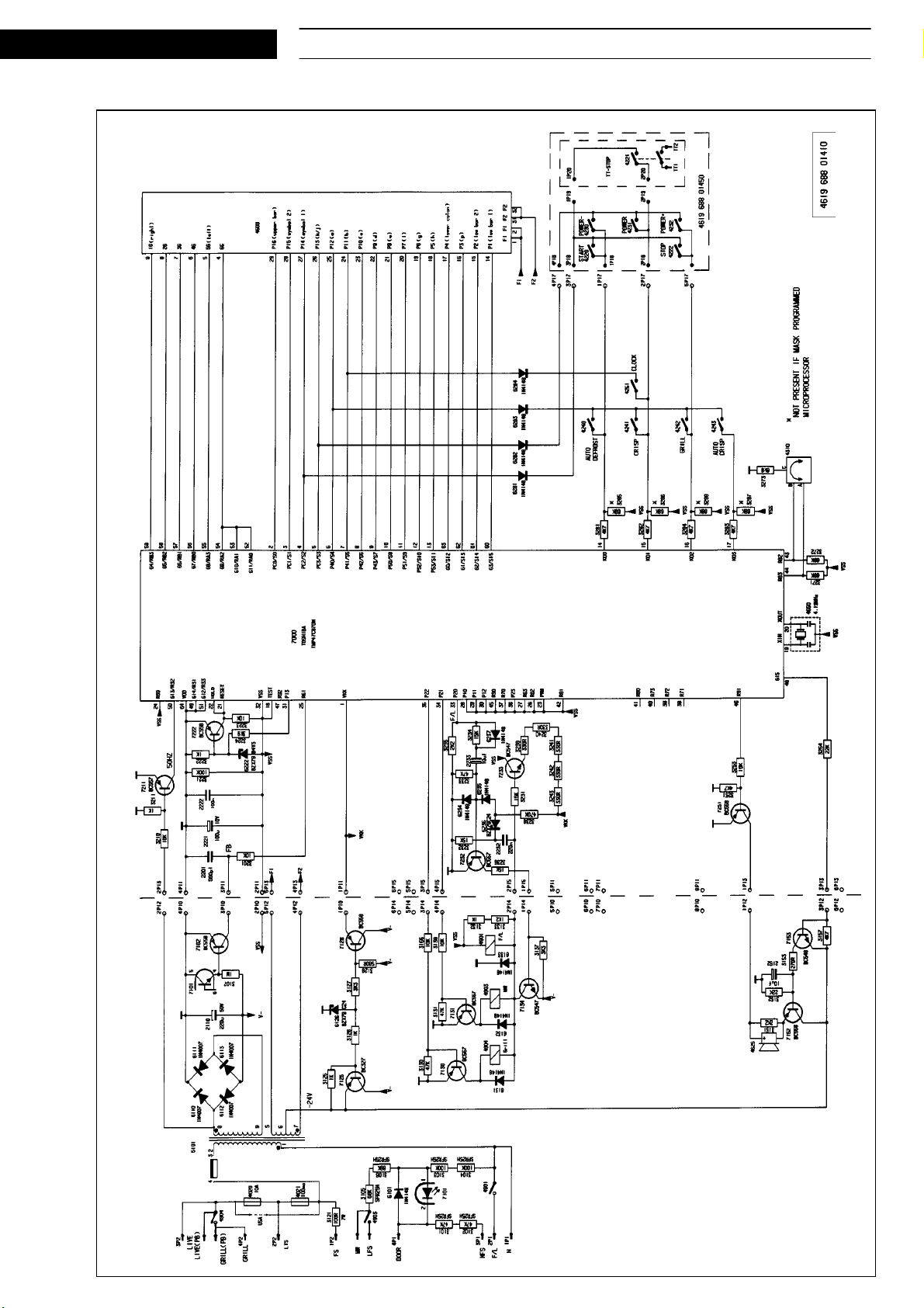
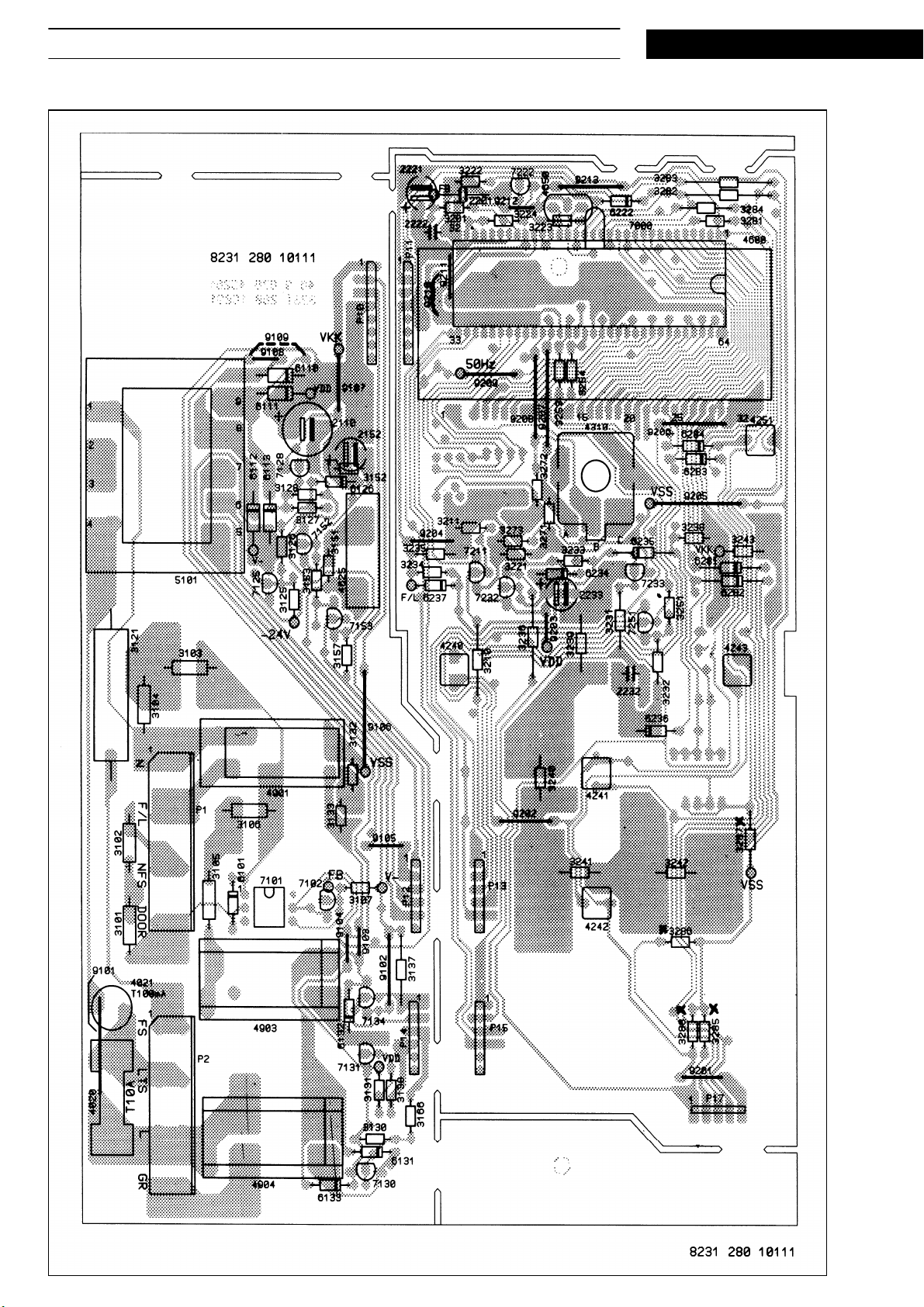
Program diagram 7 - 8
This documentation is only intended for qualified technicians who are aware of the respective safety regulations.
Date: 07.03.2000 Subject to modification
Document-No.: 4812 714 13304
Page 2

07.03.2000 / Page 2 MT 244/1/BLACK Whirlpool Europe
Doc. No: 4812 714 13304 8538 244 99481 Customer Service
SERVICE
Introduction safety
INTRODUCTION
Before leaving the factory each oven is carefully checked.
It must, however, be installed and used correctly.
Despite all the steps taken to make the oven safe, the safety is dependent on the correct installation and the fact
the user understands how to use and maintain the oven.
The information in this section should be used as a reminder that the oven is safe and that anyone who uses it must
first read the instructions for use in order to be able to use the oven correctly and obtain best results.
SAFETY
To avoid injury to yourself and damage to the appliance always work to the following rules when servicing an oven.
Always disconnect the plug from the mains before starting work.
If there is no plug switch off the electric supply at the control box.
When you have finished servicing an oven before you reconnect it to the mains, make sure that:
- all the internal connections are correct
- the wires are insulated and not touching the door or the cabinet or anything sharp
- all the earth connections are electrically and mechanically sound
- do not modify or anyway interfere with the safety devices built-in to the oven
- make sure that each replacement part you use conforms to the manufacturer´s specifications
Do not start a repair if you have any doubt as to your ability to complete it.
CAUTION - MICROWAVE RADIATION
PERSONNEL SHOULD NOT BE EXPOSED TO THE MICROWAVE ENERGY WHICH MAY RADIATE FROM THE MAGNETRON,
WAVEGUIDE OR ANTENNA IF THEY ARE IMPROPERLY USED OR CONNECTED. ALL INPUT
AND OUTPUT MICROWAVE CONNECTIONS, WAVEGUIDES, FLANGES AND GASKETS MUST BE SECURE.
NEVER OPERATE THE DEVICE WITHOUT A MICROWAVE ENERGY ABSORBING LOAD ATTACHED.
NEVER LOOK INTO AN OPEN WAVEGUIDE OR ANTENNA WHILE THE DEVICE IS ENERGIZED.
NEVER OPERATE AN OVEN WITH CABINET OFF WITHOUT MEASURING THE MICROWAVE LEAKAGE
AROUND MAGNETRON AND VISIBLE MICROWAVE CONNECTIONS (WELDING JOINTS).
Do not operate the oven if the following conditions exist:
- the door does not close firmly against the door support because of the door being warped or the hinges damaged.
- The door trims or seals are damaged.
- If there is any visible damage to the oven.
- if the door does not close properly.
Avoid operating the oven if known components in the interlock system, oven door or microwave
generating assembly are known defective. They must be replaced.
WARNING - HIGH VOLTAGE
IT IS POSSIBLE TO COME IN CONTACT WITH LETHAL HIGH VOLTAGE WHEN WORKING WITH
HV TRANSFORMER, HV CAPACITOR AND MAGNETRON. THEREFORE NEVER TRY TO MEASURE
THE HIGH VOLTAGE. ALWAYS TAKE UTMOST CARE WHEN PERFORMING ELECTRIC
MEASUREMENTS INSIDE THE OVEN.
Page 3

Whirlpool Europe MT 244/1/BLACK 07.03.2000 / Page 3
SERVICE
Customer Service 8538 244 99481 Doc. No: 4812 714 13304
Technical data
Dimensions of cabinet
Height 320 mm
Width 530 mm
Depth 450 mm
Dimensions of cavity
Height 205 mm
Width 330 mm
Depth 370 mm
Weight
Gross 23.5 kg
Electrical
Voltage 230 V
Frequency 50 Hz
Power
Output power 950 W
Grill 900 W
Microwave frequency 2450 MHz
Timer
5 sec. - 90 min.
Error codes
Certain fault conditions are indicated by an error code.
The following codes are implemented:
ERR 0 Convection temperature sensor fault.
Not connected or short circuit.
ERR 1 Short circuit in the MW relay.
ERR 6 Weight sensor calibration has not been performed.
ERR 7 Humidity sensor is defect or has not been connected.
ERR 8 Impossible to write to E
ERR 9 Options have not been set.
ERR A No wheel detected on weight sensor.
ERR B No pulses from the weight sensor or <4267 Hz.
ERR C Fuzzy temperature sensor fault. Not 19-41 ˚C.
2
PROM.
Page 4

07.03.2000 / Page 4 MT 244/1/BLACK Whirlpool Europe
Doc. No: 4812 714 13304 8538 244 99481 Customer Service
Spare part list
Model MT 244/1/BLACK
Service No. 853824499481
Version 853824499481
SERVICE
Pos. No. 12NC Code Description
002 0 4819 442 38913 Cabinet BL
002 2 4819 442 38914 Cover Mica plate upper
002 2 4819 462 88031 Plate mica large lower
013 0 4819 462 79423 Foot
041 0 4819 417 19547 Hinge left
041 1 4819 417 19548 Hinge right
041 2 4812 535 98057 Shaft hinge
044 0 4819 492 48168 Spring
100 0 4819 442 38916 Door cpl. BL
117 0 4819 498 78366 Handle for crisp plate
120 0 4819 442 38917 Door,inner metal part
121 0 4819 459 48932 Door frame
130 0 4819 310 39783 Unit,pushbutton
131 0 4819 535 38153 Lock door
131 1 4812 502 18412 Screw f.locking hook
141 0 4819 450 58203 Oven glass
143 0 4819 459 48848 Frame BL
234 0 4819 325 18122 Plate / Holder
234 1 4819 462 38878 Casing
246 0 4819 310 18538 Crisp plate VIP27
255 0 4819 466 78405 Turntable
264 0 4819 535 79159 Rail
264 1 4819 462 38767 Crosspiece
301 0 4819 276 38352 Switch,pushbut. BL
305 0 4819 404 79333 Holder
Pos. No. 12NC Code Description
490 0 4819 321 18231 Cable,mains cpl.SA w.clamp
502 0 4812 214 78322 Control unit
502 3 4819 101 48142 Potentiometer
505 0 4812 209 88003 Microprocessor
561 0 4819 282 48281 Thermostat for magnetron 125 ˚C
564 0 4819 282 48275 Thermostat 165 ˚C
617 0 4819 280 68363 Relay
617 1 4819 280 68321 Relay
622 0 4819 276 18273 Switch VKS
622 3 4819 276 18448 Switch tt stop
633 0 4819 276 18336 Switch, door
651 0 4819 134 88199 Lamp oven
971 0 4819 252 28125 Fuse T10A
972 0 4819 252 28121 Fuse T100mA
320 0 4812 453 58851 Panel BL
332 2 4819 410 28924 Button clockset
333 0 4819 410 28933 Button start BL
334 3 4812 410 28627 Button defrost
334 4 4819 412 58621 Knob timer BL
334 5 4819 410 28935 Button stop,BL.
334 6 4819 410 28937 Button tt-stop,BL
334 7 4812 412 28022 Button plus BL
334 8 4812 412 28019 Button minus BL
352 0 4819 130 38083 Display
355 0 4819 280 18029 Buzzer
404 0 4819 131 58019 Magnetron
404 1 4819 462 38874 Air guide
404 2 4819 462 38875 Conveyor
406 0 4819 361 18381 Motor TT
406 1 4819 502 18372 Screw for TT-Motor
406 2 4819 532 68686 Gasket ring for TT
411 0 4819 148 68076 Transformer
412 0 4819 145 78207 Transformer,HT 230V
420 0 4819 121 18299 Capacitor 1,15µ F-2100V
420 1 4819 404 78839 Bracket capacitor
421 0 4819 121 18162 Filter,mains
426 0 4819 121 18265 Diode HV
442 0 4819 361 18361 Motor Blower
442 1 4819 462 38876 Cap fan
442 2 4819 462 38877 Inlet fan
443 0 4819 515 28224 Fan wheel
452 0 4819 259 98557 Infraredelement 115V 450W
452 1 4819 325 18123 Reflector
485 0 4819 320 28025 Cable,HT
Page 5
SERVICE
Exploded view
Whirlpool Europe MT 244/1/BLACK 07.03.2000 / Page 5
Customer Service 8538 244 99481 Doc. No: 4812 714 13304
Page 6
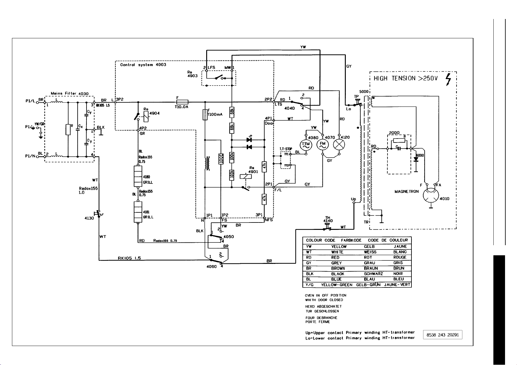
Wiring diagram
07.03.2000 / Page 6 MT 244/1/BLACK Whirlpool Europe
Doc. No: 4812 714 13304 8538 244 99481 Customer Service
4003 Control system
4010 Magnetron
4030 Mainsfilter
4040 Secondary doorswitch
4050 Monitor doorswitch
4060 Primary doorswitch
4070 Motor fan
4080 Motor turntable
SERVICE
4120 Oven lamp
4130 Thermostat oven
4140 Thermostat magnetron
4180 Heatingelement grill
4181 Heatingelement grill
2000 HT capacitor
5000 HT transformer
6000 HT diode
Page 7
SERVICE
Program diagram
Whirlpool Europe MT 244/1/BLACK 07.03.2000 / Page 7
Customer Service 8538 244 99481 Doc. No: 4812 714 13304
Page 8
07.03.2000 / Page 8 MT 244/1/BLACK Whirlpool Europe
Doc. No: 4812 714 13304 8538 244 99481 Customer Service
Program diagram
SERVICE
 Loading...