

Page 1

UD-39
KitchenAid and Maytag 25' SXS
Refrigerators
Models:
KSRJ25FXBL
KSRJ25FXMS
KSRJ25FXMT
MSD2559XEB
MSD2559XEM
MSD2559XEW
Home Appliances
Prepared by: WHIRLPOOL CONSUMER CARE
March 2010
PART NO. W10326038
Page 2

FORWARD
The following service update information is provided to make you more knowledgeable
about KitchenAid and Maytag refrigerators.
Service update information is designed for the experienced service specialist. It keeps
you advised of the most recent improvements and product changes, and allows you to
service these products more efciently.
WHIRLPOOL CORPORATION assumes no responsibility for any repairs made on
our products by anyone other than authorized In-Home Service Professionals.
®Registered trademark/™ Trademarks of Whirlpool, U.S.A., KitchenAid, U.S.A., Jenn-Air, U.S.A.,
or Maytag Corporation or its related companies.
© 2010 All rights reserved.
Whirlpool Corporation, Benton Harbor, MI 49022
- ii -
Page 3

TABLE OF CONTENTS
KITCHENAID AND MAYTAG 25’ SXS AKA ACCELERATOR ....................................... Page 1
Model Number Description ...................................................................................... Page 1
Dimensions .............................................................................................................. Page 1
Flush Dispenser with Stealth Software ........................................................................ Page 2
User Interface Blue and Amber ................................................................................... Page 2
Attaching or Removing Handles .................................................................................. Page 3
Removing Freezer Door ........................................................................................... Page 4-5
Connecting Water Line ................................................................................................ Page 6
Machine Compartment ................................................................................................ Page 7
Freezer Compartment -FC .......................................................................................... Page 8
New Ice Bin Release ................................................................................................... Page 8
Auger Motor Coupling .................................................................................................. Page 9
Removing Auger Motor................ .............................................................................. Page 10
Flush Mount Dispenser ...............................................................................................Page 11
"Victoria" .................................................................................................................Page 11
Removing User Interface........................ ............................................................... Page 12
Removing Dispenser Assembly ............................................................................. Page 13
Removing Dispenser Back Guard ......................................................................... Page 13
Removing Dispenser Switches .............................................................................. Page 14
Control Board Assembly ............................................................................................ Page 15
Control and Power Supply Boards ........................................................................ Page 16
Power Supply Board.............................. ................................................................ Page 16
Control Board Connector Identication .................................................................. Page 17
Control Board Input and Output Voltages/Signals ................................................. Page 18
KITCHENAID STEALTH CONTROL OVERVIEW AND
PROGRAMMING INSTRUCTIONS..........................................................................Page 19-30
Service Diagnostics Mode........................ ............................................................ Page 31-33
Service Sheet... ............................. ....................................................................... Page 34-35
Wiring Diagram............................ ......................................................................... Page 36-38
- iii -
Page 4

KITCHENAID AND MAYTAG 25’ SXS
Dimensions In.
Capacity 25.400
Carton Depth 36 1/4
Carton Height 71 1/4
Carton Width 37 1/4
Cutout Depth (in) 28 7/8
Cutout Height (in) 70 1/4
Cutout Width (in) 36
Depth 33 3/4
Height 69 3/4
Wi dth 35 1/2
Depth Closed Excluding Han dles 30 15/16
Depth Closed Including Handles 33 3/4
Depth Excluding Doors 29 1/4
Depth With Door Open 90 Degree 48 7/8
Dimensions In.
Capacity 25.400
Carton Depth 36 1/4
Carton Height 71 1/4
Carton Width 37 1/4
Cutout Depth (in) 28 7/8
Cutout Height (in) 70 1/4
Cutout Width (in) 36
Depth 33 3/4
Height 69 3/4
Wi dth 35 1/2
Depth Closed Excluding Han dles 30 15/16
Depth Closed Including Handles 33 3/4
Depth Excluding Doors 29 1/4
Depth With Door Open 90 Degree 48 7/8
Gross Weight 295
Height To Top Of Cabinet 68 7/8
Height To Top Of Door Hinge 69 3/4
Width Doors Open 90 Degrees 38 1/2
Width of Cabinet Only 35 1/2
Width with Doors Closed 35 1/2
Dimensions In.
Capacity 25.400
Carton Depth 36 1/4
Carton Height 71 1/4
Carton Width 37 1/4
Cutout Depth (in) 28 7/8
Cutout Height (in) 70 1/4
Cutout Width (in) 36
Depth 33 3/4
Height 69 3/4
Wi dth 35 1/2
Depth Closed Excluding Han dles 30 15/16
Depth Closed Including Handles 33 3/4
Depth Excluding Doors 29 1/4
Depth With Door Open 90 Degree 48 7/8
Gross Weight 295
REFRIGERATORS
Model Number Description*
KSRJ25FXBL 25’ SXS DISPENSING
KSRJ25FXMS 25’ SXS DISPENSING
KSRJ25FXMT 25’ SXS DISPENSING
MSD2559XEB 25’ SXS DISPENSING
MSD2559XEM 25’ SXS DISPENSING
MSD2559XEW 25’ SXS DISPENSING
Inches
*Always refer to Service Sheet and Use and Care Manual for information specic to the refrigerator you are servicing.
44 1/2”
lbs.
1
Page 5
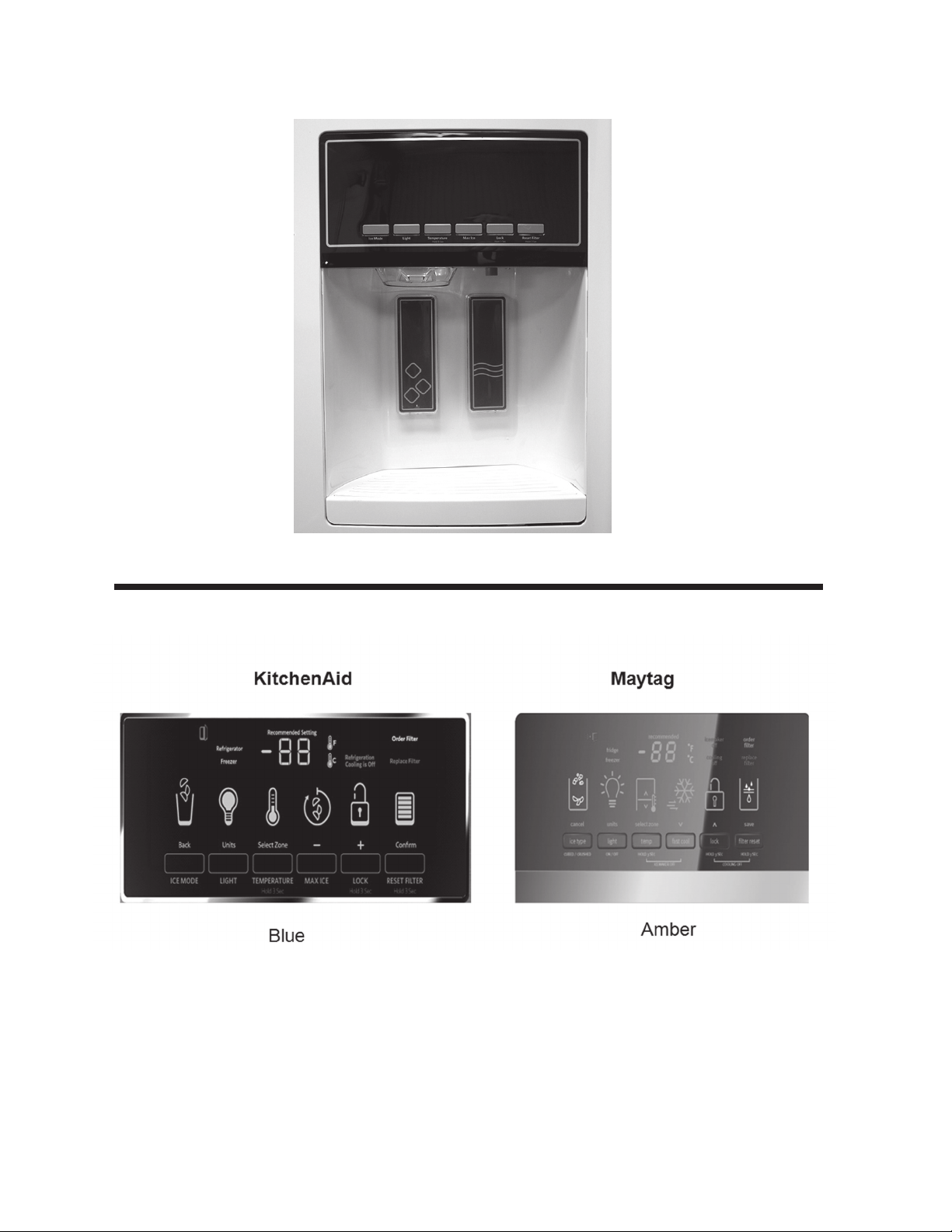
Flush Dispenser with Stealth Software
Flush Dispenser (AKA Victoria) with Stealth Software.
User Interface Blue and Amber
Although the Maytag icons are slightly different and the LED color is amber the
controls function the same.
*Always refer to Service Sheet and Use and Care Manual for information specic to the refrigerator you are servicing.
2
Page 6
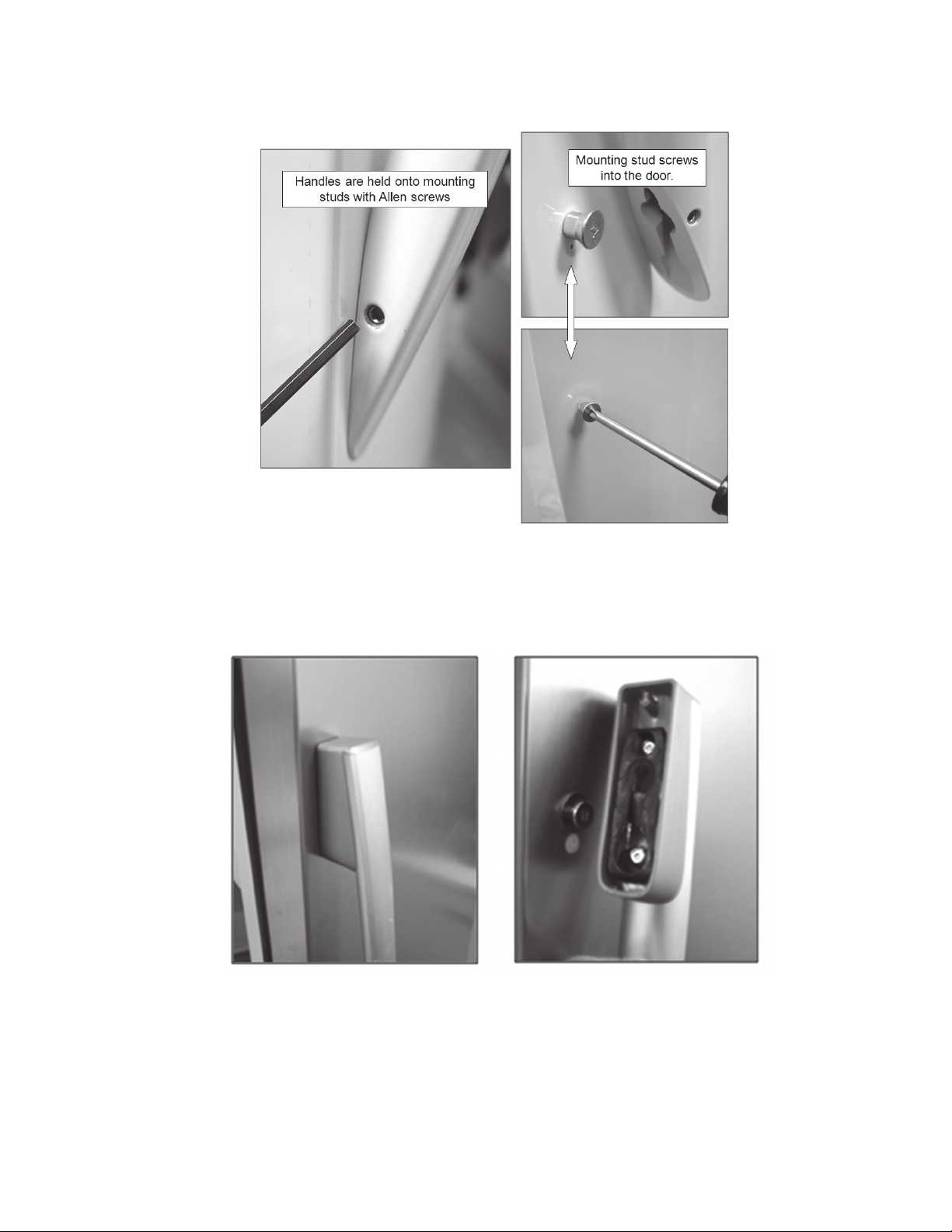
Attaching or Removing Handles
KitchenAid handles are held onto mounting studs with Allen screws.
Maytag handles snap off by lifting handle. The mounting studs screw into door skin.
Maytag Handle Removal: Grasp handle with two hands and lift/jerk up.
*Always refer to Service Sheet and Use and Care Manual for information specic to the refrigerator you are servicing.
3
Page 7

Removing Freezer Door
WARNING
Electrical Shock Hazard
Disconnect power before servicing.
Failure to do so can result in death or
electrical shock.
Replace all parts and panels before operating.
1. Unplug refrigerator or disconnect from power.”
2. Disconnect wiring harnesses and water line.
*Always refer to Service Sheet and Use and Care Manual for information specic to the refrigerator you are servicing.
4
Page 8

Removing Freezer Door (continued)
3. Remove screw and mounting
bracket.
4. Disconnect water tube. 6. Straighten and lay out the har-
5. Disconnect harnesses.
nesses to pull through the hinge.
7. Lift off the freezer door while guiding the water tube and wire harness through
the hinge.
NOTE: Only the harness that is mated with the water tube is routed through the
bottom door hinge.
*Always refer to Service Sheet and Use and Care Manual for information specic to the refrigerator you are servicing.
5
Page 9
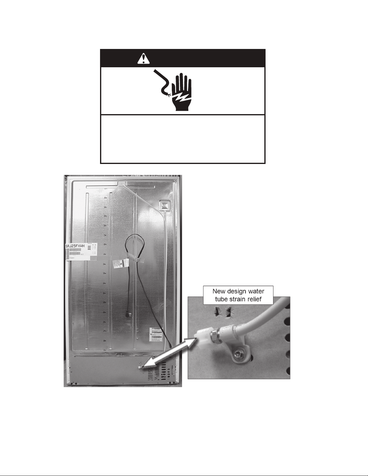
Connecting Water Line
WARNING
Electrical Shock Hazard
Disconnect power before servicing.
Failure to do so can result in death or
electrical shock.
Replace all parts and panels before operating.
1. Unplug refrigerator or discon-
nect power.
2. Remove and discard the cap
from the gray water tube.
3. Using a compression nut and
sleeve, attach the copper tube
to the water inlet.
4. Once secured, tighten the
compression nut. Do not over
tighten.
5. Check the connection by pull
ing on the copper tubing. Turn
on water supply to refrigerator.
Check for leaks. Tighten any
nuts or connections that leak.
*Always refer to Service Sheet and Use and Care Manual for information specic to the refrigerator you are servicing.
6
Page 10

Machine Compartment
WARNING
Electrical Shock Hazard
Disconnect power before servicing.
Failure to do so can result in death or
electrical shock.
Replace all parts and panels before operating.
1. Unplug refrigerator or disconnect power.
Component and refrigeration tubing identication.
2. Plug on start module.
*Always refer to Service Sheet and Use and Care Manual for information specic to the refrigerator you are servicing.
7
Page 11
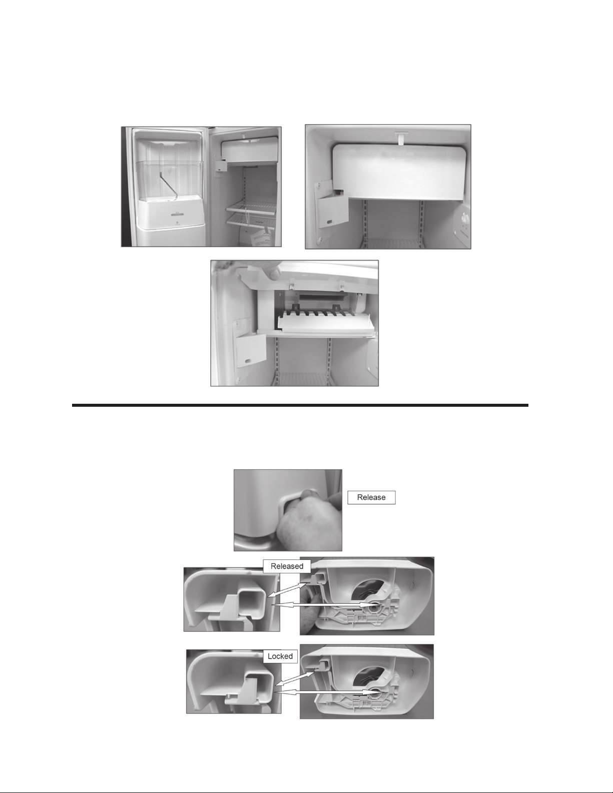
Freezer Compartment -FC
Accelerator has a new small cube icemaker and a special water valve with a 65cc
ow rate.
New Ice Bin Release
The ice bin incorporates a new release. The new design includes a double
latch system for a better engagement.
*Always refer to Service Sheet and Use and Care Manual for information specic to the refrigerator you are servicing.
8
Page 12
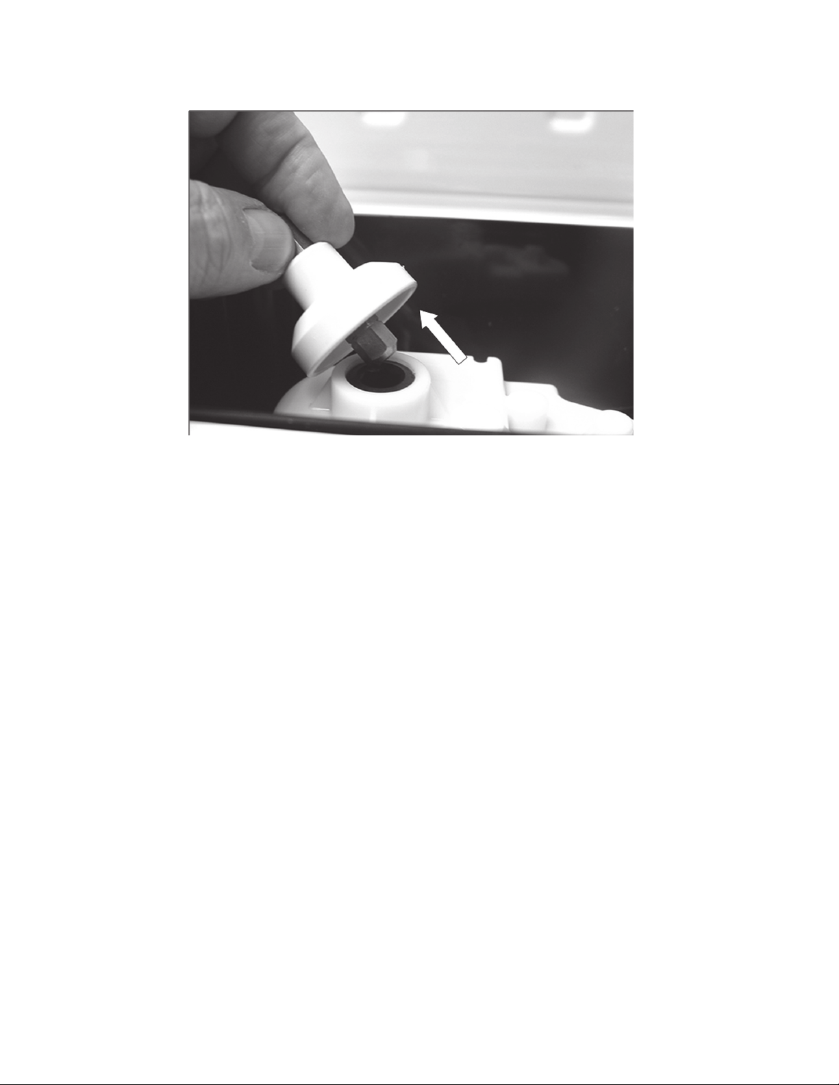
Auger Motor Coupling
Auger motor coupling lifts off motor.
*Always refer to Service Sheet and Use and Care Manual for information specic to the refrigerator you are servicing.
9
Page 13
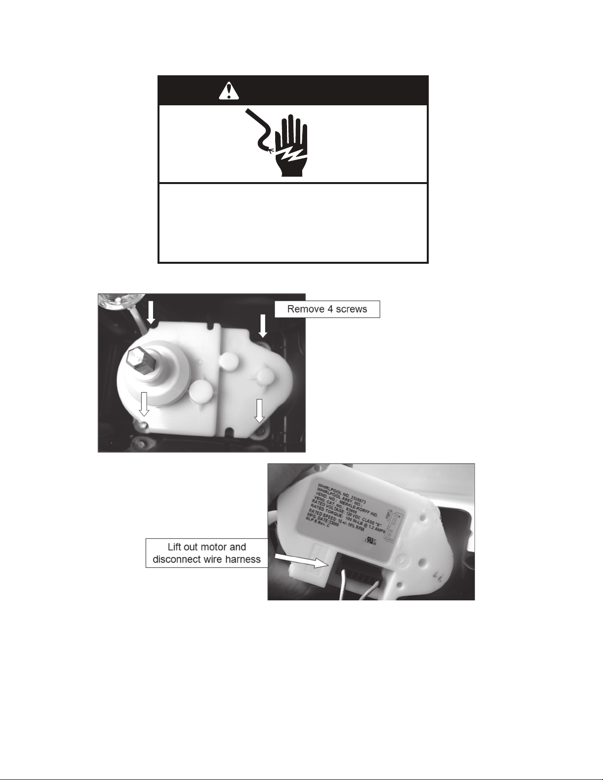
Removing Auger Motor
WARNING
Electrical Shock Hazard
Disconnect power before servicing.
Failure to do so can result in death or
electrical shock.
Replace all parts and panels before operating.
1. Unplug refrigerator or disconnect power.
2.
3.
Harness is only long enough to allow the motor to be lifted high enough to disconnect.
When installing make sure the harness connection is tight.
*Always refer to Service Sheet and Use and Care Manual for information specic to the refrigerator you are servicing.
10
Page 14
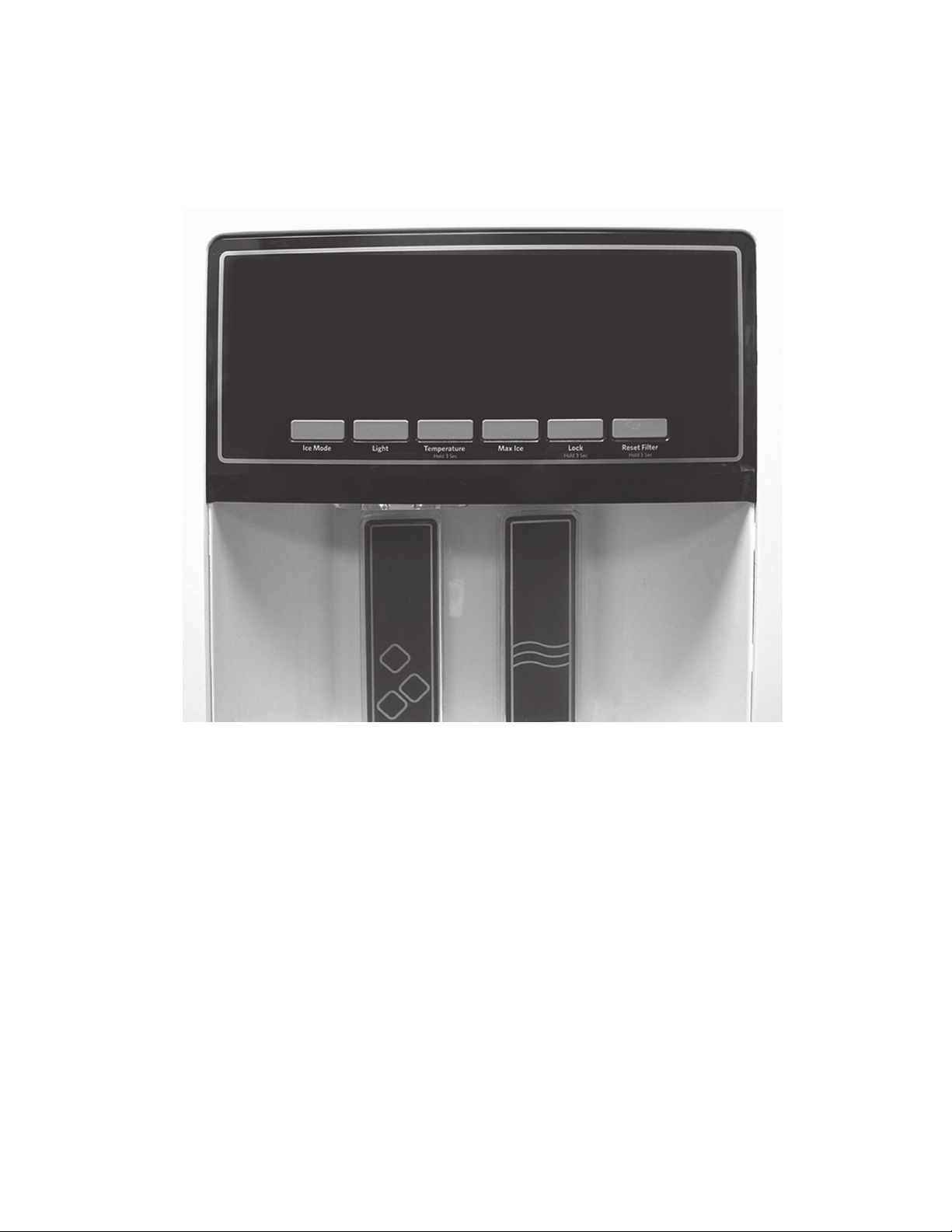
Flush Mount Dispenser
“Victoria”
The new ush design dispenser will migrate across the refrigeration line in 2010.
*Always refer to Service Sheet and Use and Care Manual for information specic to the refrigerator you are servicing.
11
Page 15

Flush Mount Dispenser (continued)
WARNING
Electrical Shock Hazard
Disconnect power before servicing.
Failure to do so can result in death or
electrical shock.
Replace all parts and panels before operating.
Removing User Interface
1. Unplug refrigerator or disconnect power.
2.
3.
*Always refer to Service Sheet and Use and Care Manual for information specic to the refrigerator you are servicing.
12
4.
h
Page 16
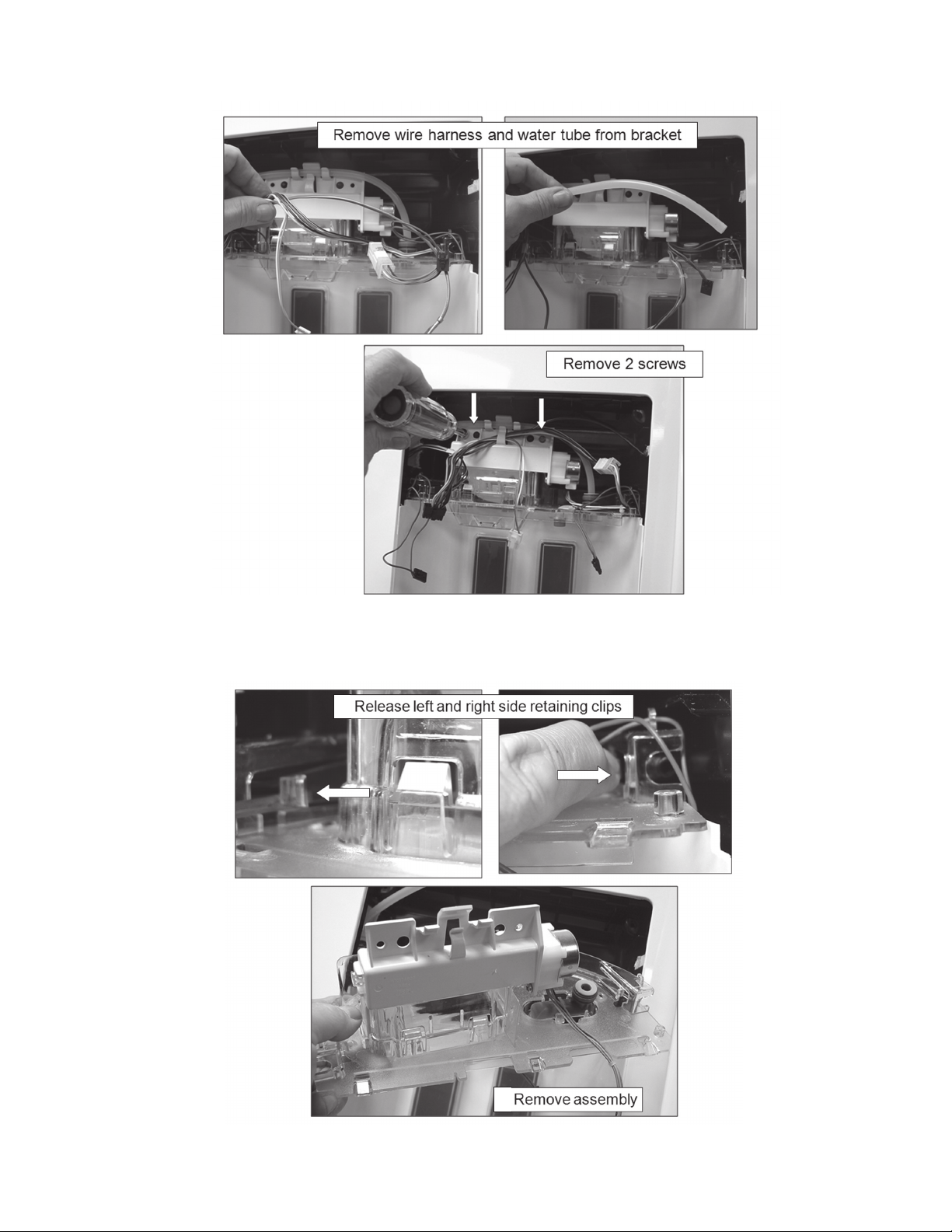
Flush Mount Dispenser (continued)
5.
6.
Removing Dispenser Assembly
The false wall should be slid upward to help disengage the tabs on the left
and right sides.
7.
8.
*Always refer to Service Sheet and Use and Care Manual for information specic to the refrigerator you are servicing.
13
Page 17
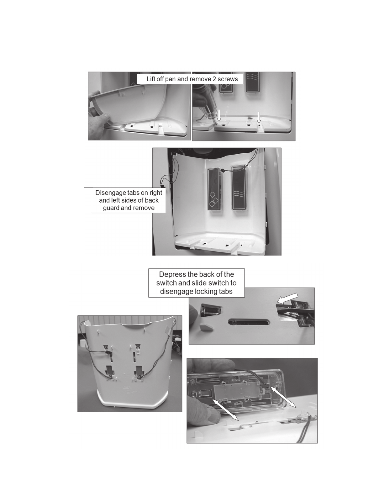
Flush Mount Dispenser (continued)
Removing Dispenser Switches
9.
10.
11.
*Always refer to Service Sheet and Use and Care Manual for information specic to the refrigerator you are servicing.
14
Page 18

Control Assembly
WARNING
DANGER
DANGER
Electrical Shock Hazard
Only authorized technicians should perform
diagnostic voltage measurements.
Failure to follow these instructions can result in
death or electrical shock.
After performing voltage measurements,
disconnect power before servicing.
WARNING
Electrical Shock Hazard
Disconnect power before servicing.
Failure to do so can result in death or
electrical shock.
Replace all parts and panels before operating.
Voltage Measurement Safety Information
When performing live voltage measurements, you must do the following:
� Verify the controls are in the off position so that the appliance does not start when energized.
� Allow enough space to perform the voltage measurements without obstructions.
� Keep other people a safe distance away from the appliance to prevent potential injury.
� Always use the proper testing equipment.
� After voltage measurements, always disconnect power before servicing.
Voltage Measurement Safety Information
1. Unplug refrigerator or disconnect power.
3.
4.
2.
5.
*Always refer to Service Sheet and Use and Care Manual for information specic to the refrigerator you are servicing.
15
Page 19

Control Assembly (continued)
Control and Power Supply Boards
Power Supply Board
*Always refer to Service Sheet and Use and Care Manual for information specic to the refrigerator you are servicing.
16
Page 20
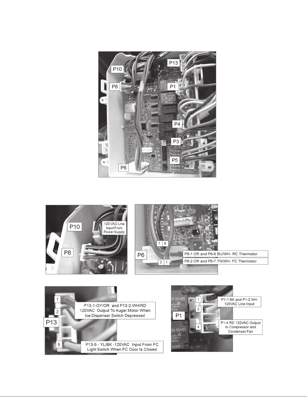
Control Assembly (continued)
Control Board Connector Identication
Control Board Input and Output Voltages/Signals
*Always refer to Service Sheet and Use and Care Manual for information specic to the refrigerator you are servicing.
17
Page 21

Control Assembly (continued)
Control Board Input and Output Voltages/Signals
*Always refer to Service Sheet and Use and Care Manual for information specic to the refrigerator you are servicing.
18
Page 22

Kitchenaid Stealth Control Overview
Fig ure 2 – Maytag Stealth User Interf ace/Amber LED’s except as no ted
.
Fig ure 1 – KitchenAid Stealth User Interf ace/Blue LED’s excep t as noted.
KitchenAid Models: KSRJ25FXBL, KSRJ25FXMS,
KSRJ25FXEB, KSRL25FXBL, KSRL25FXMS and
KSRL25FXEB
Maytag Models: MSD2559XEB, MSD2559XEM and MSD2559XEW
uses the Stealth Control system with minor variations, see figure 2.
and Programming Instructions
Kitchen Aid models, KSRJ25FX**, KSRL25FX**
Maytag model, MSD2559XE* See gure 2.
Note: A KitchenAid display will be used to explain the Control Operation. There are some
cosmetic differences between the KitchenAid and Maytag icons and text. The icons used on the
KitchenAid display are blue. The Maytag display uses amber LED’s. Although the displays are
not identical, the basic operation and programming are the same. See Figures 1 and 2.
*Always refer to Service Sheet and Use and Care Manual for information specic to the refrigerator you are servicing.
19
Page 23

KitchenAid Stealth Control Overview and
Figure 3 – KitchenAid Interface Icon Identification
Sleep Mode
The display screen on the dispenser control panel will turn o automatically and enter “sleep”
mode when the control buttons and dispenser levers have not been used for 2 minutes or more.
See figure 4.
ICE MODE LIGHT MAX ICE LOCK
Hold 3 Sec.
TEMPERATURE
Hold 3 Sec.
RESET FILTER Hold
3 Sec.
Figure 4 – Hibernate/Sleep Mode Screen
While in “sleep” mode, the display is dark
Refrigerator
Cooling is Off
Order Filter
Replace Filter
ICE MODE LIGHT MAX ICE LOCK
Hold 3 Sec.
TEMPERATURE
Hold 3 Sec.
RESET FILTER
Hold 3 Sec.
Back Units Select Zone
-
+
Confirm
Refrigerator
Freezer
Recommended Setting
Figure 3 depicts all the ICONS and Text located on the Display. Specific Icons will be displayed
at different steps during programming as explained in this manual. .
Programming Instructions (continued)
*Always refer to Service Sheet and Use and Care Manual for information specic to the refrigerator you are servicing.
20
Page 24

LIGHT MAX ICE LOCK
Hold 3 Sec.
TEMPERATURE
Hold 3 Sec.
RESET FILTER
Hold 3 Sec.
ICE MODE
Pressing any control button will activate the “Normal/Home ” display screen, without changing
any settings. See figure 5.
After activation, changes to any settings can then be made. If no changes are made within 2
minutes, the display will re-enter “sleep” mode.
Factory Preset Temperatures
The refrigerator and freezer controls are preset at the factory. The factory recommended set
points are 37°F (3°C) for the refrigerator and 0°F (-18°C) for the freezer
To View and Adjust Set Points:
Press and hold the TEMPERATURE button for 3 seconds. When adjust mode is
Activated, the display screen shows the refrigerator set point and “REFRIGERATOR” appears in the
display. See figure 6.
ICE MODE LIGHT MAX ICE LOCK
Hold 3 Sec.
TEMPERATURE
Hold 3 Sec.
RESET FILTER
Hold 3 Sec.
Back Units Select Zone
-
+
Refrigerator
Recommended Setting
Figure 5
Figure 6
KitchenAid Stealth Control Overview and
Programming Instructions (continued)
*Always refer to Service Sheet and Use and Care Manual for information specic to the refrigerator you are servicing.
21
Page 25

KitchenAid Stealth Control Overview and
ICE MODE LIGHT MAX ICE LOCK
Hold 3 Sec.
TEMPERATURE
Hold 3 Sec.
RESET FILTER
Hold 3 Sec.
Back Units Select Zone
-
+
Refrigerator
Recommended Setting
Figure 7
Programming Instructions (continued)
Adjusting Temperature Set Points:
Pressing and holding TEMPERATURE starts a 3 second countdown on the display.
During the countdown using the dispenser cancels the countdown and no dispensing
is permitted. The number ‘3’ blinks 3 times and an ‘invalid’ tone sounds 3 times. The
user has to release both the pad and the button and then press the button again to
start the countdown over.
During the countdown, pressing any other button or releasing the pad cancels the
countdown and the ‘3’ blinks 3 times and the ‘invalid’ tone sounds 3 times. The user
has to start over.
Note: The blinking and toning is synchronized so that the moment the number ‘3’
blinks, the tone is sounded. After 3 seconds, the TEMPERATURE shows up with the
CURRENT refrigerator setting. See Figure 7.
Pressing TEMPERATURE changes between the refrigerator and freezer compartments and displays the current setting. Pressing the ICE MODE pad or after 60
seconds of no activity, the display will revert back to the normal screen.
*Always refer to Service Sheet and Use and Care Manual for information specic to the refrigerator you are servicing.
22
Page 26
KitchenAid Stealth Control Overview and
ICE MODE LIGHT
MAX ICE
LOCK
Hold 3 Sec.
TEMPERATURE
Hold 3 Sec.
RESET FILTER
Hold 3 Sec.
Back Units Select Zone
-
+
Refrigerator
Recommended Setting
Confirm
Lower
Raise
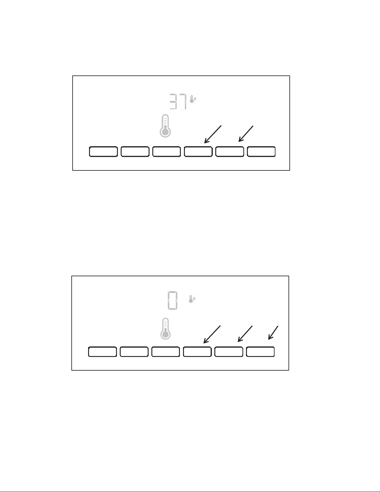
Adjusting Temperature Settings
Press the LOCK pad to raise the temperature set point or press the MAX ICE pad to lower the
temperature set point. See figure 8.
Important: When the temperature is changed, the word “ CONFIRM” above the lter reset pad
illuminates and will FLASH without an audible tone constantly until user presses RESET FILTER,
ICE MODE or after 60 seconds of inactivity. If the user presses TEMPERATURE to change
compartments, C
ON
FIRM still flashes if one of the temps has been changed.
NOTE: To view Celsius temperatures, press the LIGHT button when adjust mode is activated. To
return the display setting to Fahrenheit, press LIGHT again
.
.
Figure 8
Figure 9
ICE MODE LIGHT
MAX ICE
LOCK
Hold 3 Sec.
TEMPERATURE
Hold 3 Sec.
RESET FILTER
Hold 3 Sec.
Back Units Select Zone
-
+
Freezer
Recommended Setting
Confirm
Lower
Raise
Save
Programming Instructions (continued)
Adjusting Temperature Settings
Press the LOCK pad to raise the temperature set point or press
t h e M A X I C E p a d t o l o w e r t h e t e m p e r a t u r e s e t p o i n t . S e e g u r e 8 .
Important: When the temperature is changed, the word “ CONFIRM” above the lter reset
pad illuminates and will FLASH without an audible tone constantly until user presses RESET
FILTER, ICE MODE or after 60 seconds of inactivity. If the user presses TEMPERATURE
t o c h a n g e c o m p a r t m e n t s , C O N F I R M s t i l l a s h e s i f o n e o f t h e t e m p s h a s b e e n c h a n g e d .
NOTE: To view Celsius temperatures, press the LIGHT button when adjust mode is activated. To return the display setting to Fahrenheit, press LIGHT again
.
Freezer Temperature Setting
After viewing (and adjusting if desired) the refrigerator set point, press TEMPERATURE
to change the display to show the freezer set point. When the zone has been changed,
“FREEZER” appears on the display screen. Press LOCK to raise the set point, or press
MAX ICE to lower the set point. When you have nished viewing (and adjusting if desired) both the refrigerator and freezer set points, press FILTER to save the settings.
See gure 9.
*Always refer to Service Sheet and Use and Care Manual for information specic to the refrigerator you are servicing.
23
Page 27
KitchenAid Stealth Control Overview and
LIGHT MAX ICE LOCK
Hold 3 Sec.
TEMPERATURE
Hold 3 Sec.
RESET FILTER
Hold 3 Sec.
ICE MODE
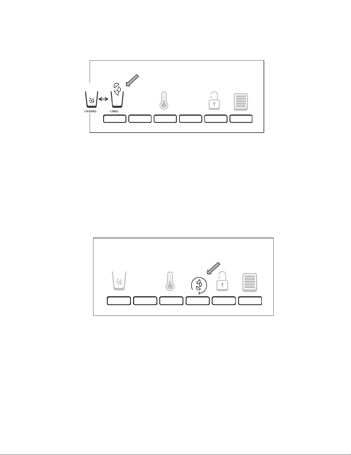
Ice Dispenser:
Ice dispenses from the ice maker storage bin in the freezer when the dispenser lever is pressed.
The ice maker can produce both crushed and cubed ice. Before dispensing ice, select which type of
ice you prefer by pressing the ICE MODE button. The display screen indicates which type of ice is
selected. See figure 10.
For crushed ice, cubes are crushed before being dispensed. This may caus
e a
slight delay when
dispensing crushed ice. Noise from the ice crusher is normal, and pieces of ice may vary in size.
When changing from crushed to cubed, a few ounces of crushed ice will be dispensed along with
the first cubes.
NOTE: Ice may continue to dispense for up to 10 seconds after removing the glass from the lever.
The dispenser may continue to make noise for a few seconds after dispensing.
Figure 10
LIGHT MAX ICE LOCK
Hold 3 Sec.
TEMPERATURE
Hold 3 Sec.
RESET FILTER
Hold 3 Sec.
ICE MODE
LIGHT MAX ICE LOCK
Hold 3 Sec.
TEMPERATURE
Hold 3 Sec.
RESET FILTER
Hold 3 Sec.
ICE MODE
Programming Instructions (continued)
Figure 10
Ice Dispenser:
Ice dispenses from the ice maker storage bin in the freezer when the dispenser lever
is pressed. The ice maker can produce both crushed and cubed ice. Before dispensing ice, select which type of ice you prefer by pressing the ICE MODE button. The
display screen indicates which type of ice is selected. See gure 10.
For crushed ice, cubes are crushed before being dispensed. This may cause a slight
delay when dispensing crushed ice. Noise from the ice crusher is normal, and pieces
of ice may vary in size. When changing from crushed to cubed, a few ounces of
crushed ice will be dispensed along with the rst cubes.
NOTE: Ice may continue to dispense for up to 10 seconds after removing the glass
from the lever.
The dispenser may continue to make noise for a few seconds after dispensing.
Max Ice:
The Max Ice feature assists with temporary periods of heavy ice use by increasing ice
production over a 24-hour period.
IMPORTANT: This feature only works if the ice maker is turned on. Press MAX ICE to
turn on the Max Ice feature. When the feature is on, the Max Ice icon will appear on
Figure 11
the dispenser display screen. See gure 11.
The Max Ice setting will remain on for 24hours unless manually turned off. To manually turn off the Max Ice feature, press MAX ICE again or adjust the freezer temperature set point. The MAX ICE icon will disappear when the feature is off.
NOTE: If increased ice production is desired at all times, change the freezer set point
to a lower setting. Setting the freezer to a colder temperature may make some foods,
such as ice cream harder.
*Always refer to Service Sheet and Use and Care Manual for information specic to the refrigerator you are servicing.
24
Page 28

KitchenAid Stealth Control Overview and
LIGHT MAX ICE LOCK
Hold 3 Sec.
TEMPERATURE
Hold 3 Sec.
RESET FILTER
Hold 3 Sec.
ICE MODE
Programming Instructions (continued)
Figure 12
Dispenser Light:
When you use the dispenser, the light will automatically turn on. If you want the light
to be on continuously, you may choose either ON or DIM.
The display screen indicates which mode is selected. See gure 12.
ON: Press LIGHT to turn the dispenser light on at 100%
DIM: Press LIGHT a second time to select DIM mode. The dispenser light will remain
on, but at a lower 50% intensity.
OFF: Press LIGHT a third time to turn the dispenser light off
NOTE: If the setting is changed it will remain that way.
*Always refer to Service Sheet and Use and Care Manual for information specic to the refrigerator you are servicing.
25
Page 29
KitchenAid Stealth Control Overview and
LIGHT MAX ICE LOCK
Hold 3 Sec.
TEMPERATURE
Hold 3 Sec.
RESET FILTER
Hold 3 Sec.
ICE MODE
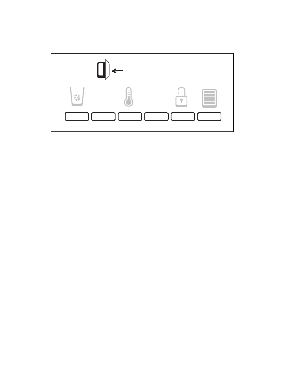
Door Open Icon
Figure 13
Programming Instructions (continued)
Door Open Alarm
The Door Open Alarm feature sounds an alarm when the refrigerator or freezer door
is open for 5 minutes and the product cooling is turned on. The alarm will repeat every
2 minutes. Close both doors to turn it off. The feature then resets and will reactivate
when either door is left open again for 5 minutes.
Details:
When a door is open for 5 minutes and the cooling function is on:
The Door Open Icon and the normal screen is displayed.
The Door Open chime is sounded 3 times.
The Door Open Icon appears and blinks 7 times and then becomes constant.
If a door is left open, every 2 minutes, the Door Open chime sounds 3 times, the
Door Open icon blinks 7 times and then becomes constant.
Note: since inactivity to sleep is also two minutes, the door open situation shall overwrite the sleep mode. In other words, the UI will not go to the sleep mode if it is in the
Door Open mode.
When the door open alert condition is met (door open for 5 min), pressing any button
on the control panel at any time will turn off the Door Open Alert Chime.
The other door open functions, ashing door open icon, and the door reset timer continue until the next door open alert occurs. This will continue until the both door are
closed.
NOTE: To mute the audible alarm while keeping the doors open, such as while cleaning the inside of the refrigerator, press any button on the control panel. The alarm
sound will be temporarily turned off, but the Door Open icon will still be displayed on
the dispenser control panel. See gure 13.
*Always refer to Service Sheet and Use and Care Manual for information specic to the refrigerator you are servicing.
26
Page 30

KitchenAid Stealth Control Overview and
LIGHT MAX ICE LOCK
Hold 3 Sec.
TEMPERATURE
Hold 3 Sec.
RESET FILTER
Hold 3 Sec.
ICE MODE
Figure 14
Programming Instructions (continued)
Dispenser Lock:
The dispenser can be turned off for easy cleaning or to
avoid unintentional dispensing by small children and pets.
NOTE: The lock feature does not shut off power to the refrigerator, to the ice maker,
or to the dispenser light. It simply deactivates the controls and dispenser levers.
Details
Pressing and holding LOCK starts a 3 second countdown on the display. During the
countdown, using the dispenser cancels the countdown and no dispensing is permitted. During the countdown pressing any other button or releasing the Lock button
cancels the countdown.
After 3 seconds, the UI is locked. (See gure 14) No function or dispensing is allowed except for cooling off. No status is displayed except for LOCK, Door Open, and
Cooling Off . Pressing any button or pad (except for LOCK or the COOLING OFF
key sequence) will wake up the lock screen if it has gone to sleep. The lock icon will
blink three 3 times and the “invalid” tone sounds 3 times.
Pressing and holding LOCK for 3 seconds unlocks the UI and the normal screen (if
cooling is not off) is displayed depicting the ice mode, light status ,lock status, or any
alert icons exactly as before it was locked.
*Always refer to Service Sheet and Use and Care Manual for information specic to the refrigerator you are servicing.
27
Page 31

LIGHT MAX ICE LOCK
Hold 3 Sec.
TEMPERATURE
Hold 3 Sec.
RESET FILTER
Hold 3 Sec.
ICE MODE
Figure 15
Cooling is Off
KitchenAid Stealth Control Overview and
Programming Instructions (continued)
Cooling Off Mode
Pressing and holding both LOCK and RESET FILTER simultaneously (Figure 15)
starts a 3 second countdown. During the countdown, using the dispenser cancels
the countdown and no dispensing is permitted.
After 3 seconds, the ‘cooling off’ icon appears and ashes 7 times then remains on.
All the rest of the icons and door open turn off.
Exception: if the UI is locked the user can still turn cooling off. The ‘COOLING OFF’
icon will be displayed along with the lock icon. The only keys available to the user
are the lock key to unlock the control which returns to the standard cooling mode.
When any other key is pressed, an error beep will be sound.
If the customer is in “normal mode” (not in locked mode) and the customer turns cooling off, only the cooling off icon will show. The only
keys available to the customer is the cooling on/off key sequence combination. When any other keys are pressed, an error beep will sound.
The Cooling is Off screen will stay on all the time and does not go to sleep. If Cooling
is Off when power is interrupted, it will remain in the Cooling is Off when power is
restored.
During “COOLING OFF” (if the UI is not locked), ice and water dispensing is allowed.
Cooling On Mode
Pressing and holding LOCK and RESET FILTER again for 3 sec turns the cooling
on. After cooling is turned on, the normal screen is displayed with the ice mode, light
status, lock status, lter status, or any alerts icons displayed exactly as before cooling was shut off.
*Always refer to Service Sheet and Use and Care Manual for information specic to the refrigerator you are servicing.
28
Page 32

Figure 16
LIGHT MAX ICE LOCK
Hold 3 Sec.
TEMPERATURE
Hold 3 Sec.
RESET FILTER
Hold 3 Sec.
ICE MODE
Order
Replace
KitchenAid Stealth Control Overview and
Programming Instructions (continued)
Water Filter Status Light:
The water lter status light will help you know when to change your water lter.
When the dispenser control panel’s water lter status display changes to “ORDER,”
this tells you that it is almost time to change the water lter cartridge.
Replace the water lter cartridge when the water lter status display changes to
“REPLACE.” The lter should be replaced at least every 6 months, depending on your
water quality and usage. Note: If water ow to your water dispenser or ice maker
decreases noticeably, change the lter sooner.
After changing the water lter, reset the status light.
Details:
Pressing and holding RESET FILTER starts the 3 second countdown. Using the dispenser cancels the countdown and no dispensing is permitted. The number ‘3’ blinks
3 times and the ‘invalid’ tone sounds 3 times and user has to release both the pad
and the button and press the button again to start it over
After 3 seconds, the BLUE WATER BARS in the Icon ash and an audible tone will
not sound three times. When the system is reset, the “ORDER” and “REPLACE”
icons will disappear from the display screen. See gure 16.
Note: Users can reset the lter status at any stage.
*Always refer to Service Sheet and Use and Care Manual for information specic to the refrigerator you are servicing.
29
Page 33

KitchenAid Stealth Control Overview and
Programming Instructions (continued)
Showroom Mode:
Pressing and holding LIGHT and MAX ICE starts a 3 second countdown. During the
countdown, pressing any other button or releasing a pad cancels the countdown.
Details:
After 3 seconds, the control enters the showroom mode and the cooling system turns
off. When in the showroom mode, COOLING OFF and WFI icons stay off all the time,
while the Door Open icon appears whenever door is open, however there is no door
open audible alert.
No ice or water dispensing is allowed , an ‘invalid’ tone sounds if a pad is pressed or
pressed and held.
User is not allowed to turn cooling on or off. If attempted invalid tone sounds.
Pressing ICE MODE toggles cubed and crushed,
Pressing LIGHT toggles off/on/dim ; lighting changes accordingly.
The user can enter the Temperature Setting menu, which works the same as previously described and the temperature will be stored. However, the moment the showroom mode is exited, the temp will be set back to default.
After 1 minute in a temperature screen without activity the control returns to the nor-
mal screen.
Please note that ‘Cooling is Off’ text will never be lit in the showroom mode
Note: The UI never goes to sleep under any circumstances.
Exiting the Showroom Mode:
Pressing and holding LIGHT and MAX ICE again for 3 sec OR unplugging and plugging in the power cord exits the showroom mode and returns to normal operation.
*Always refer to Service Sheet and Use and Care Manual for information specic to the refrigerator you are servicing.
30
Page 34

Figure 1
Digit 1 Digit 2
Figure 2
Service Diagnostics Mode
To Enter Service Diagnostics Mode:
Press SW1 and SW2 simultaneously for 3
seconds, see figure 1. There will be a 3,2,1
countdown on the display, see figure 2. Release
both buttons when "Beep" sounds. Unit must not
be in "Lockout" prior to entering the Service
Diagnostic Mode. The display will show "0I" to
indicate the control is in step1 of the diagnostics
routine.
Switch Diagram
Display Digits
Cooling diagnostics are steps 1 through 7. Dispensing diagnostics are steps 8
through 30. Each step must be manually advanced.
Press SW5 to advance to the next step in sequence.
Press SW4 to return to the previous step. Diagnostics will begin at Step 1.
Step Display
Amber LED's
Status Display
Red LED's
This is an internal board test. The board will check
the resistance value of the Thermistor and display
the results in the RC Temperature Display.
01 = Pass
02 =Open
03 = short
This is an internal board test. The board will check
the resistance value of the Thermistor and display
the results in the RC Temperature Display.
Suggested Diagnostics Routine
Cooling system steps 1-7
Dispensing system steps 8-30
Component Status Indicator
Each step is displayed as 2 digits in the dispenser display. The step results are displayed using the same 2 digits
but 2 seconds after the step number is displayed. The step number is identified using Amber LED's.
In the diagnostic mode, all buttons and pad inputs are ignored and all inputs are off except as described in the
actions of each step.
Note: The ice door motor cycles one minute after an ice dispense is initiated.
Service Note: If the control does not respond, disconnect the refrigera
tor from power for 10 second. Reconnect to
power and wait 10 seconds before entering the Service Diagnostics.
To Exit Service Diagnostics Mode. Do one of the following options:
1. Press SW1 and SW2 simultaneously for 3 seconds.
2. Disconnect the refrigerator from power and reconnect.
3. Allow 20 minutes for the program to automatically time out.
Following the exit from the diagnostics mode, the control will resume normal operation.
The cooling diagnostics are listed first followed by the dispensing diagnostics.
1
Step
Number
FC Thermistor
2
RC Thermistor
Component
Tested
SW1
SW2
SW3
SW4
SW5
SW6
Service Diagnostics Mode
NOTE: This is an example of the information on the Technical Data Sheet shipped
with the refrigerator.
*Always refer to Service Sheet and Use and Care Manual for information specic to the refrigerator you are servicing.
31
Page 35
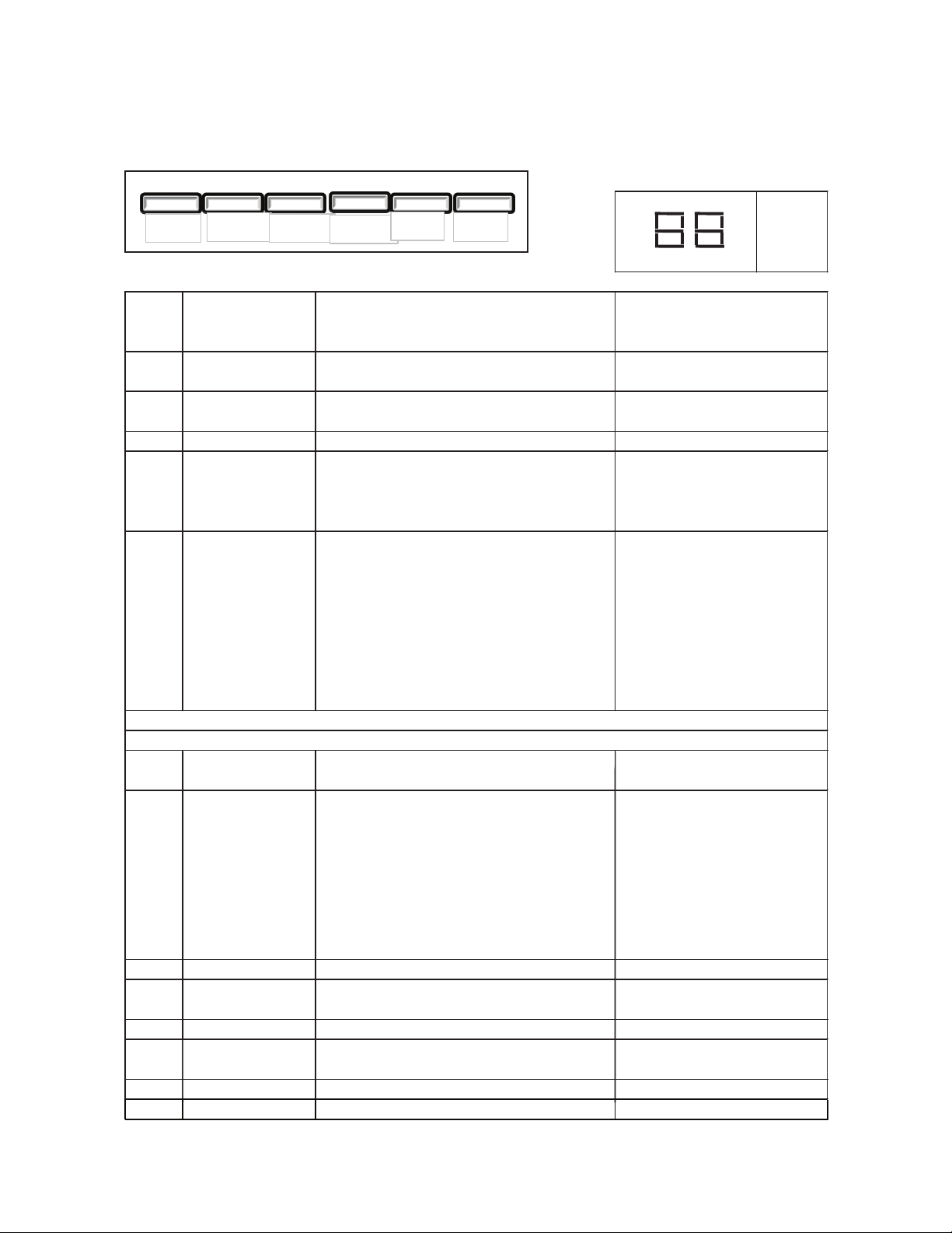
Service Diagnostics Mode (continued)
Service Diagnostics - Cont.
Digit 1 Digit 2
5
Digit 1 Digit 2 SW Pressed
1 Blank SW 1
2 Blank SW 2
3 Blank SW 3
6 Blank SW 6
Blank 1 Ice Pad
Blank 2 Water Pad
Blank 3
Ice
and Water
10
12
14
13
01=ON
02=OFF
Does Not Apply
This step is automatically by-passed
Does Not Apply
Does Not Apply
This step is automatically by-passed
Does Not Apply
Dispenser Housing
Heater Status
Displays the Dispenser Housing Heater status on the
UI display. Press SW3 to change status.
Does Not Apply
This step is automatically by-passed
Does Not Apply
Pressing SW3 will change the dispenser light setting
from OFF(0%) to ON(100%) to DIM(50%)
9
UI Button/Pad Test
Displays the User Interface Buttons and Ice and
Water Pads status as described in the Component
Status Indicator column.
Note: Do not use SW4 and SW5 as these are used
only to navigate through the Service Diagnostics.
11
Dispenser Lighting
Blank
Dispensing System Steps 8-30
Verify that all LED indicators and UI digits turn on
automatically
8
All UI indicators
All indicators ON
7
Defrost Mode
01=ADC ON
02= Basic Mode ON - 8 hour Timer
Important: If Bi-Metal is by-passed for testing. Do Not Overheat the Evaporator Area
Switch Diagram
Step
Amber LED's
Status
Red LED's
Display Digits
Press SW5 to advance to the next step in sequence.
Blank= Waiting for validation
01= Bimetal Closed
02=Bimetal Open
The Defrost Mode can be activated by using SW3. In
the ADC Mode the refrigerator will automatically
defrost after a minimum of 8 hours of compressor run
time and up to maximum of 96 hours of compressor
run time, depending upon product usage. In Basic
Mode the product will automatically defrost after 8
hours of compressor runtime. The Defrost Mode must
be set to ADC ON before exiting the Service
Diagnostic Mode. Press SW5 to indicate the
completion of this step and to continue with the
dispenser ser
vice routine.
Component Status Indicator
Cooling system steps 1-7
Dispensing system steps 8-30
02=OFF
This step is automatically by-passed
Does Not Apply
01=ON
01=Fan On, Air Baffle open
02=Fan On, Air Baffle closed
6
Defrost heater
and Bimetal
Compressor and
Condenser Fan Motor
Does Not Apply
Press SW4 to return to the previous step.
Step
Number
Component
Tested
Suggested Diagnostics Routine
Line voltage switched to compressor and condenser
fan from control board
Evaporator fan motor
and air baffle motor
Verify air flow from evaporator fan. Check to see if
the air baffle opens and closes
3
4
Line voltage switched to components from board,
verify heater operation. If Bimetal is open, it will need
to be by-passed for heater to operate.
SW1
SW2
SW3
SW4
SW5
SW6
15
Does Not Apply
This step is automatically by-passed
Does Not Apply
NOTE: This is an example of the information on the Technical Data Sheet shipped with
the refrigerator.
*Always refer to Service Sheet and Use and Care Manual for information specic to the refrigerator you are servicing.
32
Page 36
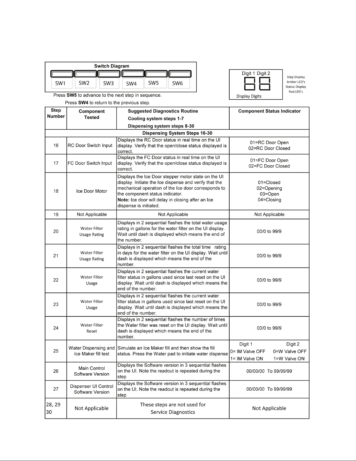
Service Diagnostics Mode (continued)
NOTE: This is an example of the information on the Technical Data Sheet shipped with
the refrigerator.
*Always refer to Service Sheet and Use and Care Manual for information specic to the refrigerator you are servicing.
33
Page 37

Service Sheet
NOTE: This is an example of the information on the Technical Data Sheet shipped with
the refrigerator.
*Always refer to Service Sheet and Use and Care Manual for information specic to the refrigerator you are servicing.
34
Page 38

Service Sheet (continued)
NOTE: This is an example of the information on the Technical Data Sheet shipped with
the refrigerator.
*Always refer to Service Sheet and Use and Care Manual for information specic to the refrigerator you are servicing.
35
Page 39

Wiring Diagram
NOTE: This is an example of the information on the Technical Data Sheet shipped with
the refrigerator.
*Always refer to Service Sheet and Use and Care Manual for information specic to the refrigerator you are servicing.
36
Page 40

Wiring Diagram (continued)
NOTE: This is an example of the information on the Technical Data Sheet shipped with
the refrigerator.
*Always refer to Service Sheet and Use and Care Manual for information specic to the refrigerator you are servicing.
37
Page 41

Wiring Diagram (continued)
*Always refer to Service Sheet and Use and Care Manual for information specic to the refrigerator you are servicing.
38
 Loading...