

Whirlpool MK 8137 XEQ, MK 8137 XEB Installation Instructions
//l(STALLAT/O/V /NSTRUCT/ON
FOR USE WITH WHIRLPOOL MICROWAVE OVEN MODELS: MC8131XEQ. MC8131XEB
[ UL LISTED FOR USE OVER ELECTRIC HEAT SOURCE INCLUDING MODELS: RBS270PD. RBS275PD. RBS277PD. KEBl171 D, KEBS177D 1
FOR WHIRLPOOL TRIM-KIT MODELS: MK8137XEQ. MK8137XEB
(KEEP FOR
FUTURE REFERENCES
1 STEP
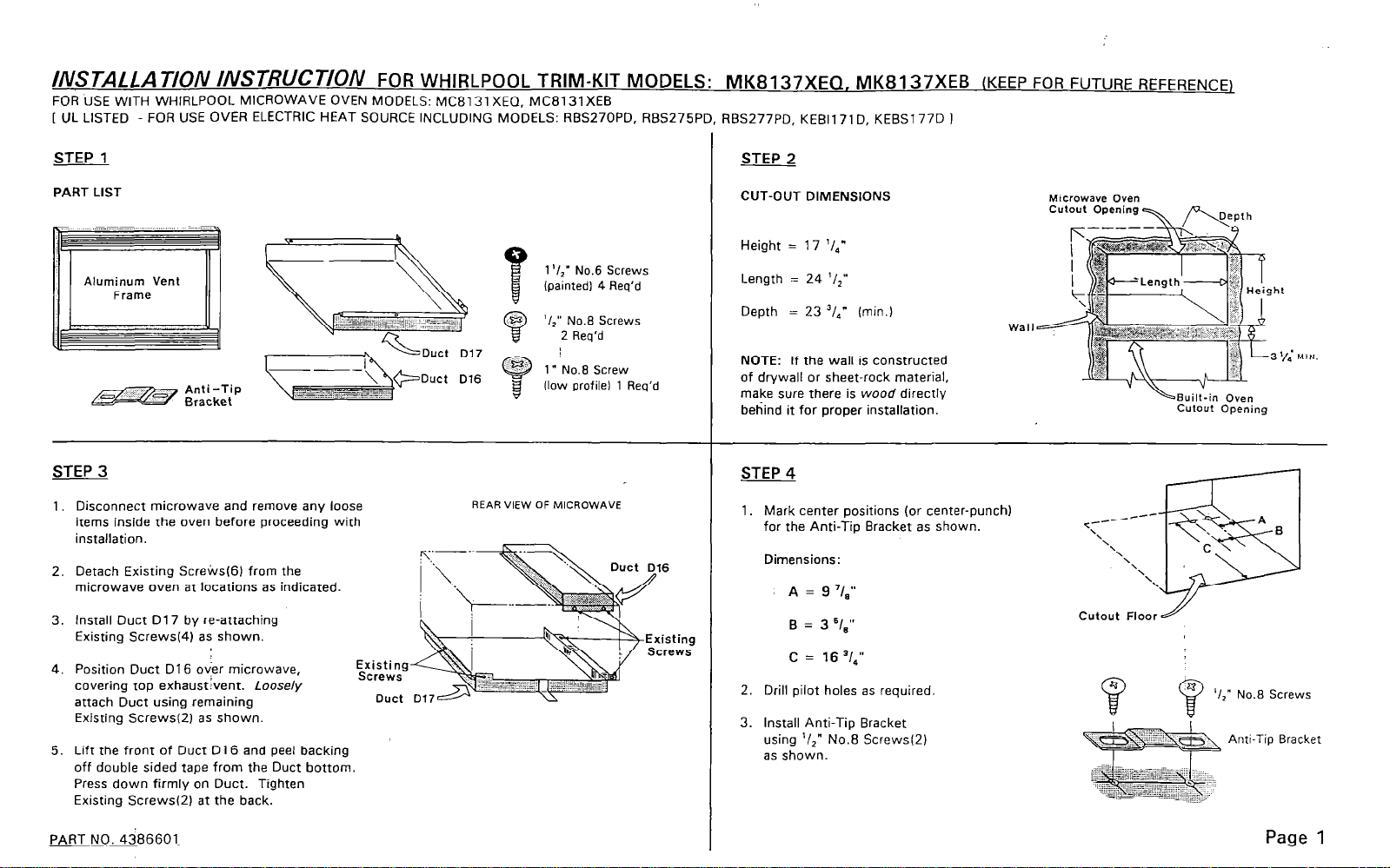
PART LIST
Aluminum Vent
STEP 3
1, Disconnect microwave and remove any loose
items inside the oven before proceeding with
installation.
2. Detach Existing Screivs(6) from the
microwave oven at locations as indicated.
3. Install Duct D17 by re-attaching
Existing Strews(4) as shown.
4. Position Duct D16 over microwave,
covering top exhaustivent. Loosely
attach Duct using remaining
Existing Strews(2) as shown.
5. Lift the front of Duct D16 and peel backing
off double sided tape from the Duct bottom.
Press down firmly on Duct. Tighten
Existing Screwsf2) at the back.
1 ‘/2” No.6 Screws
(painted1 4 Req’d
‘I ” No.8 Screws
2
2 Req’d
REAR VIEW OF MICROWAVE
2 STEP
CUT-OUT DIMENSIONS
Height = 17 ‘I.,”
Length = 24 ‘/>”
Depth = 23 J/4” (min.)
NOTE: If the wall is constructed
of drywall or sheet-rock material,
make sure there is wood directly
behind it for proper installation.
1. Mark center positions (or center-punch)
for the Anti-Tip Bracket as shown.
Dimensions:
A = 9 7/a”
B = 3 =18”
C = 16 ‘14”
2. Drill pilot holes as required.
3. Install Anti-Tip Bracket
using ‘/z” No.8 Screws(Z)
as shown.
Cutout Floor
0
LBuilt-in Oven
CUlOUt Opening
i ‘I,” No.8 Screws
Anti-Tip Bracket
PART NO. 4386601
Page 1
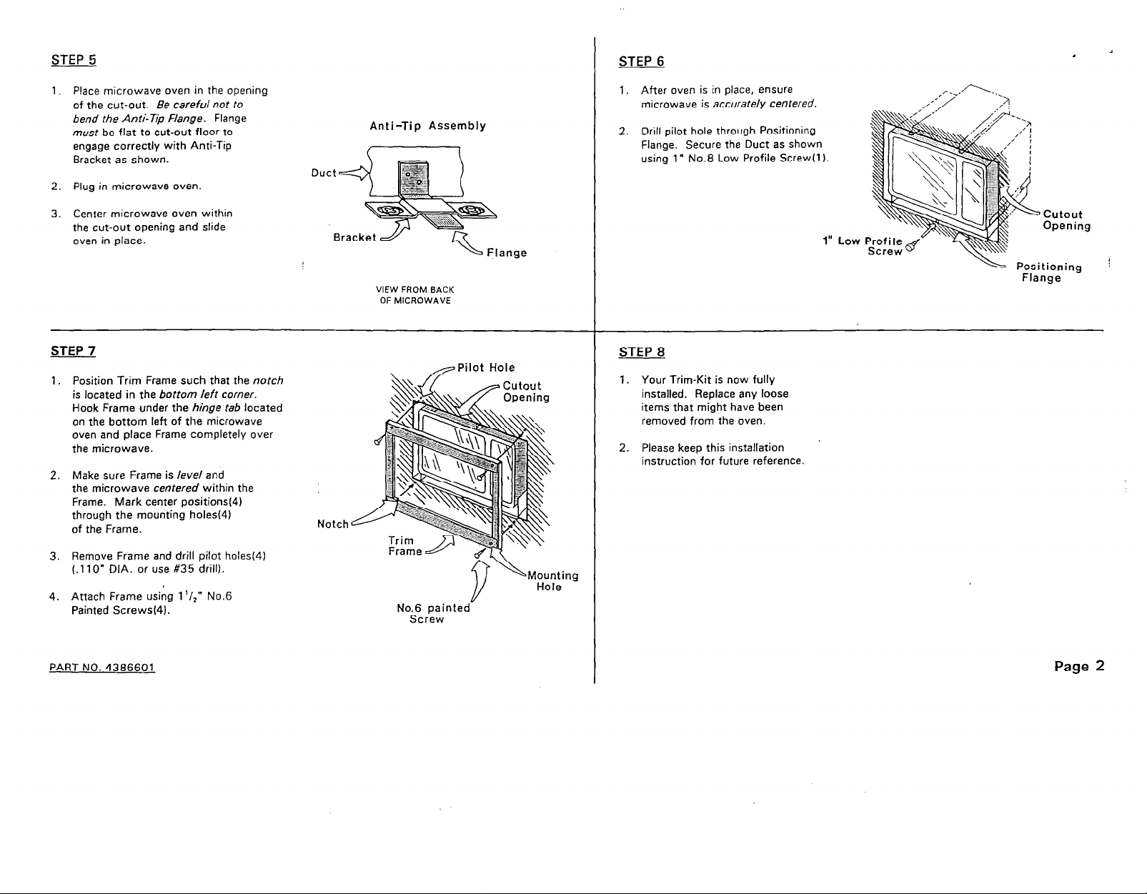
STEP 5
STEP 6
1. Place microwave oven in the opening
of the cut-out. Be careful not to
bend the Anti-Tip Flange. Flange
must be flat to cut-out floor to
engage correctly with Anti-Tip
Bracket as shown.
2. Plug in microwave oven
3. Center microwave oven within
the cut-out opening and slide
oven in place.
STEP 7
1.
Position Trim Frame such that the notch
is located in the bottom kff comer.
Hook Frame under the hinge fab located
on the bottom left of the microwave
oven and place Frame completely over
the microwave.
Make sure Frame is /ewe/ and
2.
the microwave centered within the
Frame. Mark center positions(4)
through the mounting holes(41
of the Frame.
Notch
Anti-Tip Assembly
‘& Flange
VIEW FROM BACK
OF MICROWAVE
/Pilot Hole
\
1, After oven is in place, ensure
microwave is accurately centered.
2. Drill pilot hole through Positioning
Flange. Secure the Duct as shown
using 1” No.8 Low Profile Screw(l).
STEP 8
1. Your Trim-Kit is now fully
installed. Replace any loose
items that might have been
removed from the oven.
2. Please keep this installation
instruction for future reference.
cutout
Opening
L Positioning
Flange
Remove Frame and drill pilot boles(4)
3.
t.110” DIA. or use #35 drill).
Attach Frame using 1 ‘/1” No.6
4.
Painted Screwsf4).
PART NO. 4386601
No.6 painted
Screw
I/
I/
Hole -
Page 2
 Loading...