

Whirlpool MK6124XAQ1, MK6124XAB1 Installation Instructions
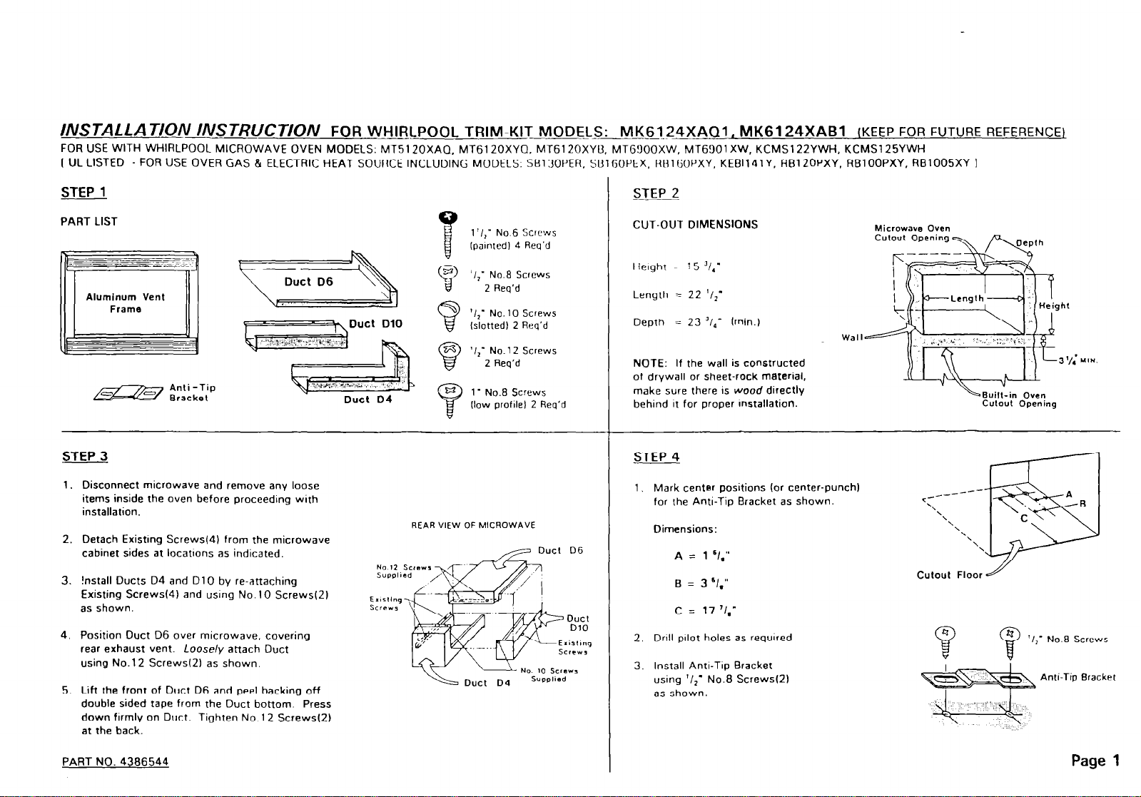
INSTALLATION INSTRUCT/ON
FOR USE WITH WHIRLPOOL MICROWAVE OVEN MODELS: MT51 20XAQ MT61 20XY0. MT61 2OXYB. MTG!lOOXW, MT6901 XW, KCMSl22YWH. KCMSl25YWH
I UL LISTED - FOR USE OVER GAS & ELECTRIC HEAT SOURCE INCLUDING MODELS. SB130PER. SBlGOPEX. HBIGOPXY, KEBl141y. RBlZOPXY. RBlOOPXY, RB1005XY I
FOR WHIRLPOOL TRIM-KIT MODELS: MK6124XAQ1, MK6124XABl
(KEEP FOR FUTURE REFERENCE)
STEP 1
PART LIST
\F, Duct DlO
STEP 3
1. Disconnect microwave and remove any loose
items inside the oven before proceeding with
installation.
2. Detach Existmg Screws(41 from the microwave
cabinet sides at locatlons as indicated.
3. !nstall Ducts D4 and DlO by re-attaching
Existing Strews(4) and usng No. 10 Screws(Z)
as shown.
Duct D4
no 12 Screw
1 ‘I,- No.6
IpaInted 4 Req’d
‘I,’ No.@ Screws
E-$
(7
REAR VIEW OF MICROWAVE
2 Req’d
‘I,’ No. 10 Screws
(slotted) 2 Req’d
‘I,- No.1 2 Screws
2
Req’d
1 - No.8 Screws
(low profllel 2 Req’d
Screws
STEP 2
CUT-OUT DIMENSIONS
- i5 '1,'
Height
Length = 22 ‘I>’
Depth = 23 ‘I,’ (min.1
NOTE: If the wall is constructed
of drywall or sheet-rock material,
make sure there is wood directly
behind It for proper installation.
4 STEP
1, Mark center positions (or center-punch)
for rhe Anti-Tip Bracket as shown.
Dimensions:
A = 1 ‘/,”
c = 17 ‘I,”
Wall
Microwave Oven
Culout Opening
<-----
‘\
‘\\
Cutoul Floor H
Culovl Opening
---
\
‘1
\
‘.
4. Position Duct D6 over microwave, covering
rear exhaust vent. Loosely attach Duct
using No.1 2 Screws(Z) as shown.
5. Lift the front of Duct D6 and peel backing off
double sided tape from the Duct bottom. Press
down firmly on Duct. Tighten No. 12 Screws(Z)
at the back.
PART NO. 4306544
2. Dnll pllot holes as required
3. Install Anti-TIP Bracket
using ‘/11 No.8 Screwsl2)
as shown.
$) ‘I,-
No.6 Screws
Anti-Tip
Page 1
Bracket

5 STEP
1, Place microwave oven in the openmg
of the cut-out. Be
bend the Anti-Tip Flange. Flange
must be flat to cut-out floor to
engage correctly with Anti-Tip
Bracket as shown.
2. Plug in microwave oven
3 Center mrcrowave oven within
the cut-out opening and slide
oven in place.
c~reh/ nof IO
Anti-Tip Assembly
\ Flange
STEP 6
After oven is rn place, ensure
1
mrcrowave IS accurately centered.
2. Drill prlot holes through Positioning
Flanges. Secure the Ducts as shown
using 1’ No.8 Low Profde Screws(Z).
1” 1
7 STEP
1.
Place Trim Frame over microwave
Make sure Frame is level and
2.
the microwave centered within the
Frame. Mark center positionsf4)
through the mounting holesf4)
of the Frame.
Remove Frame and drill pilot holesf4)
3.
f.1 10’ DIA or use #35 drill).
Attach Frame using 1 1/Z- No.6
4.
Painted Screwsl4).
PART NO. 4306544
VIEW FROM BACK
OF MICROWAVE
#Pilot Hole
\
No.6 painledY
Screw
AMounting
Holo
STEP 8
--
1. Your Trim-Krt is now fully
installed. Replace any loose
items that might have been
removed from the oven.
2. Please keep thrs installation
instruction for future reference
Flanges -
Page 2
 Loading...