

Whirlpool MK3094XAQ, MK3094XAB Installation Instructions
/NSTALUTlON
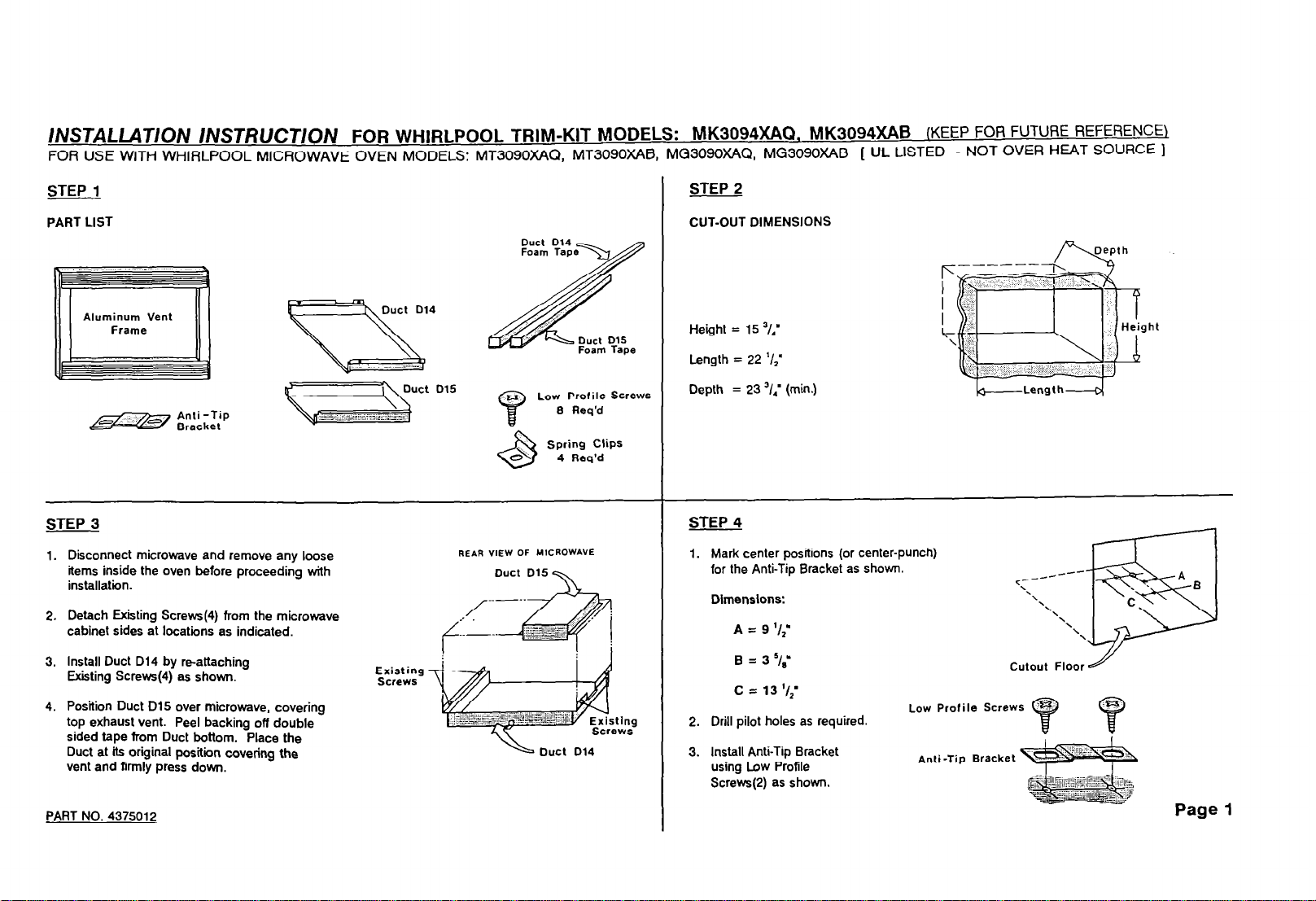
FOR USE WITH WHIRLPOOL MICROWAVE OVEN MODELS: MT309OXfd& MT3090XAB, MG3090XAQ, MG3090XAB [ UL LISTED - NOT OVER HEAT SOURCE 1
STEP 1
PART LIST
\NST/?UCT/ON FOR WHlRLPOOL TRHVl-KIT MODELS: MK3094XAQ. MK3094XAB
2 STEP
CUT-OUT DIMENSIONS
(KEEP FOR FUTURE REFERENCE)
Aluminum
Vent
a
3 STEP
1. Disconnect microwave and remove any loose
items inside the oven before proceeding with
installation.
2. Detach Exiiting Strews(4) from the microwave
cabinet sides at locations as indicated.
3. Install Duct Di4 by reattaching
Existing Strews(4) as shown.
4. Position Duct D15 over microwave, covering
top exhaust vent. Peel backing off double
sided tape from Duct bottom. Place the
Duct at its original position covering the
vent and firmly press down.
Duct D14
Existing
Screws
Spring Clips
0
6
REAR VIEW OF MICROWAVE
4 Req’d
Height = 15 ‘I,’
Length = 22 ‘/I’
Depth = 23 ‘I,’ (min.)
4
STEP
1. Mark center positions (or center-punch)
for the Anti-Tip Bracket as shown.
Dimensions:
2. Drill pilot holes as required.
3. Install Anti-Tip Bracket
using Low Profile
Screws(P) as shown
Low
Anti-Tip Bracket ~
-Length---o
c---
‘\
Profile Screws 7
-0--
\\
PART NO. 4375012

5 STEP
Place
1.
microwave oven in the opening
of the cut-out. Be
bend fhe Anti-Tip Flange. Flange
must
be flat to cut-out floor to
careful not to
engage correctly with Anti-Tip
Bracket as shown.
Plug in microwave oven.
2.
3.
Center microwave oven within
the cut-out opening and slide
oven in place.
ARer oven is in place,
4.
microwave is accurately
5.
Drill pilot hole through
ensure
centered.
Positioning Flange and install
Low Profile Screw(l) at the
front of the Duct as shown.
STEP 7
Peel backing off Duct D14 Foam Tape
1.
and apply tape to the front (3) flanges
of the Duct. Repeat for Duct D15.
Place Trim Frame over the microwave.
2.
Make sure microwave is centered
within the Frame. Firmly push Frame
against the wall
Clip locations as shown.
at the
four Spring
Anti-Tip Assembly
Flange
- Flanges-D15
Low
Profile
STEP 6
I
Mark center positions (or center punch) for
1.
the pilot holes(4)
measured from the cut-out bottom and
Dim.B is from the cut-out side. The
top hole is determined by Dim.C.
Dlm.A = “/,,’
Dlm.B = ‘/,’ (min.)
Dlm.C = 17 ‘iz’
Drill pilot holes and install the Spring
2.
Clips(4) using Low Profile Strews(4).
Note that the top Clips face up and
the bottom Clips face down as shown.
The Spring Clips are provided with a
3.
slotted hole for fine adjustments as required.
8 STEP
Your Trim-Kit is now fully
1.
installed. Replace any loose
items that might have been
removed from the oven.
Please keep this installation
2.
instruction for future reference.
as shown.
Dim.A is
Q d
+!!a&
Top Clip Position
Pilot Hole
-.-.-.-
-_-.
I
,-
Dim. C
3.
Check Frame for fight fit. If
Frame ls loose, remove the
Frame and make necessary
adjustments by loosening the
Screv.s, re-positioning the Clips
and re-tightening the Screws.
Re-attach Frame as above.
PART NO. 4375012
Page 2
 Loading...