

Whirlpool MK1157XVQ Installation Manual
MICROWAVE OVEN BUILT-IN TRIM KIT
INSTALLATION INSTRUCTIONS
Built-In Trim Kit Models MK1150XV, MK1154XV, MK1157XV
UL listed for use over built-in electric ovens:
24" (61.0 cm): RBS245PD, KEBI141D, KEBS147D
27" (68.6 cm): (Y)RBS275PD, (Y)GBS277PD, KEBI171D, (Y)KEBS177D
30" (76.2 cm): (Y)RBS305PD, GBS307PD, (Y)KEBI101D, (Y)KEBS107D
INSTRUCTIONS D’INSTALLATION
GARNITURE ENCASTRÉE POUR FOUR À MICRO-ONDES
Garniture encastrée pour modèles MK1150XV, MK1154XV, MK1157XV
Homologations UL pour utilisation au-dessus des fours encastrés électriques :
24" (61,0 cm) : RBS245PD, KEBI141D, KEBS147D
27" (68,6 cm) : (Y)RBS275PD, (Y)GBS277PD, KEBI171D, (Y)KEBS177D
30" (76,2 cm) : (Y)RBS305PD, GBS307PD, (Y)KEBI101D, (Y)KEBS107D
Table of Contents / Table des matières
MICROWAVE OVEN SAFETY ..................................................1
INSTALLATION INSTRUCTIONS............................................. 2
Tools and Parts ......................................................................2
Minimum Cutout Dimensions ................................................ 2
Trim Kit Frame Dimensions....................................................2
Electrical Requirements ......................................................... 2
Microwave Oven Preparation ................................................ 3
Bottom Duct Assembly .......................................................... 3
Side Duct and Upper Duct Assembly.................................... 3
Anti-Tip Bracket Installation...................................................4
Microwave Oven Placement ..................................................4
Trim Kit Frame Installation ..................................................... 4
SÉCURITÉ DU FOUR À MICRO-ONDES...........................................5
INSTRUCTIONS D'INSTALLATION....................................................5
Outillage et pièces.............................................................................5
Dimensions minimales pour le découpage.......................................5
Dimensions pour cadre de garniture.................................................6
Spécifications électriques .................................................................6
Préparation du four à micro-ondes...................................................6
Assemblage du conduit inférieur ......................................................6
Assemblage du conduit latéral et du conduit supérieur...................7
Installation de la bride antibasculement ...........................................7
Mise en place du four à micro-ondes ...............................................8
Installation du cadre de garniture ....................................................8
MICROWAVE OVEN SAFETY
Your safety and the safety of others are very important.
We have provided many important safety messages in this manual and on your appliance. Always read and obey all safety
messages.
This is the safety alert symbol.
This symbol alerts you to potential hazards that can kill or hurt you and others.
All safety messages will follow the safety alert symbol and either the word “DANGER” or “WARNING.”
These words mean:
You can be killed or seriously injured if you don't immediately
DANGER
WARNING
All safety messages will tell you what the potential hazard is, tell you how to reduce the chance of injury, and tell you what can
happen if the instructions are not followed.
W10197613A
follow instructions.
can be killed or seriously injured if you don't
You
instructions.
follow
INSTALLATION INSTRUCTIONS
Tools and Parts
Tools Needed
Gather the required tools and parts before starting installation.
Read and follow the instructions provided with any tools
listed here.
■ Measuring tape
■ Pencil
■ Scissors
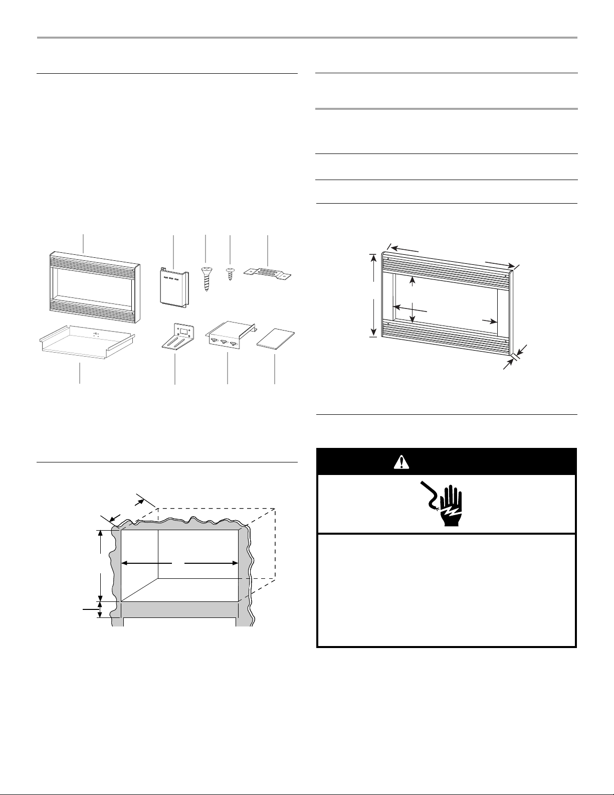
Parts Supplied
A B C D E
F G H I
A. Trim kit frame
B. Side duct (1)
C. 1" screws (4, plus 2 extra)
D. 1/2" screws (15, plus 2 extra)
E. Anti-tip bracket (1)
■ #2 Phillips screwdriver
■ 5/64" drill
F. Bottom duct (1)
G. Bottom bracket (1)
H. Upper duct (1)
I. Template
DIM. OVER 24"
(61.0 CM)
BUILT-IN OVEN
Width 22¹⁄₂"
(57.15 cm)
OVER 27"
(68.6 CM)
BUILT-IN OVEN
25¹⁄₂"
(64.77 cm)
OVER 30"
(76.2 CM)
BUILT-IN OVEN
25¹⁄₂"
(64.77 cm) min.;
28¹⁄₂"
(72.39 cm) max.
Depth 18¹⁄₂" (46.99 cm) min. with flush mount receptacle;
19" (48.26 cm) min. without flush mount receptacle
Height 15³⁄₄" (40.01 cm) (for all models)
Trim Kit Frame Dimensions
23
¹³⁄₁₆
" (60.5 cm)*
26
⁷⁄₈
" (68.3 cm)**
29
¹³⁄₁₆
" (75.7 cm)***
18¹⁄₄"
(46.4 cm)
12¹⁄₁₆"
(30.6 cm)
22
¹⁄₈
" (56.2 cm)
¹³⁄₁₆"
(2.1 cm)
*For installation over 24" (61.0 cm) built-in oven
**For installation over 27" (68.6 cm) built-in oven
***For installation over 30" (76.2 cm) built-in oven
Electrical Requirements
Minimum Cutout Dimensions
A
15³⁄₄"
(40.0 cm)
3"
(7.6 cm)
A. Depth
B. Width
WidthWidth
B
WARNING
Electrical Shock Hazard
Plug into a grounded 3 prong outlet.
Do not remove ground prong.
Do not use an adapter.
Do not use an extension cord.
Failure to follow these instructions can result in death,
fire, or electrical shock.
Observe all governing codes and ordinances.
Required:
■ A 120 Volt, 60 Hz, AC only, 15- or 20-amp electrical supply
with a fuse or circuit breaker.
2
Recommended:
A
■ A time-delay fuse or time-delay circuit breaker.
■ A separate circuit serving only this microwave oven.
GROUNDING INSTRUCTIONS
■
For all cord connected appliances:
The microwave oven must be grounded. In the event of
an electrical short circuit, grounding reduces the risk of
electric shock by providing an escape wire for the electric
current. The microwave oven is equipped with a cord
having a grounding wire with a grounding plug. The plug
must be plugged into an outlet that is properly installed
and grounded.
WARNING: Improper use of the grounding plug can
result in a risk of electric shock. Consult a qualified
electrician or serviceman if the grounding instructions are
not completely understood, or if doubt exists as to whether
the microwave oven is properly grounded.
Do not use an extension cord. If the power supply cord is
too short, have a qualified electrician or serviceman install
an outlet near the microwave oven.
SAVE THESE INSTRUCTIONS
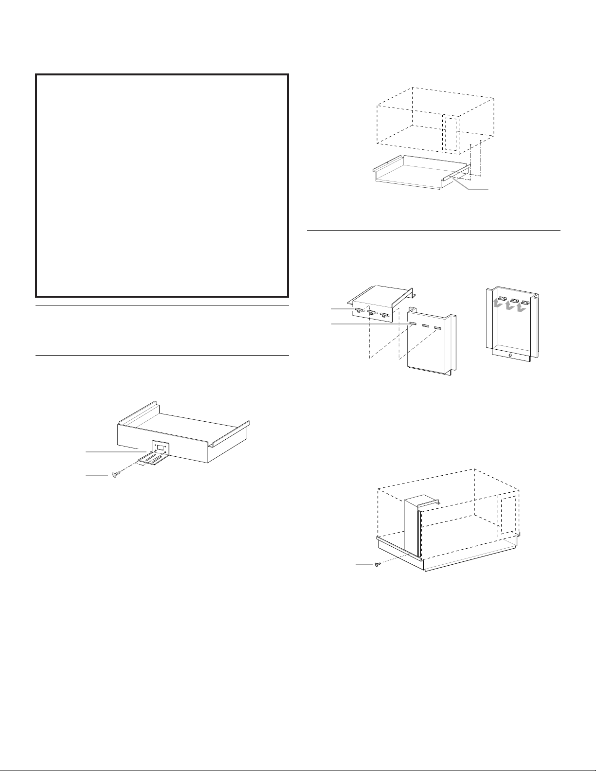
Microwave Oven Preparation
1. Unplug microwave oven before proceeding with installation.
2. Remove any loose items inside microwave oven.
2. Remove 2 existing screws from right side of microwave oven,
and 1 existing screw from left side.
3. Install bottom duct with 2 existing screws on right side of
oven.
(Front view of microwave oven)
A. Existing screws
Side Duct and Upper Duct Assembly
1. Connect side duct to upper duct:
Insert projecting tabs of upper duct into holes of side duct.
Then bend tabs upward.
A
B
Bottom Duct Assembly
1. Fasten bottom bracket to bottom duct using two ¹⁄₂" screws.
(Rear view of bottom duct)
A
B
A. Bottom bracket
B.
¹⁄₂
" screws
A. Tabs of upper duct
B. Holes in side duct
NOTE: Remove any dirt or oil on microwave oven surface before
ducts are attached.
2. Peel off backing of double-sided tape. Align the duct
assembly screw hole to the existing screw hole on left side of
microwave oven, and attach the duct assembly to the oven.
Press down firmly on ducts, then fasten with existing screw.
A
A. Existing screw
3
 Loading...