


MH9180XL
Whirlpool MH9180XL, GH9185XL, GH9185XLB, GH9185XLT, MH9180XLB Service Manual
...
CONSUMER SERVICES TECHNICAL
EDUCATION GROUP PRESENTS
MICROWAVE
HOOD COMBINATION
KM-28
Models GH9185XL & MH9180XL
JOB AID
Part No. 8178229

FORWARD
This Whirlpool Job Aid, “Microwave Hood Combination,” (Part No. 8178229), provides the
technician with information on the installation, operation, and service of the Microwave Hood
Combination. It is to be used as a training Job Aid and Service Manual.
The Wiring Diagram used in this Job Aid is typical and should be used for training purposes only.
Always use the Wiring Diagram supplied with the product when servicing the unit.
GOALS AND OBJECTIVES
The goal of this Job Aid is to provide detailed information that will enable the service technician to
properly diagnose malfunctions and repair the Microwave Hood Combination.
The objectives of this Job Aid are to:
• Understand and follow proper safety precautions.
• Successfully troubleshoot and diagnose malfunctions.
• Successfully perform necessary repairs.
• Successfully return the Microwave Hood Combination to its proper operational status.
WHIRLPOOL CORPORATION assumes no responsibility for any repairs made
on our products by anyone other than Authorized Service Technicians.
Copyright © 2002, Whirlpool Corporation, Benton Harbor, MI 49022
- ii -

TABLE OF CONTENTS
Page
GENERAL............................................................................................................................... 1-1
Important Safety Information ............................................................................................. 1-1
Warning To Service Technicians ....................................................................................... 1-4
Precautions To Be Observed Before And During Servicing
To Avoid Possible Exposure To Excessive Microwave Energy ..................................... 1-5
R.F. Leakage Test ............................................................................................................. 1-6
Precautions To Be Observed When Troubleshooting ....................................................... 1-7
Model & Serial Number Designations ................................................................................ 1-8
Model & Serial Number Label And Tech Sheet Locations................................................. 1-9
Specifications................................................................................................................... 1-10
Whirlpool Microwave Oven Warranty .............................................................................. 1-12
INSTALLATION INFORMATION ........................................................................................... 2-1
Microwave Height & Weight Variations.............................................................................. 2-1
Adjusting The Exhaust Airflow ........................................................................................... 2-2
Removing & Reinstalling The Microwave Oven................................................................. 2-3
THEORY OF OPERATION ..................................................................................................... 3-1
Microwave Operation ......................................................................................................... 3-1
COMPONENT ACCESS ......................................................................................................... 4-1
Component Locations ........................................................................................................ 4-1
Removing The Cabinet ...................................................................................................... 4-2
Removing The Bottom Cover & Hood Lamp Socket ......................................................... 4-3
Removing Cavity Thermostat 1 & The Humidity Sensor ................................................... 4-4
Removing The Stirrer Motor .............................................................................................. 4-6
Removing Cavity Thermostats 2 & 3 ................................................................................. 4-8
Removing The Hood Exhaust Fan Motor ........................................................................ 4-10
Removing The Cavity Lamp & Socket ............................................................................. 4-11
Removing The Control Panel Assembly, The Power Supply
& Display Boards, And The Keyboard .......................................................................... 4-12
Removing An Inline Fuse................................................................................................. 4-14
Removing The AC Line Filter Capacitor .......................................................................... 4-15
Removing The Cooling Fan Motor, The Exhaust Fan Thermostat,
And The Line Fuseholder ............................................................................................. 4-16
Removing The Exhaust Motor Start Capacitor, The Magnetron
Thermostat, & The 40 W Inverter Board ....................................................................... 4-18
Removing The 1100 W Inverter Board ............................................................................ 4-20
Removing The Magnetron ............................................................................................... 4-22
Removing The Primary & Secondary Interlock Switches,
And The Monitor Switch................................................................................................ 4-24
Removing The Turntable Motor ....................................................................................... 4-26
Removing The Oven Door And The Inner Panel ............................................................. 4-27
- iii -

COMPONENT TESTING ........................................................................................................ 5-1
Door Switches.................................................................................................................... 5-1
Touch Panel Continuity...................................................................................................... 5-2
Stirrer & Turntable Motors ................................................................................................. 5-3
AC Line Filter Capacitor..................................................................................................... 5-3
Humidity Sensor ................................................................................................................ 5-4
Cavity Thermostats 1, 2, & 3 ............................................................................................. 5-4
Line Fuse & Exhaust Fan Thermostat ............................................................................... 5-5
Exhaust Motor Start Capacitor........................................................................................... 5-5
Cooling Fan Motor ............................................................................................................. 5-6
Hood Exhaust Fan Motor ................................................................................................... 5-6
Magnetron.......................................................................................................................... 5-7
Magnetron Thermostat ...................................................................................................... 5-7
Inverters ............................................................................................................................. 5-8
DIAGNOSIS & TROUBLESHOOTING ................................................................................... 6-1
Power Output Measurement .............................................................................................. 6-1
Failure Codes .................................................................................................................... 6-1
Display And Power Board Callouts .................................................................................... 6-2
Primary, Secondary, & Monitor Switch Checks ................................................................. 6-3
Touch Panel & Microcomputer Board Test ........................................................................ 6-4
WIRING DIAGRAMS & STRIP CIRCUITS ............................................................................. 7-1
Schematic Diagram ........................................................................................................... 7-1
Wiring Diagram .................................................................................................................. 7-2
Strip Circuits ...................................................................................................................... 7-3
- iv -
GENERAL
IMPORTANT SAFETY INFORMATION
Your safety and the safety of others is very important.
We have provided many important safety messages in this Job Aid and on the appliance. Always
read and obey all safety messages.
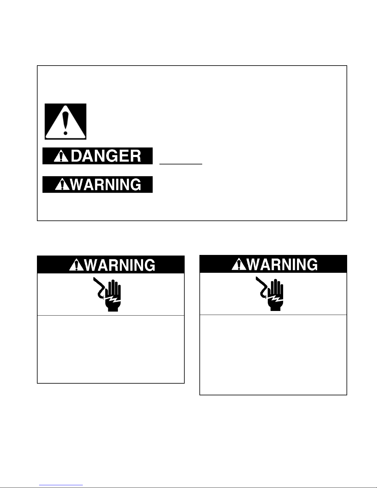
This is the safety alert symbol.
This symbol alerts you to hazards that can kill or hurt you and others.
All safety messages will follow the safety alert symbol and either the word
“DANGER” or “WARNING.” These words mean:
You can be killed or seriously injured if you don’t
immediately follow instructions.
You can be killed or seriously injured if you don’t
follow instructions.
All safety messages will tell you what the potential hazard is, tell you how to reduce the
chance of injury, and tell you what can happen if the instructions are not followed.
ELECTRICAL POWER SUPPLY &
GROUNDING REQUIREMENTS
Electrical Shock Hazard
Disconnect power before servicing.
Replace all parts and panels before
operating.
Failure to do so can result in death or
electrical shock.
Electrical Shock Hazard
Plug into a grounded 3-prong outlet.
Do not remove ground prong.
Do not use an adapter.
Do not use an extension cord.
Failure to follow these instructions can
result in death, fire, or electrical shock.
1-1
For continued protection against radiation
emission, replace only with these types of
switches: Primary (Interlock) Switch: SZM-V16FA-63 or VP-533A-OF; Secondary (Interlock)
Switch: SZM-V01-FA-32; Interlock (Monitor)
Switch: SZM-VI6-FA-62 or VP-532A-OF; Oven
Lamp Switch: SZM-V6-FA-31 or VP-331 A-OD.
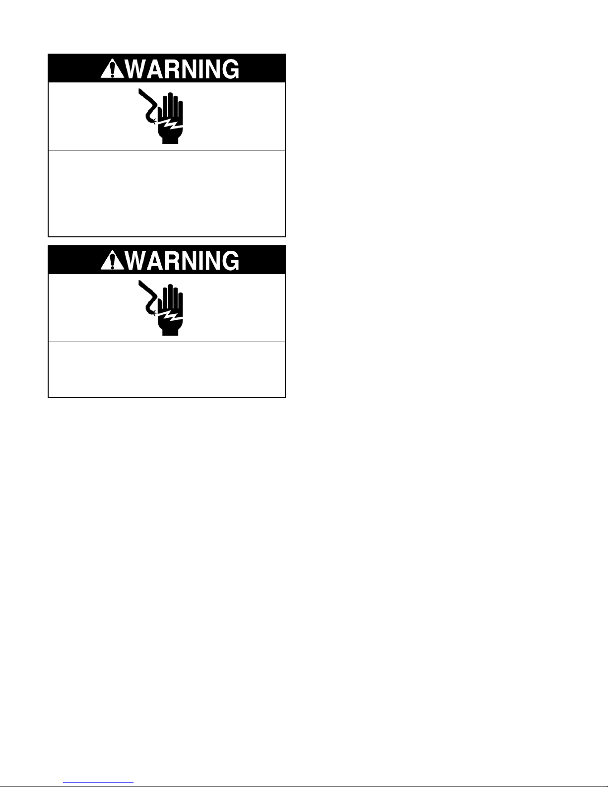
Electrical Shock Hazard
Connect green ground wire to ground
screw.
Failure to do so can result in death or
electrical shock.
Electrical Shock Hazard
Improper use of the grounding plug can
result in a risk of electrical shock.
Before touching any oven component or wiring, always unplug the oven from its power
source and discharge the 1100 Watt inverter
(see page 4-20).
Check that the unit is grounded before troubleshooting. Be careful of the high voltage circuits.
Discharge any static charge from your body by
touching ground before handling any part of
the circuitry on the control board. Electrostatic
discharge may damage the control circuit.
It is neither necessary nor advisable to attempt
measurement of high voltage.
Attaching the adaptor ground terminal to the
wall receptacle cover screw does not ground
the appliance unless the cover screw is metal
and not insulated and the wall receptacle is
grounded through the house wiring.
The microwave oven must be grounded. In the
event of an electrical short circuit, grounding
reduces the risk of electrical shock by providing
an escape wire for the electrical current. The
microwave oven is equipped with a cord having
a grounding wire with a grounding plug. The
plug must be plugged into an outlet that is
properly installed and grounded.
Consult a qualified electrician or serviceman if
the grounding instructions are not completely
understood, or if doubt exists as to whether the
microwave oven is properly grounded. Do not
use an extension cord. If the power supply cord
is too short, have a qualified electrician or
serviceman install an outlet near the microwave oven.
Do not touch oven components or wiring during
operation. Attach meter leads with alligator
clips when making operational tests.
1-2

ELECTROSTATIC DISCHARGE
(ESD) SENSITIVE ELECTRONICS
ESD problems are present everywhere. ESD
may damage or weaken the electronic control
assembly. The new control assembly may appear to work well after repair is finished, but
failure may occur at a later date due to ESD
stress.
• Use an antistatic wrist strap. Connect the
wrist strap to a green ground connection
point or unpainted metal in the appliance; or
touch your finger repeatedly to a green ground
connection point or unpainted metal in the
appliance.
• Before removing the part from its package,
touch the antistatic bag to a green ground
connection point or unpainted metal in the
appliance.
• Avoid touching electronic parts or terminal
contacts. Handle the electronic control assembly by the edges only.
• When repackaging the failed electronic control assembly in an antistatic bag, observe
the above instructions.
1-3

WARNING TO SERVICE TECHNICIANS
To avoid possible exposure to microwave radiation or energy, visually check the oven for
damage to the door and door seal before
operating any oven. Use a microwave survey
meter to check the amount of leakage before
servicing. In the event the R.F. Ieakage exceeds 4 mw/cm2 at 5 cm, appropriate repair
must be made before continuing to service the
unit. Check interlock function by operating the
door latch. The oven cook cycle should cut off
before the door can be opened.
The door and latching assembly contains the
radio frequency energy within the oven. The
door is protected by three safety interlock
switches. Do not attempt to defeat them.
Under no circumstances should you try to
operate the oven with the door open.
• Proper operation of microwave ovens requires that the magnetron be properly
assembled to the waveguide and cavity.
Never operate the magnetron unless it is
properly installed.
• Be sure the “RF” seal is not damaged and
is assembled around the magnetron dome
properly when installing the magnetron.
• Routine service safety procedures should
be exercised at all times.
• Untrained personnel should not attempt
service without a thorough review of test
procedures and safety information contained in this Job Aid.
Whirlpool microwave ovens have a monitoring
system designed to assure proper operation of
the safety interlock systems.
The monitor switch will immediately cause the
oven fuse to blow if the door is opened and the
primary door interlock switch and/or the secondary interlock switch contacts fail in a closed
position.
CAUTION: Replace a blown fuse with a 20
ampere class H fuse only.
Test the upper and lower door interlock
switches, cook relay, and monitor switch (middle
switch) for proper operation as described in the
component test procedures, before replacing
the blown oven fuse.
Do not attempt to repair sticking contacts
of any interlock switch, safety switch, or
Cook (Latch) relay. The components must
be replaced.
Any indication of sticking contacts during component tests requires replacement of that component to assure reliability of the safety interlock system.
If the fuse is blown, the Monitor switch, and
the Primary, and Secondary interlock
switches must be replaced. Be sure they
are properly connected.
1-4

PRECAUTIONS TO BE OBSERVED BEFORE AND DURING
SERVICING TO AVOID POSSIBLE EXPOSURE
TO EXCESSIVE MICROWAVE ENERGY
A. Do not operate or allow the oven to be
operated with the door open.
B. Make the following safety checks on all
ovens to be serviced before activating the
magnetron or other microwave source,
and make repairs as necessary:
1)Interlock Operation
2)Proper Door Closing
3)Seal and Sealing Surfaces (Arcing,
Wear, and Other Damage)
4)Damage to or Loosening of Hinges and
Latches
5) Evidence of Dropping or Abuse
C. Before turning on the microwave power
for any service test or inspection within the
microwave generating components, check
the magnetron, wave guide or transmission line, and cavity for proper alignment,
integrity, and connections.
D. Any defective or misadjusted components
in the interlock, monitor, door seal, and
microwave generation and transmission
systems shall be repaired, replaced, or
adjusted, using procedures described in
this Job Aid, before the oven is released to
the owner.
E. A microwave leakage check to verify com-
pliance with the Federal Performance Standard should be performed on each oven
prior to release to the owner.
F. Do not attempt to operate the oven if the
door glass is broken.
1-5

R.F. LEAKAGE TEST
EQUIPMENT
• Electromagnetic energy leakage monitor
(NARDA 8100B, HOLADAY H 1501 ).
• 275 ±15 ML glass beaker.
TEST
On every service call, checks for microwave
energy emission must be made according to
the following manner.
1. Remove the cooking rack from the oven
cavity, if the microwave oven is so
equipped.
2. Place a 275 ±15 ML (9.3 oz.) glass of
water in the center of the oven bottom.
3. Select "HIGH" cook power, turn the micro-
wave oven on, and test for R.F. Ieakage at
the following locations:
a)Around the cabinet at the front.
b)Around the door.
c) Across the console panel.
d)Horizontally across the door.
e)Vertically across the door.
f) Diagonally across the door.
g)Across the air vents.
h)Across the rear air vent.
i) All lockseams.
j) Weld at bottom.
k) Bottom plate.
I) Oven feet.
4. The scan speed is one inch per second.
When checking for R.F. Ieakage, use an approved R.F. measuring device to assure less
than 4 mw/cm2 emission at 5 cm distance with
a maximum scan rate of 2.54 cm/second, in
compliance with U.S. Government Department
of Health, Education and Welfare 21CFR1030,
Performance Standard for Microwave Ovens.
NOTE: Enter leakage readings in space BEFORE and AFTER on the service document.
All microwave ovens exceeding the emission
level of 4 mw/cm2 must be reported to Dept. of
Service for Microwave Ovens immediately and
the owner should be told not to use the microwave oven until it has been repaired completely.
If a microwave oven is found to operate with the
door open, report to Dept. of Service, the
manufacturer and CDRH* immediately. Also
tell the owner not to use the oven.
The monitor switch acts as the final safety
switch protecting the customer from microwave radiation. If the monitor switch operated
to blow the fuse when the interlocks failed, you
must replace all interlock switches with new
ones, because the contacts of those interlock
switches may be melted and welded together.
If safety interlock/monitor switch replacement,
or adjustment, is required, you must reconnect
the circuit, and perform a continuity check on
the monitor circuit.
All repairs must be performed in such a manner
that microwave energy emissions are minimal.
Address for CDRH is:
Office of Compliance (HFZ-312) Center for
Devices and Radiological Health
1390 Piccard Drive
Rockville, MD 20850
* CDRH: Center for Devices and Radiological Health,
Food and Drug Administration.
A properly operating door and seal assembly
will normally register small emissions, but they
must be no greater than 4 mw/cm2 to allow for
measurement uncertainty.
1-6

PRECAUTIONS TO BE OBSERVED WHEN TROUBLESHOOTING
The microwave oven is a high voltage, high
current appliance. It is free from danger during
ordinary use, but extreme care should be taken
during repair.
VOLTAGE CAPACITORS
WARNING
DISCHARGING HIGH
CAUTION
Service technicians should remove their
watches whenever working close to or replacing the magnetron.
DANGER
HIGH VOLTAGE AND HIGH TEMPERA-
TURE (HOT/LIVE) OF THE INVERTER
POWER SUPPLY
The high voltage inverter power supply circuit supplies very high voltage and very high
current for the magnetron tube. Though it is
free from danger in ordinary use, extreme
care should be taken during repair. The
current is extremely large, and so danger
exists because of its high current and high
voltages.
The aluminum heat sink is also energized
with high voltage (HOT), so do not touch it
when the AC input terminal is connected to
the power line. One of the IGBT switching
power devices (collector) is directly connected to the aluminum heat sink.
The aluminum heat sink may be HOT from
heat energy; therefore, extreme care should
be taken during servicing and replacing.
For about 30 seconds after the oven is
turned off, an electric charge remains in the
high voltage capacitors in the inverter power
supply circuit board.
When replacing or checking parts, remove
the power plug from the outlet. Use a screwdriver with an insulated handle, and short the
inverter output of the magnetron filament
terminals to discharge it. Be sure to touch the
chassis ground side first, and then touch the
output terminals.
WARNING
There is high voltage present, with high
current capabilities in the circuits of the primary and secondary windings, the choke
coil, and the heat sink of the inverter. It is
extremely dangerous to work on or near
these circuits with the microwave oven energized. DO NOT measure the voltage in the
high voltage circuit, including the filament
voltage of the magnetron.
WARNING
Never touch any circuit wiring with your
hand, or with an insulated tool during operation.
WARNING
INVERTER POWER
SUPPLY GROUNDING
Check the high voltage inverter power supply circuit grounding. This high voltage inverter power supply circuit board must have
a proper chassis ground by the grounding
bracket to the chassis ground; otherwise,
this H.V. inverter circuit board will expose
very high voltage, and cause extreme DANGER. Be sure to have proper grounding by
the grounding plate and screws.
WARNING
Never insert a wire, nail, or any other metal
object through the lamp holes on the cavity,
or any other holes or gaps. Doing so may act
as an antenna, and cause microwave leakage.
WARNING
Before touching any oven components or
wiring, always unplug the oven from its
power source, and discharge the capacitors in the high voltage inverter.
1-7

MODEL & SERIAL NUMBER DESIGNATIONS
MODEL NUMBER
MODEL NUMBER G H 9 18 5 X L B 0
INTERNATIONAL SALES IND.
OR MARKETING CHANNEL
IF PRESENT
PRODUCT GROUP
G = WHIRLPOOL GOLD
M = MICROWAVE
PRODUCT IDENTIFICATION
B = BROWNER
C = CONVECTION
G = GRILL / CRISPER
H = OTR HOOD COMBO
K = KITS
M = GOLD CONVECTION
S = STIRRER FAN
T = TURNTABLE
MODEL VARIATIONS
0 - 9
CUBIC FEET
04 = .4 CU. FT. 10 = 1.0 CU. FT.
06 = .6 CU. FT. 12 = 1.2 CU. FT.
07 = .7 CU. FT. 14 = 1.4 CU. FT.
08 = .8 CU. FT. 15 = 1.5 CU. FT.
09 = .9 CU. FT. 18 = 1.8 CU. FT.
FEATURE LEVEL
0 = 30˝ KIT (IF KIT)
2 = 22˝ KIT (IF KIT)
4 = 24˝ KIT (IF KIT)
5 = SENSORED MODEL
7 = 27˝ KIT (IF KIT)
FEATURE CODE
C = CSA APPROVED
S = CARRY IN WARRANTY (EFFECTIVE 02/96)
X = IN HOME WARRANTY (EFFECTIVE O2/96)
YEAR OF INTRODUCTION
J = 2000, K = 2001, L = 2002
COLOR CODE
B = BLACK, Q = WHITE, T = BISCUIT
ENGINEERING CHANGE (0, 1, 2, ETC.)
SERIAL NUMBER
SERIAL NUMBER XC L 3 8 10006
MANUFACTURING SITE
XC = SHUNDE - CHINA
YEAR OF PRODUCTION
L = 2001, M = 2002
WEEK OF PRODUCTION
38TH WEEK
PRODUCT SEQUENCE NUMBER
1-8
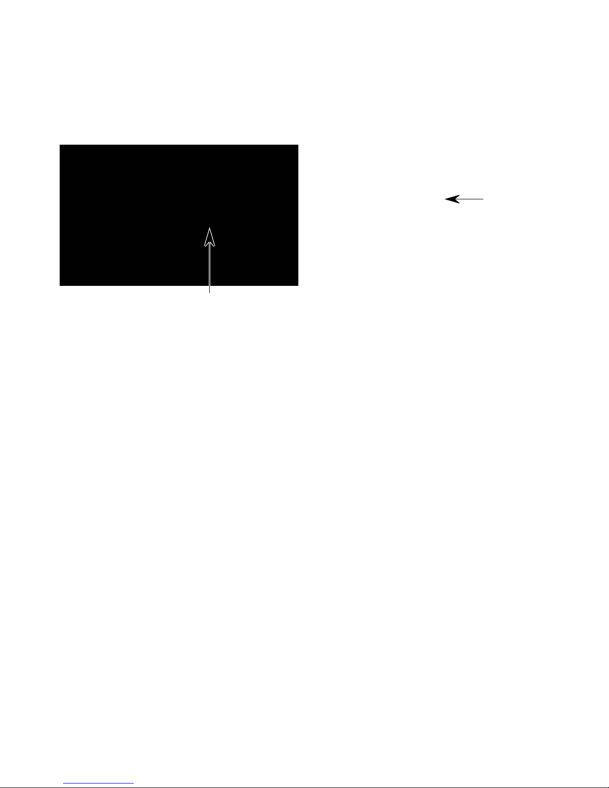
MODEL & SERIAL NUMBER LABEL
AND TECH SHEET LOCATIONS
The Model/Serial Number label and Tech Sheet locations are shown below.
Model & Serial
Number Label Location
Tech Sheet
Location
(Behind Grille)
1-9
SPECIFICATIONS
MODEL GH9185XL/B/T MH9180XL/B/T
CONTROL SYSTEM Sensor Non-Sensor
Timer Yes Yes
Type Electronic Electronic
Limits 99 Min. 99 Sec. 99 Min. 99 Sec.
Scale Linear (Digital) Linear (Digital)
Operation TOUCH CONTROL, 31 Pads TOUCH CONTROL, 29 Pads
2 Line Display with Multicolor Progress Bar 2 Line Display with Multicolor Progress Bar
Display
MICROWAVE COOKING CYCLES
Cook Time Yes Yes
Auto Reheat (Sensored & Non-Sensored) Yes - 5 Categories Yes - 5 Categories
Auto Defrost (Non-Sensored) Yes - 3 Categories By Weight Yes - 3 Categories By Weight
Auto Cook (Sensored & Non-Sensored) Yes - 7 Categories Yes - 7 Categories
Warm Hold 10% Power - 99 Min. 99 Sec. Max. 10% Power - 99 Min. 99 Sec. Max.
Jet Start Yes, 30 Sec Yes, 30 Sec
OTHER FEATURES
Pause Door Open Door Open
Clock Yes Yes
Independent Minute Timer: Yes Yes
Timer Set Yes Yes
Timer Off Yes Yes
Stage Cooking Yes (3) Yes (3)
In-Use Reprogramming Yes Yes
More/Less Function Yes - Hidden "Cook Power" Button Yes - Hidden "Cook Power" Button
Keypad Disable / Child Lockout Mode Yes - Press "Enter" Key for 5 Seconds Yes - Press "Enter" Key for 5 Seconds
Type Electronic Electronic
Range 0% - 100% 0% - 100%
Scale Digital Digital
Levels Ten Ten
Operation Direct Entry Direct Entry
Exhaust Fan Yes - One Key Operation Yes - One Key Operation
Number of Speeds 4 4
Automatic Turn On 60° C, 140°F60° C, 140°F
Cooktop Light / Settings Halogen/ 3 Levels Incadescent/ 3 Levels
Light "ON" When Cook Cycle Complete Yes No
Technical Error Indication "F-" With Error Number "F-" With Error Number
Diagnostic System Yes Yes
5+2 Digit - Blue-Green 5+2 Digit - Blue-Green
Fluorescent - Callouts In Display Fluorescent - Callouts In Display
1-10
MODEL GH9185XL/B/T MH9180XL/B/T
OVEN INTERIOR FEATURES
Size (inches) 22 7/8" W x 9 1/2" H x 14 1/2" D 22 7/8" W x 9 1/2" H x 14 1/2" D
Capacity 1.8 Cubic Feet 1.8 Cubic Feet
Cooking Power 1100 Watts (IEC-705 Rating) 1100 Watts (IEC-705 Rating)
Turntable Yes, Sunken Flush Yes, Sunken Flush
Glass turntable diameter 12" 12"
Ventilation Axial blower Axial blower
Cooling Fan
Light
DOOR FEATURES
Seals
MICROWAVE SYSTEM
Distribution Top Feed with Stirrer Top Feed with Stirrer
Magnetron Inverter Type Inverter Type
SAFETY FEATURES
Interlock
Thermal Protectors Five - 1 Magnetron, 3 Oven Cavity, 1 Hood Five - 1 Magnetron, 3 Oven Cavity, 1 Hood
VENTILATION SYSTEM
Type
Duct Outlet Size 3 1/4"H x 10"W 3 1/4"H x 10"W
Recirculation CFM 130 130
Exhaust CFM 175 17 5
Touch Control 4 Speed 2 Speed
Auto ON - High Speed Yes, 60°C, 140°F Yes, 60°C, 140°F
Noise Level Recirculation (Acc. to IEC 704) 67dBA 67dBA
Shipped Recirculation mode Recirculation mode
EXTERIOR FEATURES
Outside Dimensions (mm) 760 mm x 438 mm x 392 mm 760 mm x 438 mm x 392 mm
Outside Dimensions (in) 30" W x 17 1/4" H x 15 7/16" D 30" W x 17 1/4" H x 15 7/16" D
Power Cord Length 3 Feet 3 Feet
OTHER SPECIFICATIONS
Automatic - On if oven is operating,
Off if door open
30 Watt, Automatic - Turns on when oven
door is open or oven is operating.
Two Stage Two Stage
(Capacitive and Reflective) (Capacitive and Reflective)
Three Door/Latch Operated Three Door/Latch Operated
Primary, secondary and monitor Primary, secondary and monitor
Convertible Recirculation or Exhaust
Vertical/Horizontal
Automatic - On if oven is operating,
Off if door open
30 Watt, Automatic - Turns on when oven
door is open or oven is operating.
Convertible Recirculation or Exhaust
Vertical/Horizontal
Electrical
Agency Approvals FCC, DHHS, U.L. Listed, CSA FCC, DHHS, U.L. Listed, CSA
Approx. Shipping Weight - Lb 86 86
Approx. Net Weight - Lb 7 9 7 9
APPROVED ACCESSORIES
Tupperware Steam Cook Vessel Yes (Included) No
Exhaust Damper Assembly Yes (1 Set) Yes (1 Set)
Hardware for Installation Yes (1 Set) Yes (1 Set)
LITERATURE
Use & Care Guide 8183957 8183958
Cooking Guide Yes Yes
Installation Instructions 8184059 8184059
Warranty
Tech Sheet 8184635 8184634
Service Manual 8178229 8178229
120V, Single Phase, 60 Hz 1800 Watts,
For Use With 15 - 20 Amp Circuit
In Use & Care Guide-1 Yr.
Full, 2-5 Yr. Ltd. Mag. Tube
1-11
120V, Single Phase, 60 Hz 1800 Watts,
For Use With 15 - 20 Amp Circuit
In Use & Care Guide-1 Yr.
Full, 2-5 Yr. Ltd. Mag. Tube

WHIRLPOOL MICROWAVE OVEN WARRANTY
LENGTH OF
WARRANTY:
ONE-YEAR FULL
WARRANTY
From Date of
Purchase.
LIMITED FOURYEAR WARRANTY Second
through fifth year
from Date of
Purchase.
WHIRLPOOL
WILL PAY FOR:
FSP ® Replacement parts and
repair labor costs
to correct defects
in materials or
workmanship.
Service must be
provided by a
Whirlpool-designated servicing
company.
FSP ® Replacement magnetron
tube on microwave
ovens if defective
in materials or
workmanship.
WHIRLPOOL
WILL NOT PAY FOR:
A. Service calls to:
1. Correct the installation of the microwave
oven.
2. Instruct you how to use the microwave
oven.
3. Replace house fuses or correct house
wiring.
4. Replace owner-accessible light bulbs.
B. Repairs when microwave oven is used in
other than normal single-family household
use.
C. Pickup and delivery. The microwave is de-
signed to be repaired in the home.
D. Damage to the microwave oven resulting
from accident, alteration, misuse, abuse, fire,
flood, acts of God, or use of products not
approved by Whirlpool Corporation.
E. Any labor costs during the limited warranty.
F. Repairs to parts or systems resulting from
unauthorized modifications made to the
appliance.
G. Replacement parts or repair labor costs for
units operated outside the United States.
WHIRLPOOL CORPORATION SHALL NOT BE LIABLE FOR INCIDENTAL OR CONSEQUENTIAL DAMAGES. Some states do not allow the exclusion or limitation of incidental or
consequential damages, so this exclusion or limitation may not apply to you. This warranty
gives you specific legal rights, and you may also have other rights which vary from state to
state.
Outside the United States, this warranty does not apply. Contact your authorized Whirlpool dealer to determine if another warranty applies.
If you need service, see the “Assistance or Service” section in the Use & Care Guide, or by
calling our Customer Interaction Center telephone number, 1-800-253-1301, from anywhere in
the U.S.A.
1-12

INSTALLATION INFORMATION
MICROWAVE HEIGHT & WEIGHT VARIATIONS
Due to a height variation between microwave
units, the new Microwave Hood Combination
uses a mounting plate that is different from
earlier-designed microwave hood combinations. The new Microwave Hood Combination
measures 17-1/8″ in height, while earlier-de-
Earlier-Designed Microwave Hood Combination
signed microwave units measure 16-1/4″. Because of this height difference, the microwave
hood mounting plates are not interchangeable.
The new Microwave Hood Combination also
weighs considerably less than standard microwave ovens: 49 lbs. versus 86 lbs.
New Microwave Hood Combination
17-1/8″ High/ 49 lbs.
16-1/4″ High / 86 lbs.
2-1
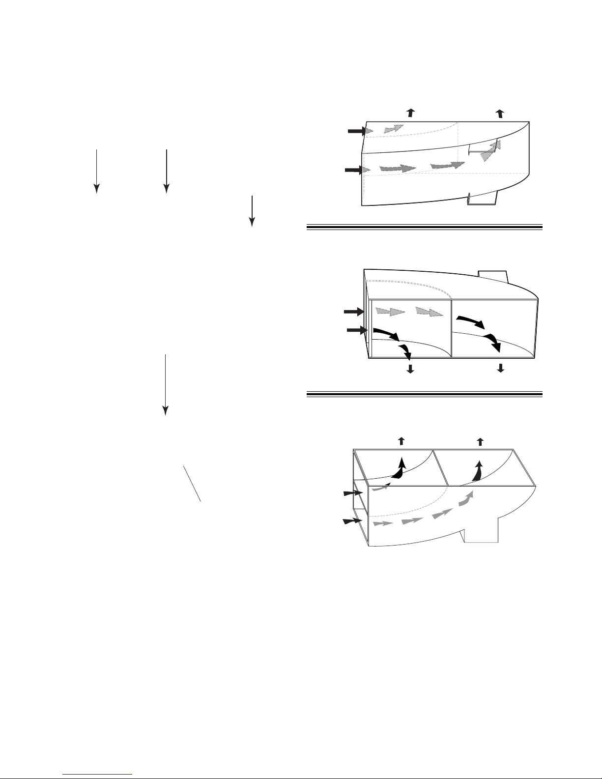
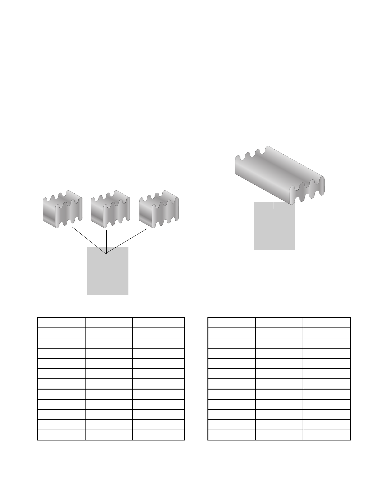
ADJUSTING THE EXHAUST AIRFLOW
1. Remove the screw from the damper plate
on top of the microwave cabinet, and
remove the plate from under the cabinet
flanges.
Flange
Damper Plate
Screw
2. Slide the air deflector out of the cabinet.
Air Deflector
Recirculating Air
Toward Front Of Unit
Blower Air Inlet
Rear Venting
Blower Air Inlet
3. Refer to the following illustrations and
determine how you would like to direct the
exhaust air out of the microwave oven.
NOTE: All microwave ovens are shipped
with the venting in the “recirculating” mode.
Toward Rear Of Unit
Top Venting
Toward Top Of Unit
Blower Air Inlet
4. Rotate the air deflector so that the vanes
face in the desired direction, and slide the
air deflector back into the cabinet as far as
it will go, then reinstall the damper plate.
2-2
REMOVING & REINSTALLING THE MICROWAVE OVEN
To remove the microwave oven:
1. Unplug the microwave oven or disconnect
the power.
2. Open the microwave oven door.
3. Pull the top of the air grille forward to
release the clips, then lift the grille, and
remove the bottom tabs from the cabinet
slots.
Pull Top Of Air Grille Forward
4. Remove the turntable and roller assembly.
5. Tape the door closed.
CAUTION: Use two people to support the
microwave oven when you remove it from
its mounting location.
6. Remove the two bolts that secure the
microwave oven to the upper cabinet.
7. Hold the microwave oven in place with one
hand, and pull the latching arm forward to
release the latch from the rear mounting
plate clip.
Pull Latching Arm
Clip On Rear Mounting Plate
Latch Engaged
2-3
Latch Released
Continued on the next page.

8. Rotate the microwave oven downward,
and lift the oven to unhook it from the
bottom of the mounting plate. Set the oven
on a protected surface.
Mounting Plate Hook
To reinstall the microwave oven:
1. Carefully lift the microwave oven and hang
it on the mounting plate hooks.
2. Rotate the front of the microwave oven
cabinet downward and insert the power
supply cord through the hole in the bottom
of the cabinet.
3. Rotate the microwave oven towards the
cabinet and push the oven against the
mounting plate until the clip snaps into the
cabinet.
4. Install the two bolts that secure the microwave oven to the upper cabinet.
Rotate Down
5. Install the air grille.
6. Remove the tape from the door and replace the turntable and roller assembly.
7. Plug in the microwave oven.
2-4
THEORY OF OPERATION
MICROWAVE OPERATION
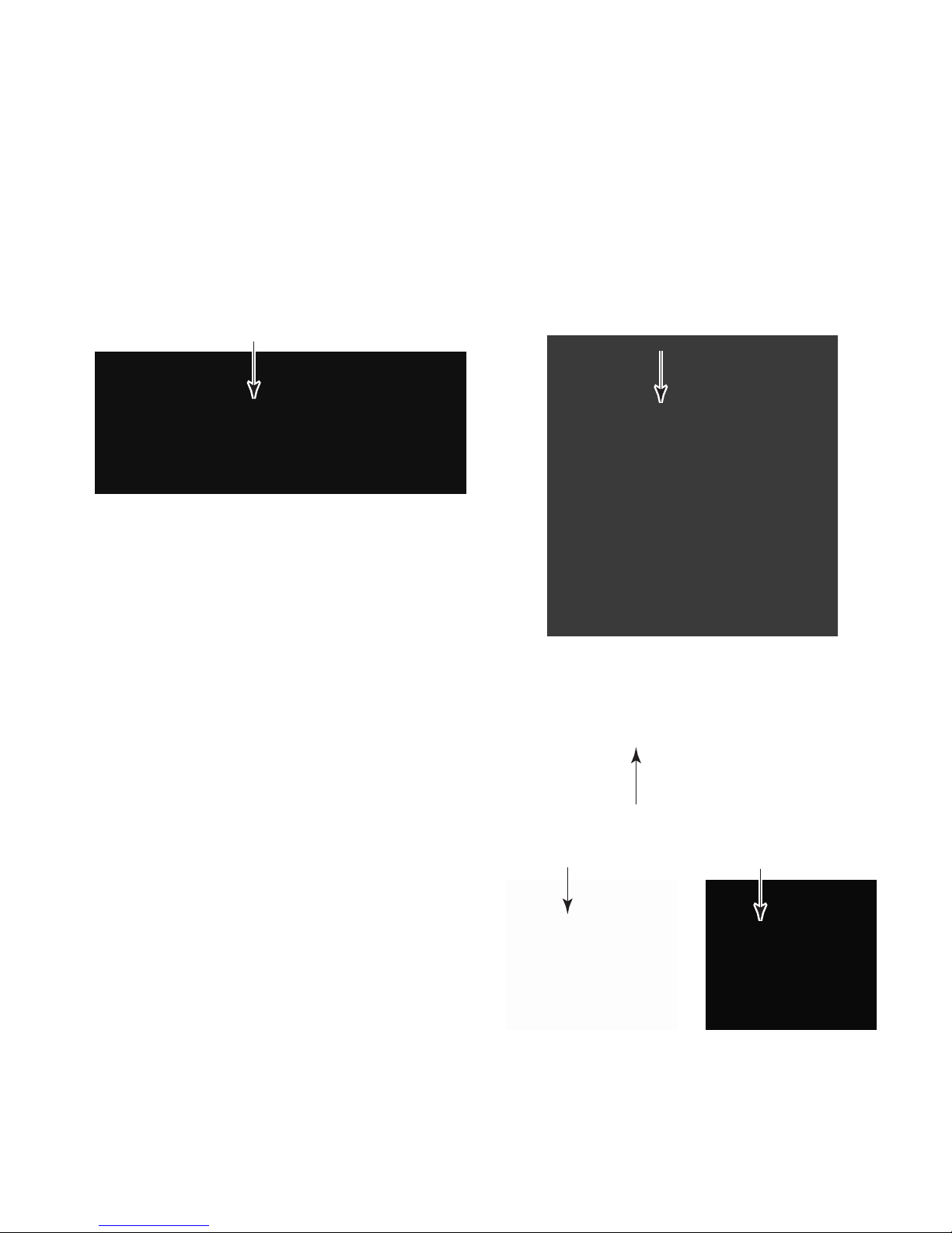
Traditional microwave technology is only able
to generate microwave energy at full power. In
order to reduce the power when cooking, defrosting, or reheating food, the microwave cycles
on and off, intermittently heating the food at full
power, so that the food is still heated with fullpower, but for less time. This makes it difficult
to achieve slow, or simmer-type cooking.
A microwave operates at full power whenever
the magnetron is on. Reducing the power level
only reduces the time that the magnetron is on.
50% Power Cycling On & Off
(Old Technology)
Newest developed technology has the ability
to control the level of microwave energy. When
cooking, defrosting, or reheating at reduced
power levels, the food receives constant energy that is evenly dispensed, producing true
slow, or simmer-type cooking.
50% Power On Continuously
(New Technology)
Old Technology New Technology
Power Level Magnetron On Magnetron Off Power Level Magnetron On Magnetron Off
0 0 Seconds 24 Seconds 0 0 Seconds 24 Seconds
1 4 Seconds 20 Seconds 1 24 Seconds 0 Seconds
2 6 Seconds 18 Seconds 2 24 Seconds 0 Seconds
3 8 Seconds 16 Seconds 3 24 Seconds 0 Seconds
4 11 Seconds 13 Seconds 4 24 Seconds 0 Seconds
5 13 Seconds 11 Seconds 5 24 Seconds 0 Seconds
6 16 Seconds 8 Seconds 6 24 Seconds 0 Seconds
7 18 Seconds 6 Seconds 7 24 Seconds 0 Seconds
8 20 Seconds 4 Seconds 8 24 Seconds 0 Seconds
9 22 Seconds 2 Seconds 9 24 Seconds 0 Seconds
10 24 Seconds 0 Seconds 10 24 Seconds 0 Seconds
3-1
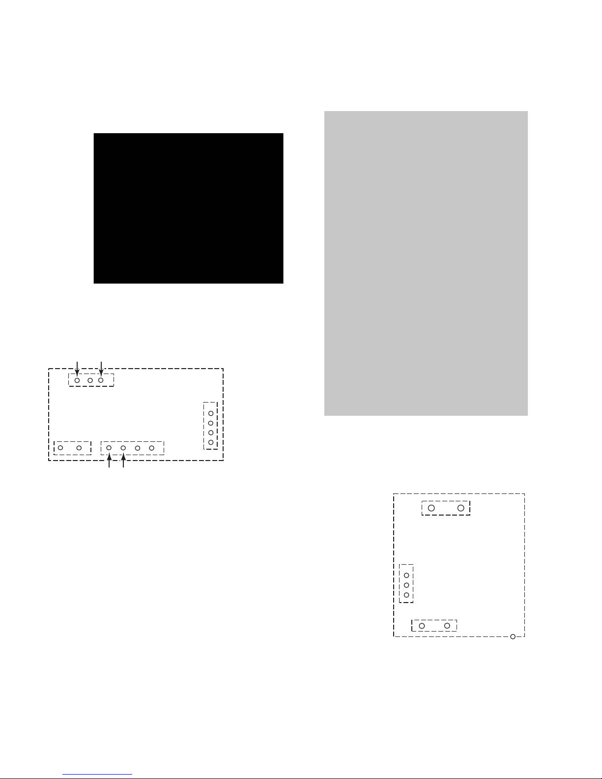
The power for the new Microwave Hood Combination is produced by 40 Watt and 1100 Watt
inverters.
The 40 Watt inverter provides 12 volts DC to
operate the cooling fan and cavity lights.
40 W INVERTER
(Supplies 12 VDC To
Cooling Fan & Cavity Lights)
The 1100 Watt inverter replaces the high voltage transformer, capacitor, and diode to provide the necessary power to operate the magnetron.
120 VAC Input
1
CN1
40 W INVERTER
CN152CN153
1
To Cooling
Fan Motor
To Hood Lamp
40 W INVERTER CONNECTORS
CN151
1
1
Logic Circuit
To P3 On
Control Board
1100 W INVERTER
(Replaces The High Voltage
Transformer, Capacitor, & Diode)
120 VAC Input
CN702
1100 W INVERTER
Logic Circuit
To P2 Connector
On Control Board
1
CN701
CN703
E701
3-2
Voltage Output
To Magnetron
To Ground
1100 W INVERTER CONNECTORS
 Loading...