

Whirlpool MH6701XW0 Installation Instructions Manual
IMPORTANT:
Installer: Leave lnstollation Instructions with
the Homeowner.
Homeowner: Keep Installation Instructions
for future reference.
Save lnstallotlon Instructions for local
electrical inspector’s use.
fih;fi7wave
Hood Combination
Before you start.. .
Proper installation Is the Installer’s
responsibility. A qualified technician
should install this microwave oven. Make
sure you have everything necessary for
correct installation. It Is the responsibility
of the installer to comply with the
installation clearances specified on the
serial/rating plate. The serial/rating plate
is located behind the microwave oven
door on the front frame of the microwave
oven.
--I
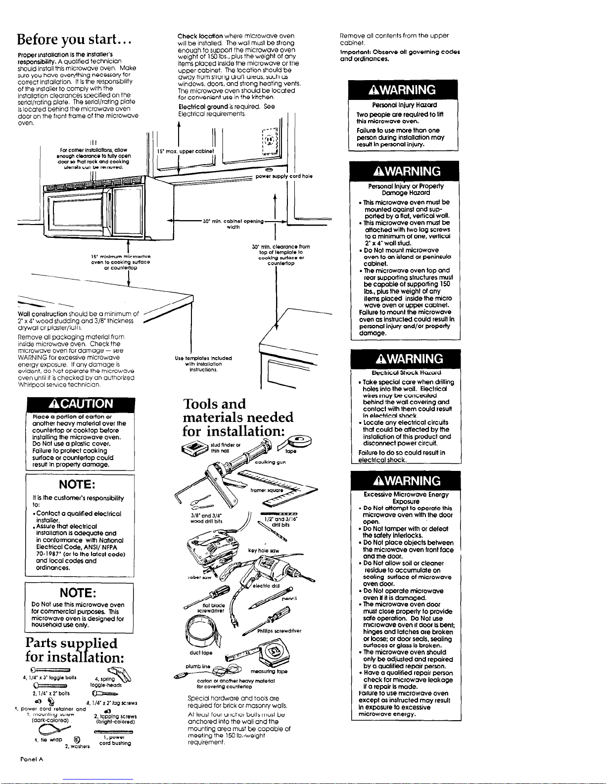
Check location where mlcrowave oven
wrll be installed. The wall must be strong
enough to support the microwave oven
weight of 1.33 Ibs.. plus the weight of any
items placed inside the microwave Or the
upper cabinet. The location should be
away from strong draft areas, such as
windows, doors, and strong heating vents.
The microwave oven should be located
for convenient use in the Kitchen.
Electrical ground is required. See
Electrical requirements.
I
Wall construction should be a minrmum of
2’ x 4’wood studding and 3/8’thickness
drywall or plaster/lath.
Remove Oil packaging material from
inside microwave oven. Check the
microwave oven for damage - see
WARNING for excessive microwave
energy exposure. If any damage is
evident, do Not operate the mrcrowave
oven until It is checked by an authorRed
Whirlpool serxe technician.
Place a porllon 01 carton or
another heavy material over the
countertop or cooktop before
installing me microwave oven.
Do Not use a plastic cover.
Failure to protect cooking
surface or counlertop could
result in property damage.
NOTE:
It is the customer’s responsibility
to:
-Contact a qualified electrical
installer.
.Assure that etectrical
installation is adequate and
in conformance Wilh National
Electrical Code. ANSI/ NFPA
70-1987’ (or to-the latest code)
and local codes and
ordinances.
I
NOTE:
I
Do Not use this microwave oven
for commercial purposes. This
microwave oven is designed lor
household use only.
Parts su
lied
for insta ation:
sp
1, Power cordretolner and
1, mounlhg Lclew
a
(dark-colored)
2. topplng screws
(bright-colored)
2. washers
cord bushing
Tools and
materials needed
Special hardware and tools are
required far brick or masonry walls.
At least four anchor baits must be
anchored into the wall and the
mounting area must be capable of
meeting the 150 lb.-weight
requirement.
Remove all contents from the upper
cabinet.
Importanl: Observe all governing codes
and ordinances.
Peryxal Injury Hazard
Two people are requlred to Ml
ihls microwave oven.
Failure to use more than one
person during installation may
resutt In personal injury.
Personal
Injury or Property
Dcnnage Hazard
. This microwave oven must be
mounted against and supported by a flat, vertical wall.
l
This microwwe oven must be
attached with two lag screws
to a minimum of one, vertical
2’ x 4’ wall stud.
. Do Not mount microwave
oven to an island or peninsula
cabinet.
l
The ticrowwe oven top and
rear supporting structures must
be capable ot supporting 150
Ibs., plus the weight of any
iterm placed inside the micro
wwe oven or upper cabinet.
Failure to mount the microwwe
oven OS instructed could result In
personal injury and/or property
damage.
l
Take special care when drilling
holes into the wall. Electrical
wires may be concealed
behind the watl covering and
contacl With them could result
in electrical shock.
l
locate any electrical circuits
that could be attested by the
installation of this product and
disconnect power circuit.
Failure to do so could result in
electrical shock.
Exposure -.
l
Do Not attempt to operate this
microwave oven wlth the door
open.
l
Do Not tamper with or defeat
the safetv Interlocks.
l
Do Not piace objects between
the microwave oven lront lace
and the door.
l
Do Not allow soil or cleaner
residue to accumulate on
sealing s&ace of microwave
oven door.
l
Do Not operate microwave
oven tt tt is damaged.
l
The microwave oven door
must close prorserlv lo provide
safe operation: Dd Noi use
microwave oven if door ls bent;
hinges and latches are broken
OT loose; or door seals, sealing
surtaces or glass is broken.
l
The microwave oven should
onlv be adiusted and rewired
by a qualiried repair pe&on.
. Hwe a qualified repair person
check for microwave leakage
it o repair is made.
Failure to use microwave oven
except as instructed may result
In exposure to excessive
microwave energy.
Panel A
Electrical
Venting
requirements
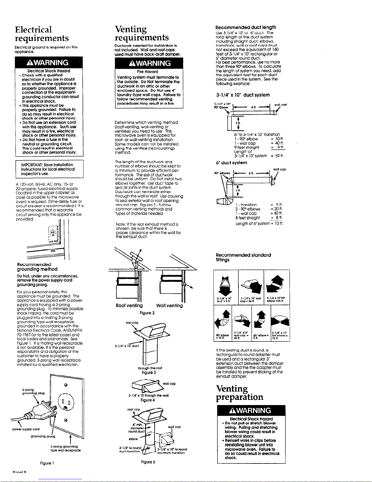
Recommended duct length
Use 3-l/4’ x lo’ or 6’ duct. The
total length of the duct system
lncludinrj straight duct. elbows.
transitions. wall or roof coos must
not exceed the equtvalerit of 140
feet of &l/4’ x lo’ rectangular or
6’ diameter round duct.
For best performance. use no more
than three 90” elbows. To calculate
the length of system you need. add
the equivalent feet for each duct
piece used In the system. See the
followlng example:
requirements
Electrical ground is required on this
appliance.
Duct&k needed for installation is
no1 included. Wall and roaf caps
used must have back-drafl damper.
Electlical Shack Hazard
. Check with a qualiried
electrician I you are In doubt
as lo whether the appliance is
properly grounded. Improper
connection d the equipmentgrounding conductor can result
in electrical shock.
l
This appliance must be
arawrlv around& Failure to
bo ia ri& resuli in electrical
shock or other personal injury.
. Da Not use an extensian cord
wiih thii appliance. Such use
may result in a fire, electrical
sh&k oi other personal injury.
. Do Not have a fuse in the
neutral or grounding circuit.
This could resutl In electrical
shock or other personal injury.
Venting system must terminate to
the outside. Do Not terminate the
ductwork in an attic or other
enclosed space. Do Not use 4
laundry-type wall caps. Failure to
follow recommended venting
procedures may result in a lire.
3-l/4’ x 10’ duct system
Determine which venting method
(roof-ventina. wall-ventina or
Gentle& yo; need to use. Tnls
microwave oven is equipped for
roof- or wall-venting instollatlon.
Some models can not be installed
using the ventless (recirculating)
method.
The length of the ductwork and
number of elbows should be kept to
o minimum to provide efficient performance. The size of ductwork
should be uniform. Do Not install two
elbows together. Use duct tape to
seal all joints in the duct system.
Ductwork can terminate either
through the wall or roof. Use caulking
to seal extetir wall or roof opening
around caa. Fiaures 2 - 5 show
common ienticg methods and
types of materials needed.
y-t&3;{gwlV transttlon
0
= ion.
1 -wall cap
= 4oft.
9 feet straight
= 9n.
Length of
31/4’xl0’system = 59n.
6’ duct system
IMFORTANI: Save Installation
r
Instructions lof local eleclrical
inspeclor’s use.
A 12Bvolt. @Hz. AC only. 15 or
Mampere. fused electncol supply
(located in the upper cabinet as
close as possible to the microwave
oven) is reauired. Ome-delav fuse or
a!$
s
in.
t
-
1 -transition
= 5n.
circuit bredker is r&ommendled.) It is
recommended that a separate
circuit serving only this appliance be
2 - 90” elbows
= mft
1 -wall cap
=4on.
8 feet straight
= an.
Length of 6’ system = 73 ft.
Note: If the rear exhaust method is
chosen, be sure that there is
proper clearance within the wall for
the exhaust duct.
Recommended standard
fittings
Recommended
grounding method
Do Not, under any circumstances,
remove the power supply cord
grounding prong.
For your personal safely. this
appliance must be grounded. This
appliance is equipped with a power
SUDDIV cord havina a 3-orona
giobnding plug. T?I minimize-pssible
shock hcaord, the cord must be
plugged into a mating Z-prong
grounding type wall receptacle,
grounded in accordance with the
National Electrical Code. ANSI/NFPA
7Ck1987 (or to the lotest code) and
loco1 codes and ordinances, See
Figure 1, If a mating wall receptacle
is not available, it is the personal
responsibility and obligation of the
customer to have a properly
grounded. 3prong wall receptacle
installed by a qualified electrician.
q
-.
Y
Wall venting
Roof venting
Figure 2
I
3.114
If the existing duct is round, a
rectangular-to-round adapter must
be used and a rectangular 3
etiensjon duct between the damaer
assembly and the the adapter m&t
be Installed to prevent sticking of the
exhaust damper.
lhrough-the-r001
Figure 3
3-l/4’ I 10 lhrough-tbwall
Figure 4
Venting
preparation
Elechtcal Shock Hazard
l
Do not pull or stretch blower
wiring. Pulling and slrelchlng
blower wiring could result in
electrical shock.
l
Reinsert wires in clips before
reinstalling blower unit Into
microwave oven. Failure lo
da so could result In electrical
Figure 5
Figure 1
 Loading...