


MH6140XKQ/B
CONSUMER SERVICES TECHNICAL
EDUCATION GROUP PRESENTS
MICROWAVE
OVEN HOOD
COMBINATION
KM-27
JOB AID
Part No. 8178053

FORWARD
This Job Aid, “Whirlpool Microwave Oven Hood Combination,” (Part No.8178053 ), provides the
technician with information on the operation and service of the Whirlpool Microwave Oven Hood
Combination. It is to be used as a training Job Aid and Service Manual. For specific information
on the model being serviced, refer to the “Use and Care Guide,” or “Tech Sheet” provided with the
microwave oven.
The Wiring Diagrams and Strip Circuits used in this Job Aid are typical and should be used for
training purposes only. Always use the Wiring Diagram supplied with the product when servicing
the unit.
GOALS AND OBJECTIVES
The goal of this Job Aid is to provide detailed information that will enable the service technician to
properly diagnose malfunctions and repair the Microwave Oven Hood Combination.
The objectives of this Job Aid are to:
• Understand and follow proper safety precautions.
• Successfully troubleshoot and diagnose malfunctions.
• Successfully perform necessary repairs.
• Successfully return the microwave oven to proper operational status.
WHIRLPOOL CORPORATION assumes no responsibility for any repairs made
on our products by anyone other than Authorized Factory Service Technicians.
Copyright © 2001, Whirlpool Corporation, Benton Harbor, MI 49022
- ii -

TABLE OF CONTENTS
Page
GENERAL............................................................................................................................... 1-1
Important Safety Information ................................................................................................ 1-1
Warning To Service Technicians ......................................................................................... 1-2
Precautions To Be Observed Before And During Servicing To Avoid
Possible Exposure To Excessive Microwave Energy ....................................................... 1-3
R.F. Leakage Test................................................................................................................ 1-4
Whirlpool Model & Serial Number Designations .................................................................. 1-5
Model & Serial Number Label And Tech Sheet Locations ................................................... 1-6
Specifications ....................................................................................................................... 1-7
Whirlpool Microwave Oven Warranty ................................................................................. 1-11
THEORY OF OPERATION ..................................................................................................... 2-1
The Vent Motor Mounting Positions ..................................................................................... 2-1
The Oven Thermostat & Vent Motor Capacitor .................................................................... 2-2
The Vent & Turntable Motors ............................................................................................... 2-3
COMPONENT ACCESS ......................................................................................................... 3-1
Component Locations .......................................................................................................... 3-1
Removing The Turntable Motor & Cooktop Lamp Assembly ............................................... 3-2
Removing The Control Panel & Control Board .................................................................... 3-4
Removing The Door Switches.............................................................................................. 3-6
Removing The Oven Lamp Assembly.................................................................................. 3-7
Removing The Oven Thermostat, Line Fuse, & Power Cord ............................................... 3-8
Removing The Vent Motor Capacitor, The High
Voltage Capacitor, & Rectifier ......................................................................................... 3-10
Removing The High Voltage Transformer.......................................................................... 3-11
Removing The Magnetron.................................................................................................. 3-12
Removing The Vent Motor ................................................................................................. 3-13
Removing The Oven Door, The Switch Actuators,
And The Outer Glass ...................................................................................................... 3-14
COMPONENT TESTING ........................................................................................................ 4-1
Touch Panel Continuity ........................................................................................................ 4-1
The Turntable & Vent Motors ............................................................................................... 4-2
The Vent Motor Capacitor, Line Fuse, Oven Thermostat,
& Door Switch ................................................................................................................... 4-3
The High Voltage Capacitor & Rectifier ............................................................................... 4-4
The High Voltage Transformer ............................................................................................. 4-5
The Magnetron ..................................................................................................................... 4-6
WIRING DIAGRAM & STRIP CIRCUITS ............................................................................... 5-1
Wiring Diagram .................................................................................................................... 5-1
Strip Circuits ......................................................................................................................... 5-2
- iii -

— NOTES —
- iv -
GENERAL
IMPORTANT SAFETY INFORMATION
Your safety and the safety of others is very important.
Important safety messages have been provided in this Job Aid. Always read and obey all
safety messages.
This is the safety alert symbol.
This symbol alerts you to hazards that can kill or hurt you
and others.
All safety messages will be preceded by the
safety alert symbol and the word “WARNING.”
All safety messages will identify the hazard, tell
you how to reduce the chance of injury, and tell
you what can happen if the instructions are not
followed.
WARNING
ELECTRICAL SHOCK HAZARD
Disconnect power before servicing.
Replace all panels before operating.
Failure to do so could result in death or
electrical shock.
IMPORTANT SAFETY
INSTRUCTIONS
Before touching any oven component or wiring, always unplug the oven from its power
source and discharge the capacitor by using a
20,000 ohm discharge resistor or use an insulated plastic handle screwdriver to short across
the capacitor terminals.
Check that the unit is grounded before troubleshooting. Be careful of the high voltage circuits.
Discharge any static charge from your body by
touching ground before handling any part of
the circuitry on the control board. Electrostatic
discharge may damage the control circuit.
Do not touch oven components or wiring during
operation. Attach meter leads with alligator
clips when making operational tests.
For continued protection against radiation
emission, replace only with these types of
switches: Primary (Interlock) Switch: SZM-V16FA-63 or VP-533A-OF; Secondary (Interlock)
Switch: SZM-V01-FA-32; Interlock (Monitor)
Switch: SZM-VI6-FA-62 or VP-532A-OF; Oven
Lamp Switch: SZM-V6-FA-31 or VP-331 AOD.
It is neither necessary nor advisable to attempt
measurement of high voltage.
Attaching the adaptor ground terminal to the
wall receptacle cover screw does not ground
the appliance unless the cover screw is metal
and not insulated and the wall receptacle is
grounded through the house wiring.
ELECTROSTATIC DISCHARGE
(ESD) SENSITIVE ELECTRONICS
ESD problems are present everywhere. ESD
may damage or weaken the electronic control assembly. The new control assembly
may appear to work well after repair is finished, but failure may occur at a later date
due to ESD stress.
• Use an antistatic wrist strap. Connect
the wrist strap to a green ground connection point or unpainted metal in the
appliance; or touch your finger repeatedly to a green ground connection point
or unpainted metal in the appliance.
• Before removing the part from its package, touch the antistatic bag to a green
ground connection point or unpainted
metal in the appliance.
• Avoid touching electronic parts or terminal contacts. Handle the electronic
control assembly by the edges only.
• When repackaging the failed electronic
control assembly in an antistatic bag,
observe the above instructions.
1-1

WARNING TO SERVICE TECHNICIANS
To avoid possible exposure to microwave radiation or energy, visually check the oven for
damage to the door and door seal before
operating any oven. Use a microwave survey
meter to check the amount of leakage before
servicing. In the event the R.F. Ieakage exceeds 4 mw/cm2 at 5 cm, appropriate repair
must be made before continuing to service the
unit. Check interlock function by operating the
door latch. The oven cook cycle should cut off
before the door can be opened.
The door and latching assembly contains the
radio frequency energy within the oven. The
door is protected by three safety interlock
switches. Do not attempt to defeat them.
Under no circumstances should you try to
operate the oven with the door open.
• Proper operation of microwave ovens requires that the magnetron be properly
assembled to the waveguide and cavity.
Never operate the magnetron unless it is
properly installed.
• Be sure the “RF” seal is not damaged and
is assembled around the magnetron dome
properly when installing the magnetron.
• Routine service safety procedures should
be exercised at all times.
• Untrained personnel should not attempt
service without a thorough review of test
procedures and safety information contained in this Job Aid.
Whirlpool microwave ovens have a monitoring
system designed to assure proper operation of
the safety interlock systems.
The interlock monitor switch will immediately
cause the oven fuse to blow if the door is
opened and the primary door interlock switch
and/or the secondary interlock switch contacts
fail in a closed position.
CAUTION: Replace a blown fuse with a 20
ampere class H fuse only.
Test the upper and lower door interlock
switches, cook relay and interlock monitor
switch (middle switch) for proper operation as
described in the component test procedures,
before replacing the blown oven fuse.
Do not attempt to repair sticking contacts
of any interlock switch, safety switch, or
Cook (Latch) relay. The components must
be replaced.
Any indication of sticking contacts during component tests requires replacement of that component to assure reliability of the safety interlock system.
If the fuse is blown, the Monitor, Primary,
and Secondary interlock switches must be
replaced. Be sure they are properly connected.
1-2

PRECAUTIONS TO BE OBSERVED BEFORE AND DURING
SERVICING TO AVOID POSSIBLE EXPOSURE
TO EXCESSIVE MICROWAVE ENERGY
A. Do not operate or allow the oven to be
operated with the door open.
B. Make the following safety checks on all
ovens to be serviced before activating the
magnetron or other microwave source,
and make repairs as necessary:
1)Interlock Operation
2)Proper Door Closing
3)Seal and Sealing Surfaces (Arcing,
Wear, and Other Damage)
4)Damage to or Loosening of Hinges and
Latches
5)Evidence of Dropping or Abuse
C. Before turning on the microwave power
for any service test or inspection within the
microwave generating components, check
the magnetron, wave guide or transmission line, and cavity for proper alignment,
integrity, and connections.
D. Any defective or misadjusted components
in the interlock, monitor, door seal, and
microwave generation and transmission
systems shall be repaired, replaced, or
adjusted, using procedures described in
this Job Aid, before the oven is released to
the owner.
E. A microwave leakage check to verify com-
pliance with Federal Performance Standard should be performed on each oven
prior to release to the owner.
F. Do not attempt to operate the oven if the
door glass is broken.
1-3

R.F. LEAKAGE TEST
EQUIPMENT
• Electromagnetic energy leakage monitor
(NARDA 81 00B, HOLADAY H 1501 ).
• 275 ±15 ML glass beaker.
TEST
On every service call, checks for microwave
energy emission must be made according to
the following manner.
1. Remove the cooking rack from the oven
cavity, if the microwave oven is so
equipped.
2. Place a 275 ±15 ML (9.3 oz.) glass of
water in the center of the oven bottom.
3. Select "HIGH" cook power, turn the micro-
wave oven on, and test for R.F. Ieakage at
the following locations:
a)Around the cabinet at the front.
b)Around the door.
c) Across the console panel.
d)Horizontally across the door.
e)Vertically across the door.
f) Diagonally across the door.
g)Across the air vents.
h)Across the rear air vent.
i) All lockseams.
j) Weld at bottom.
k) Bottom plate.
I) Oven feet.
4. The scan speed is one inch per second.
When checking for R.F. Ieakage, use an approved R.F. measuring device to assure less
than 4 mw/cm2 emission at 5 cm distance with
a maximum scan rate of 2.54 cm/second, in
compliance with U.S. Government Department
of Health, Education and Welfare 21CFR1030,
performance Standard for Microwave Ovens.
NOTE: Enter leakage readings in space BEFORE and AFTER on the service document.
All microwave ovens exceeding the emission
level of 4 mw/cm2 must be reported to Dept. of
Service for microwave ovens immediately and
the owner should be told not to use the microwave oven until it has been repaired completely.
If a microwave oven is found to operate with the
door open, report to Dept. of Service, the
manufacturer and CDRH* immediately. Also
tell the owner not to use the oven.
The interlock monitor switch acts as the final
safety switch protecting the customer from
microwave radiation. If the interlock monitor
switch operated to blow the fuse when the
interlocks failed, you must replace all interlock
switches with new ones, because the contacts
of those interlock switches may be melted and
welded together.
If safety interlock/monitor switch replacement,
or adjustment, is required, you must reconnect
the circuit, and perform a continuity check on
the monitor circuit.
All repairs must be performed in such a manner
that microwave energy emissions are minimal.
Address for CDRH is:
Office of Compliance (HFZ-342) Center for
Devices and Radiological Health
2098 Gaither Road
Rockville, MD 20850
* CDRH: Center for Devices and Radiological Health,
Food and Drug Administration.
A properly operating door and seal assembly
will normally register small emissions, but they
must be no greater than 4 mw/cm2 to allow for
measurement uncertainty.
1-4

WHIRLPOOL MODEL & SERIAL NUMBER DESIGNATIONS
MODEL NUMBER
MODEL NUMBER M H 6 14 0 X K Q 0
INTERNATIONAL SALES IND.
OR MARKETING CHANNEL
IF PRESENT
PRODUCT GROUP
G = WHIRLPOOL GOLD
M = MICROWAVE
PRODUCT IDENTIFICATION
B = BROWNER
C = CONVECTION
G = GRILL / CRISPER
H = OTR HOOD COMBO
K = KITS
M = GOLD CONVECTION
S = STIRRER FAN
T = TURNTABLE
MODEL VARIATIONS
0 - 9
CUBIC FEET
04 = .4 CU. FT. 10 = 1.0 CU. FT.
06 = .6 CU. FT. 12 = 1.2 CU. FT.
07 = .7 CU. FT. 14 = 1.4 CU. FT.
08 = .8 CU. FT. 15 = 1.5 CU. FT.
09 = .9 CU. FT. 16 = 1.6 CU. FT.
FEATURE LEVEL
0 = 30˝ KIT (IF KIT)
2 = 22˝ KIT (IF KIT)
4 = 24˝ KIT (IF KIT)
5 = SENSORED MODEL
7 = 27˝ KIT (IF KIT)
FEATURE CODE
C = CSA APPROVED
S = CARRY IN WARRANTY (EFFECTIVE 02/96)
X = IN HOME WARRANTY (EFFECTIVE O2/96)
YEAR OF INTRODUCTION
J = 2000, K = 2001, L = 2002
COLOR CODE
B = BLACK, Q = WHITE, T = BISCUIT
ENGINEERING CHANGE (0, 1, 2, ETC.)
SERIAL NUMBER
SERIAL NUMBER FG L 2 5 54321
MANUFACTURING SITE
FG = FINDLAY, OH
YEAR OF PRODUCTION
K = 2000, L = 2001
WEEK OF PRODUCTION
25TH WEEK
PRODUCT SEQUENCE NUMBER
1-5
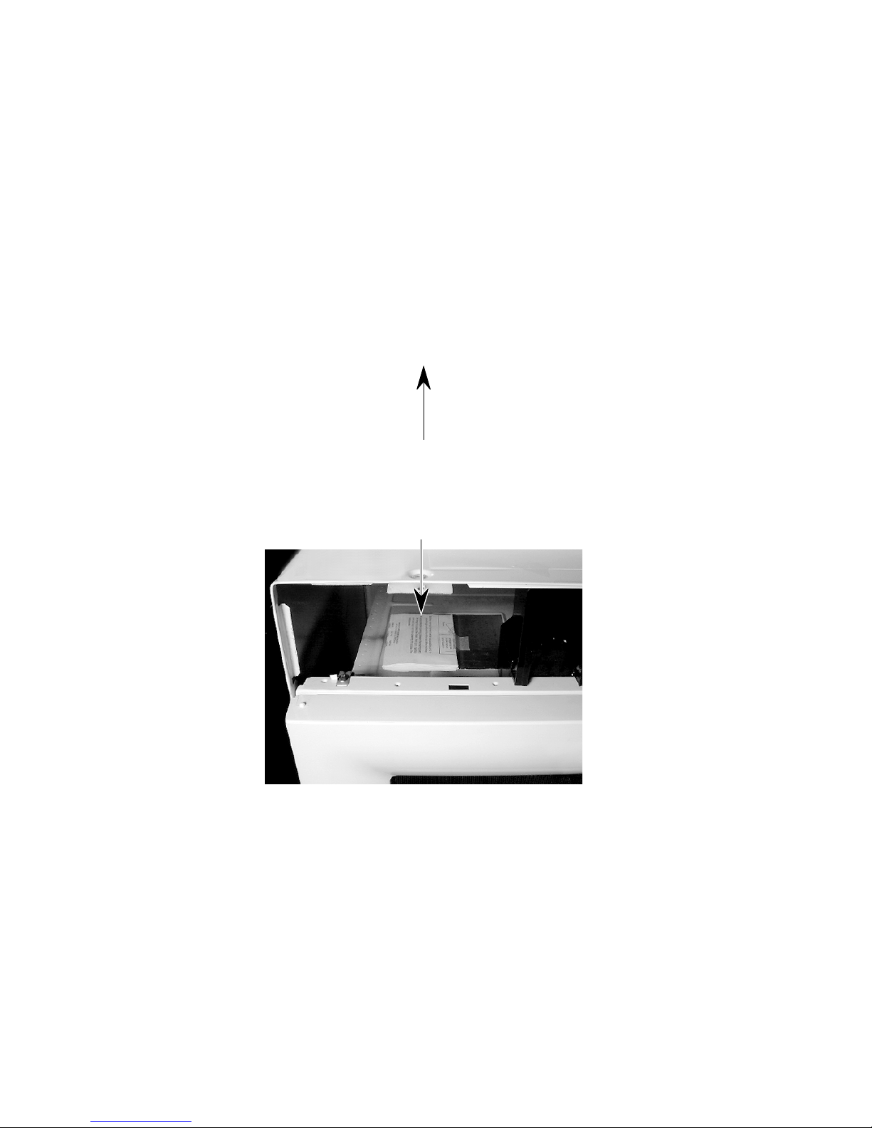
MODEL & SERIAL NUMBER LABEL
AND TECH SHEET LOCATIONS
The Model/Serial Number label and Tech Sheet locations are shown below.
Model & Serial
Number Location
Tech Sheet Location
(Behind Grille)
1-6
WHIRLPOOL
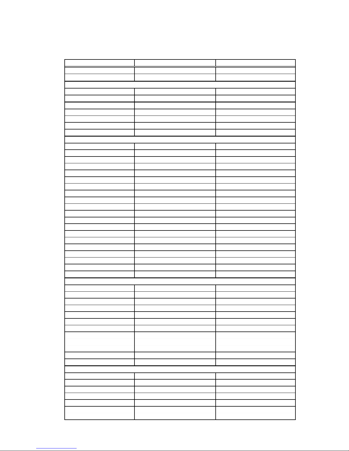
SPECIFICATIONS
MODEL
Size-Configuration
Feature Level/Series
DIMENSIONS / SPECIFICATIONS
Outside Dimensions 29-15/16" W x 16-7/16" H x 15-3/8" D 29-15/16" W x 16-7/16" H x 15-3/8" D
Interior Cavity Dimensions 19-7/8" W x 8-15/16" H x 14-3/16" D 19-7/8" W x 8-15/16" H x 14-3/16" D
CONTROL SYSTEM
Timer Electronic Electronic
Limits 99 Min. 99 Sec. 99 Min. 99 Sec.
Scale Linear (Digital) Linear (Digital)
Display 7 Digit Display Scroll VFD 7 Digit Display Scroll VFD
OTHER FEATURES
Stoppable Turntable No No
Child Lock Yes - Start / Enter Button Yes - Start / Enter Button
Variable Power (Cook Power) Yes Yes
Type Electronic Electronic
Range 10% - 100% 10% - 100%
Scale Digital Digital
Levels Ten Ten
Auto On Yes - 56 degrees C Yes - 56 degrees C
Cooktop Light Yes - One (1) Yes - One (1)
On Yes Yes
Night Yes Yes
Manual Off Yes Yes
Auto Off No No
Wattage 30 Watts 30 Watts
Light Cover Glass Glass
Start Indication "Touch Start" Scroll display "Touch Start" Scroll display
Probe Temp Indication N / A N / A
Weight Indication "Lbs" "Lbs"
Clock Set "ENTER TIME OF DAY" "ENTER TIME OF DAY"
Independent Minute Timer "ENTER TIME IN MIN AND SEC" "ENTER TIME IN MIN AND SEC"
INTERIOR
Size 19-7/8" W x 8-15/16" H x 14 -5/32" D 19-7/8" W x 8-15/16" H x 14 -5/32" D
Capacity 1.4 Cubic Feet 1.4 Cubic Feet
Finish Epoxy Powder Coat Epoxy Powder Coat
Cooking Power 950 Watts (1EC-705 Rating) 950 Watts (1EC-705 Rating)
Ventilation Forced Air Forced Air
Shelf Spillguard Sealed-In Spillguard Sealed-In
Bi-Level Rack No No
Interior Light Yes-Automatic turns on when oven Yes-Automatic turns on when oven
Turntable Diameter 12-3/4" 12-3/4"
Stoppable Turntable No No
EXTERIOR
Window Water Clear Glass Water Clear Glass
Window Size 18-1/4" W x 7-1/2" H 18-1/4" W x 7-1/2" H
Door / Window Graphics Whirlpool Logo on Door; upper left corner Whirlpool Logo on Door; upper left corner
Outer Door Stamped Steel with tempered cover Stamped Steel with tempered cover
Handle/Latch Pull to open Pull to open
Seals Three Stage Three Stage
(Capacitive, Reflective & Absorbive) (Capacitive, Reflective & Absorbive)
MH6140XKQ/B MH6141XKQ/B
1.4 cu ft 1.4 cu ft
Basic Non Sensor Basic Non Sensor
door is open or oven is operating door is open or oven is operating
30 watts (2000 hr. life) 30 watts (2000 hr. life)
1-7
MODEL
EXTERIOR FEATURES
Outside Dimensions 29-15/16" W x 16-7/16" H x 15-3/8" D 29-15/16" W x 16-7/16" H x 15-3/8" D
Control and Door Frames One Piece Molded One Piece Molded
Cooktop Light w/Touch Control One Lamp - 30 Watt Easy Access One Lamp - 30 Watt Easy Access
Power Cord Length 3.28 Ft. 3.28 Ft.
MISCELLANEOUS
MICROWAVE SYSTEM
Distribution Regular Side Feeding Regular Side Feeding
Magnetron Standard Standard
SAFETY FEATURES
Interlock Three Door/Latch Operated Three Door/Latch Operated
Thermal Protectors One (1) - Oven Cavity One (1) - Oven Cavity
VENTILATION SYSTEM
Type Convertible Convertible
Duct Outlet Size 10 " W x 3-1/4 "H 10 " W x 3-1/4 "H
Recirculation CFM 148 (Hi with Charcoal Filter) 148 (Hi with Charcoal Filter)
Horizontal CFM (Hi-Low) 223CFM / 112 CFM 223CFM / 112 CFM
Vertical CFM (Hi-Low) 220 CFM / 110 CFM 220 CFM / 110 CFM
Touch Control (2-speed) Two Speed (Hi / Low) Yes - High / Low
Auto ON - High Speed
Noise Level 43 dBA (Microwave Only) 43dBA (Microwave Only)
Damper Yes Yes
Grease Filter Yes - (2) Yes (2)
Charcoal Filter Yes - (1) Yes - (1)
Blower Type Twin Squirrel Cage Twin Squirrel Cage
Shipped Recirculating Mode Recirculating Mode
OTHER SPECIFICATIONS
Electrical 120V, Single Phase, 60 Hz, 120V, Single Phase, 60 Hz,
Domestic Use Only Yes Yes
Agency Approvals FCC, DHHS, U.L. Listed FCC, DHHS, U.L. Listed
Approx. Shipping Weight 58 lbs. 58 lbs.
Approx. Net Weight 52 lbs. 52 lbs.
Carton Dimensions 33-7/16" W x 19-5/16" H x 19-17/32" D 33-7/16" W x 19-5/16" H x 19-17/32" D
LITERATURE
Use & Care Guide 8183890 / 3828W5A1876 (English) 8183890 / 3828W5A1876 (English)
Job Aid 8178053 8178053
Cooking Guide 8183893 / 3850W3D032B (English) 8183893 / 3850W3D032B (English)
Installation Instructions 8183895 / 3828W5U0125 (English) 8183895 / 3828W5U0125 (English)
Upper Cabinet Template 8183896 / 4922W5A025A (English) 8183896 / 4922W5A025A (English)
Wall Template No No
Warranty In Use & Care Guide In Use & Care Guide
Carton Tag Std. - On Carton Corner Std. - On Carton Corner
Tech Sheet 8183894 / 3840W3T001G (English) 8183894 / 3840W3T001G (English)
ACCESSORIES
Filler Kit 4158311 4158311
Charcoal Filter 8183916 / 2B72706D 8183916 / 2B72706D
Grease Filter 4358853 / 2B72705B 4358853 / 2B72705B
Exhaust Damper Assembly Yes (1 Set) Yes (1 Set)
Trim Kit No No
Hardware for Installation Yes (1 Set) Yes (1 Set)
MH6140XKQ/B MH6141XKQ/B
Switches (1 Power Interrupt, Switches (1 Power Interrupt,
1 Monitor, 1 Low Voltage 1 Monitor, 1 Low Voltage
o
C Yes - 56oC
Yes - 56
1500 Watts, For Use With 1500 Watts, For Use With
20 Amp Circuit 20 Amp Circuit
1-8
ROPER
MODEL
Size-Configuration
Feature Level/Series Basic Non Sensor
DIMENSIONS / SPECIFICATIONS
Outside Dimensions 29-15/16" W x 16-7/16" H x 15-3/8" D
Interior Cavity Dimensions 19-7/8" W x 8-15/16" H x 14-3/16" D
CONTROL SYSTEM
Timer No
Type N / A
Limits N / A
Scale N / A
Display 7 Digit Display Scroll VFD
OTHER FEATURES
Stoppable Turntable No
Clock Yes
Child Lock Yes - Start / Enter Button
Variable Power (Cook Power) Yes
Type Electronic
Range 10% - 100% (increments of 10%)
Scale
Levels
Operation Direct Entry
Ventilation Forced Air
Exhaust Fan Yes
High Yes (220 CFM) - Vertical
Low Yes (110 CFM) - Vertical
Manual Off Yes
Auto Off No
Auto On Yes - 56 degrees C
Cooktop Light Yes - One (1)
On Yes (30 Watts)
Night Yes (17 Watts)
Manual Off Yes
INTERIOR
Size 19-7/8" W x 8-15/16" H x 14 -3/16" D
Capacity 1.4 Cubic Feet
Finish Epoxy Powder Coat
Cooking Power 950 Watts (1EC-705 Rating)
Ventilation Forced Air
Shelf No
Bi-Level Rack No
Yes-Automatic turns on when oven
Interior Light
Turntable Diameter 12-3/4"
Stoppable Turntable No
Turntable Roller Yes
EXTERIOR
Window Size 17" W x 6-7/8" H
door is open or oven is operating
MHE14XKQ/B
1.4 cu ft
Digital
Ten (10)
30 watt (2000 hr. life)
1-9
MODEL
EXTERIOR FEATURES
Outside Dimensions
Wrapper Material
Cooktop Light w/Touch Control One Lamp - 30 Watt Easy Access
Power Cord Length 3.28 Ft.
MISCELLANEOUS
MICROWAVE SYSTEM
Distribution Side Feed
Magnetron Standard
SAFETY FEATURES
Interlock
Thermal Protectors One (1) for Oven Cavity
VENTILATION SYSTEM
Type Convertible
Duct Outlet Size 10 " W x 3-1/4 "H
Recirculation CFM 148 (Hi with Charcoal Filter)
Horizontal CFM (Hi-Low) 223CFM / 112 CFM
Vertical CFM (Hi-Low) 220 CFM / 110 CFM
Touch Control (2-speed) Two Speed (Hi / Low)
Auto ON - Low Speed
Noise Level 53.5 dBA (Ventilation Mode)
Damper Yes
Grease Filter Yes - (2)
Charcoal Filter Yes - (1)
Blower Type Twin squirrel cage
Shipped Recirculating Mode
OTHER SPECIFICATIONS
Electrical
Domestic Use Only Yes
Agency Approvals FCC, DHHS, U.L. Listed
Approx. Shipping Weight 58 lbs.
Approx. Net Weight 52 lbs.
LITERATURE
Use & Care Guide Whpl # 8183914 / 3828W5A1906 (English)
Cooking Guide Whpl # 8183915 / 3850W3D032D (English)
Installation Instructions 8183895 / 3828W5U0125 (English)
Upper Cabinet Template 8183896 / 4922W5A025A (English)
Wall Template No
Warranty In Use & Care Guide
Carton Tag Std. - On Carton Corner
Model Serial Plate Location Upper Front Frame
Cooking Guide Location Upper Front Frame
Tech Sheet 8183894 / 3840W3T001G (English)
Job Aid 8178053
ACCESSORIES
Filler Kit 4158311
Charcoal Filter 8183916 / 2B72706D
Grease Filter 4358853 / 2B72705B
Exhaust Damper Assembly Yes (1 Set)
Trim Kit No
Hardware for Installation Yes (1 Set)
29-15/16" W x 16 7/16" H x 15-3/8"" D
For Black Model: Black Textured VCM
For White Model: PCM NON-Textured Steel
MHE14XKQ/B
Three Door/Latch Operated
Switches (1 Power Interrupt,
1 Monitor, 1 Low Voltage)
o
Yes - 56
C
120V, Single Phase, 60 Hz,
1500 Watts, For Use With
20 Amp Circuit
1-10

WHIRLPOOL MICROWAVE OVEN WARRANTY
LENGTH OF
WARRANTY:
ONE-YEAR FULL
WARRANTY
From Date of
Purchase.
LIMITED FOURYEAR WARRANTY Second
through fifth year
from Date of
Purchase.
WHIRLPOOL
WILL PAY FOR:
FSP ® Replacement parts and
repair labor costs
to correct defects
in materials or
workmanship.
Service must be
provided by a
Whirlpool-designated servicing
company.
FSP ® Replacement magnetron
tube on microwave
ovens if defective
in materials or
workmanship.
WHIRLPOOL
WILL NOT PAY FOR:
A. Service calls to:
1. Correct the installation of the microwave
oven.
2. Instruct you how to use the microwave
oven.
3. Replace house fuses or correct house
wiring.
4. Replace owner-accessible light bulbs.
B. Repairs when microwave oven is used in
other than normal single-family household
use.
C. In-home service. Your microwave oven must
be taken to a Whirlpool-designated service
company, except when your microwave oven
is installed over an approved oven using an
approved built-in kit.
D. Damage to the microwave oven resulting
from accident, alteration, misuse, abuse, fire,
flood, acts of God, or use of products not
approved by Whirlpool Corporation.
E. Any labor costs during the limited warranty.
F. Repairs to parts or systems resulting from
unauthorized modifications made to the
appliance.
G. Replacement parts or repair labor costs for
units operated outside the United States.
WHIRLPOOL CORPORATION SHALL NOT BE LIABLE FOR INCIDENTAL OR CONSEQUENTIAL DAMAGES. Some states do not allow the exclusion or limitation of incidental or
consequential damages, so this exclusion or limitation may not apply to you. This warranty
gives you specific legal rights, and you may also have other rights which vary from state to
state.
Outside the United States, this warranty does not apply. Contact your authorized Whirlpool dealer to determine if another warranty applies.
If you need service, see the “Requesting Assistance or Service” in the Use & Care Guide, or by
calling our Customer Interaction Center telephone number, 1-800-253-1301, from anywhere in
the U.S.A.
1-11
 Loading...