

Whirlpool MH3184XPB, GH4184XSB, GH4814XSS Service Manual
CONSUMER SERVICES TECHNICAL
EDUCATION GROUP PRESENTS
MICROWAVE
OVEN/HOOD COMBINATION
JOB AID
Part No. 8178707
KM-31
Models MH3184XPB, GH4184XSB & GH4814XSS

Appli anc eA ss istant. co m
For More Appliance Troubleshooting, Repair Help, & DIY Videos
Visit
A
Note: This Page was not included by Whirlpool Corporation
ApplianceAssistant.com is not affiliated Whirlpool Corporation
Whirlpool Corporation in no way endorses ApplianceAssistant.com

FORWARD
This Whirlpool Job Aid, “Microwave Oven / Hood Combination” (Part No. 8178707) provides the
In-Home Service Professional with information on the installation, operation, and service of the
Microwave Oven / Hood Combination. For specific information on the model being serviced,
refer to the Use and Care Guide or Tech Sheet provided with the Microwave Oven / Hood Combination.
The Wiring Diagram and Strip Circuits used in this Job Aid are typical and should be used for
training purposes only. Always use the Wiring Diagram supplied with the product when servicing
the unit.
GOALS AND OBJECTIVES
The goal of this Job Aid is to provide information that will enable the In-Home Service Professional to properly diagnose malfunctions and repair the KitchenAid Microwave Oven / Hood
Combination.
The objectives of this Job Aid are to:
Understand and follow proper safety precautions.•
Successfully troubleshoot and diagnose malfunctions.•
Successfully perform necessary repairs.•
Successfully return the microwave oven to its proper operational status.•
WHIRLPOOL CORPORATION assumes no responsibility for any repairs made on
our products by anyone other than authorized In-Home Service Professionals.
Copyright © 2007, Whirlpool Corporation, Benton Harbor, MI 49022
- ii -

TABLE OF CONTENTS
Page
GENERAL . . . . . . . . . . . . . . . . . . . . . . . . . . . . . . . . . . . . . . . . . . . . . . . . . . . . . . . . . . . . . . 1-1
Microwave Oven Safety. . . . . . . . . . . . . . . . . . . . . . . . . . . . . . . . . . . . . . . . . . . . . . . . . . . 1-1
Precautions to Be Observed Before and During Servicing to Avoid
Possible Exposure to Excessive Microwave Energy ........................... 1-2
Model and Serial Number Designations . . . . . . . . . . . . . . . . . . . . . . . . . . . . . . . . . . . . . . 1-3
Model and Serial Number Label and Tech Sheet Locations . . . . . . . . . . . . . . . . . . . . . . . 1-4
Specifications . . . . . . . . . . . . . . . . . . . . . . . . . . . . . . . . . . . . . . . . . . . . . . . . . . . . . . . . . . 1-5
INSTALLATION INFORMATION ............................................. 2-1
Installation Requirements . . . . . . . . . . . . . . . . . . . . . . . . . . . . . . . . . . . . . . . . . . . . . . . . . 2-1
Installation Instructions . . . . . . . . . . . . . . . . . . . . . . . . . . . . . . . . . . . . . . . . . . . . . . . . . . . 2-3
PRODUCT OPERATION .................................................... 3-1
Parts and Features . . . . . . . . . . . . . . . . . . . . . . . . . . . . . . . . . . . . . . . . . . . . . . . . . . . . . . 3-1
Microwave Oven Control .................................................. 3-2
COMPONENT ACCESS .................................................. 4-1
Component Locations . . . . . . . . . . . . . . . . . . . . . . . . . . . . . . . . . . . . . . . . . . . . . . . . . . . . 4-1
Removing a Hood Lamp Socket and Bottom Cover . . . . . . . . . . . . . . . . . . . . . . . . . . . . . 4-2
Removing the Cabinet .................................................... 4-4
Removing Cavity Thermostat #3 and the Humidity Sensor ........................ 4-5
Removing the Hood Exhaust Fan Motor ...................................... 4-8
Removing the Cavity Lamp Holder, the Stirrer Motor
and Cavity Thermostat #2 ............................................... 4-9
Removing Cavity Thermostat #1, the Motor Capacitor,
the AC Line Filter and the Power Supply Cord . . . . . . . . . . . . . . . . . . . . . . . . . . . . . . 4-12
Removing the Electronic Control Board and the Touch Control Assembly . . . . . . . . . . . 4-14
Removing the Primary, Secondary and Monitor Interlock Switches ................ 4-16
Removing the Line Fuse Holder and the Magnetron Thermostat . . . . . . . . . . . . . . . . . . 4-18
Removing the Cooling Fan Motor and the Exhaust Fan Thermostat . . . . . . . . . . . . . . . 4-19
Removing High-Voltage Diode and the Power Resistor . . . . . . . . . . . . . . . . . . . . . . . . . 4-20
Removing the High-Voltage Capacitor and the Magnetron ....................... 4-21
Removing the High-Voltage Transformer . . . . . . . . . . . . . . . . . . . . . . . . . . . . . . . . . . . . 4-24
Removing the Turntable Motor . . . . . . . . . . . . . . . . . . . . . . . . . . . . . . . . . . . . . . . . . . . . 4-25
Removing the Oven Door and Components . . . . . . . . . . . . . . . . . . . . . . . . . . . . . . . . . . 4-26
- iii -

Page
COMPONENT TESTING . . . . . . . . . . . . . . . . . . . . . . . . . . . . . . . . . . . . . . . . . . . . . . . . . . . 5-1
Thermostats ............................................................ 5-1
Humidity Sensor . . . . . . . . . . . . . . . . . . . . . . . . . . . . . . . . . . . . . . . . . . . . . . . . . . . . . . . . 5-2
Hood Exhaust Fan Motor. . . . . . . . . . . . . . . . . . . . . . . . . . . . . . . . . . . . . . . . . . . . . . . . . . 5-2
Stirrer Motor ............................................................ 5-3
Motor Capacitor ......................................................... 5-3
AC Line Filter ........................................................... 5-4
Door Interlock Switches ................................................... 5-4
Line Fuse .............................................................. 5-5
Cooling Fan Motor ....................................................... 5-5
High-Voltage Diode . . . . . . . . . . . . . . . . . . . . . . . . . . . . . . . . . . . . . . . . . . . . . . . . . . . . . . 5-6
Power Resistor . . . . . . . . . . . . . . . . . . . . . . . . . . . . . . . . . . . . . . . . . . . . . . . . . . . . . . . . . 5-6
High-Voltage Capacitor . . . . . . . . . . . . . . . . . . . . . . . . . . . . . . . . . . . . . . . . . . . . . . . . . . . 5-7
Magnetron ............................................................. 5-7
High-Voltage Transformer . . . . . . . . . . . . . . . . . . . . . . . . . . . . . . . . . . . . . . . . . . . . . . . . . 5-8
Turntable Motor ......................................................... 5-8
DIAGNOSTICS AND TROUBLESHOOTING . . . . . . . . . . . . . . . . . . . . . . . . . . . . . . . . . . . 6-1
Primary, Secondary and Monitor Interlock Switch Checkout Procedure .............. 6-1
Failure Code Indications . . . . . . . . . . . . . . . . . . . . . . . . . . . . . . . . . . . . . . . . . . . . . . . . . . 6-2
Touch Panel and Electronic Control Test ...................................... 6-3
Microwave Oven Power Output Test ......................................... 6-4
WIRING DIAGRAM AND STRIP CIRCUITS . . . . . . . . . . . . . . . . . . . . . . . . . . . . . . . . . . . . 7-1
Wiring Diagram . . . . . . . . . . . . . . . . . . . . . . . . . . . . . . . . . . . . . . . . . . . . . . . . . . . . . . . . . 7-1
Strip Circuits . . . . . . . . . . . . . . . . . . . . . . . . . . . . . . . . . . . . . . . . . . . . . . . . . . . . . . . . . . . 7-2
- iv -
GENERAL
DANGER
WARNING
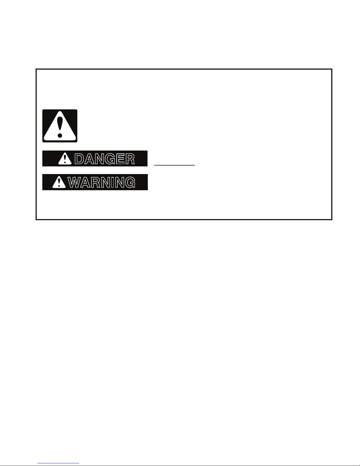
MICROWAVE OVEN SAFETY
Your safety and the safety of others are very important.
We have provided many important safety messages in this manual and on your appliance.
Always read and obey all safety messages.
This is the safety alert symbol.
This symbol alerts you to potential hazards that can kill or hurt you and others.
All safety messages will follow the safety alert symbol and either the word
“DANGER” or “WARNING.” These words mean:
You can be killed or seriously injured if you don’t
immediately follow instructions.
You can be killed or seriously injured if you don’t
follow instructions.
All safety messages will tell you what the potential hazard is, tell you how to reduce the chance
of injury, and tell you what can happen if the instructions are not followed.
1-1

PRECAUTIONS TO BE OBSERVED BEFORE AND
DURING SERVICING TO AVOID POSSIBLE EXPOSURE
TO EXCESSIVE MICROWAVE ENERGY
a) Do not operate or allow the oven to be operated with the door open.
b) Make the following safety checks on all ovens to be serviced before activating the
magnetron or other microwave source, and make repairs as necessary:
1. Interlock Operation
2. Proper Door Closing
3. Seal and Sealing Surfaces (Arcing, Wear and Other Damage)
4. Damage to or Loosening of Hinges and Latches
5. Evidence of Dropping or Abuse
c) Before turning on microwave power for any service test or inspection within the microwave
generating compartments, check the magnetron, waveguide or transmission line, and
cavity for proper alignment, integrity and connections.
d) Any defective or misadjusted components in the interlock, monitor, door seal, and micro-
wave generation and transmission systems shall be repaired, replaced, or adjusted by
procedures described in service manual before the oven is released to the owner.
e) A microwave leakage check to verify compliance with the Federal Performance Standard
should be performed on each oven prior to release to the owner.
f) Do not attempt to operate the oven if the door glass is broken.
1-2

MODEL AND SERIAL NUMBER DESIGNATIONS
MODEL NUMBER
INTERNATIONAL SALES IND.
OR MARKETING CHANNEL
IF PRESENT
PRODUCT GROUP
G = WHIRLPOOL GOLD
M = MICROWAVE
PRODUCT IDENTIFICATION
B = BROWNER
C = CONVECTION
G = GRILL / CRISPER
H = O-T-R HOOD COMBO
K = KITS
M = CONVECTION (GOLD)
S = STIRRER FAN
T = TURNTABLE
MODEL VARIATIONS
0 - 9
CUBIC FEET
04 = 0.4 CU FT 13 = 1.3 CU FT
06 = 0.6 CU FT 14 = 1.4 CU FT
07 = 0.7 CU FT 15 = 1.5 CU FT
08 = 0.8 CU FT 16 = 1.6 CU FT
09 = 0.9 CU FT 17 = 1.7 CU FT
10 = 1.0 CU FT 18 = 1.8 CU FT
11 = 1.1 CU FT 19 = 1.9 CU FT
12 = 1.2 CU FT
FEATURE LEVEL
0 = 30" KIT (IF KIT)
2 = 22" KIT (IF KIT)
4 = 24" KIT (IF KIT)
5 = SENSORED MODEL
7 = 27" KIT (IF KIT)
FEATURE CODE
C = CSA APPROVED
N = I-enabled with In-Home Warranty
S = CARRY IN WARRANTY (effective 02/96)
X = IN HOME WARRANTY (effective 02/96)
YEAR OF INTRODUCTION
S = 2006 T = 2007
COLOR CODE Q = WHITE B = BLACK S = STAINLESS T = BISCUIT
ENGINEERING CHANGE (NUMERIC)
M H 3 18 4 X S B 0
SERIAL NUMBER
TR T 44 10023
MANUFACTURING SITE
TR = SHUNDE, CHINA
YEAR OF PRODUCTION
T = 2006 U = 2007
WEEK OF PRODUCTION
44TH WEEK
PRODUCT SEQUENCE NUMBER
1-3
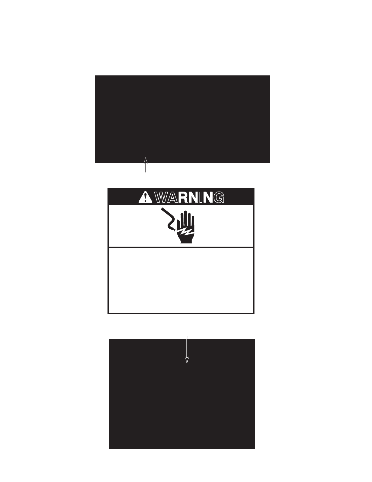
MODEL AND SERIAL NUMBER LABEL AND
WARNING
TECH SHEET LOCATIONS
The Model/Serial Number label and Tech Sheet locations are shown below.
Model/Serial Number Label
Disconnect power before servicing.
Replace all parts and panels before
operating.
Failure to do so can result in death or
electrical shock.
Electrical Shock Hazard
Tech Sheet Location
1-4

SPECIFICATIONS
Model MH3184XPQ/B/T/S
Control System Sensor
Timer Electronic
Limits 99 min. 99 sec.
Operation Touch Control
Display 5 + 2 Digit - Blue-Green
Fluorescent - Callouts In Display
Type Electronic
Range 0% - 100%
Scale Digital
Levels Ten
Operation Direct Entry
Exhaust Fan Yes - One Key Operation
Number of Speeds 4
Manual Off Yes
Automatic Turn On @ 60° C, 140°F
Manual Off Yes
Cooktop Light Incadescent
Settings High, Night, Off
Wattage (2) 30 Watt
Light Cover Glass
Size (in) (2) 2 1/2" X 4 3/4"
Technical Error Indication "F-" With Error Number
Diagnostic System Yes
Oven Interior Features
Size (Inches) 22 7/8" w x 9 1/2" h x 14 1/2" d
Size (Metric) 580 mm W x 236 mm H x 370 mm D
Capacity 1.8 Cu. Ft.
Finish Powder Coating
Cooking Power 1000 Watts
Glass Turntable Diameter
Ventilation Standard Air Flow System
Cooling Fan Automatic: On if Oven Is Operating; Off If Door Is Open
Door Features
Side Swing Left-Hand (Hinge Side)
Seals Two-Stage
Microwave System
Distribution Top Feed w/ Stirrer
Magnetron Standard Transformer
Safety Features
Interlock 3 Door/Latch Operated Primary, Secondary and Monitor
Thermal Protectors 5 - 1 Magnetron, 1 Oven Cavity, 1 Hood, 2 Wave Guide
12˝
1-5
Ventilation System
Type Convertible Recirculation or Exhaust Vertical/Horizontal
Duct Outlet Size 3 1/4"H x 10"W
Recirculation CFM Out 260
Exhaust CFM Out 200
Touch Control 4-Speed
Auto On/High Speed
Blower Type Twin Squirrel Cage
Shipped Recirculation Mode
Exterior Features
Cabinet Finish White, Black, Biscuit, Black for Stainless
Cooktop Light w/Touch Control
Power Cord Length 3 Feet
Other Specications
Electrical
Domestic Use Only Yes
Agency Approvals FCC, DHHS, CDRH, UL
Approx. Net Weight - Lb 62 Lbs.
APPROVED ACCESSORIES
Hardware for Installation Yes (1 Set)
Literature
Use & Care Guide 8205959
Warranty In Use & Care Guide-1 Yr. Full, 2-5 Yr. Ltd. Mag. Tube
Tech Sheet 8205606
Yes: 140°F / 60°C
2 Lamps - 30 Watt Easy Access
120 VAC, Single Phase, 60 Hz
1500 Watts, For Use With 15-20 Amp Circuit
1-6

SPECIFICATIONS
Model GH4184XSB and GH4184XSS
Control System Sensor
Timer Electronic
Limits 99 min. 99 sec.
Operation Touch Control
Display 5 + 2 Digit - Blue-Green with lter
Fluorescent - Callouts In Display
Type Electronic
Range 0% - 100%
Scale Linear (Digital)
Levels Ten
Operation Direct Entry
Exhaust Fan Yes - One Key Operation
Number of Speeds 4
Manual Off Yes
Automatic Turn On @ 60° C, 140°F
Manual Off Yes
Cooktop Light Incadescent
Settings 3 levels (High, Night, Off)
Wattage (2) 30 Watt
Light Cover Glass
Size (in) (2) 2 1/2" X 4 3/4"
Technical Error Indication "F-" With Error Number
Diagnostic System Yes
Oven Interior Features
Size (Inches) 22 7/8" w x 9 1/2" h x 14 1/2" d
Size (Metric) 580 mm W x 236 mm H x 370 mm D
Capacity 1.8 Cu. Ft.
Turn Table Yes, Sunken Flush (12" dia)
Ventilation Standard Air Flow System
Cooling Fan Automatic: On if Oven Is Operating; Off If Door Is Open
Light Automatic - Turns on when oven door is open or oven is oper-
ating. 30 Watt
Door Features
Seals Two-Stage (Capacitive and Reective)
Microwave System
Distribution Top Feed w/ Stirrer
Magnetron Standard Transformer
Safety Features
Interlock 3 Door/Latch Operated Primary, Secondary and Monitor
Thermal Protectors 5 - 1 Magnetron, 1 Oven Cavity, 1 Hood, 2 Wave Guide
1-7

Ventilation System
Type Convertible Recirculation or Exhaust Vertical/Horizontal
Duct Outlet Size 3 1/4"H x 10"W
Recirculation CFM Out 260
Exhaust CFM Out 200
Touch Control 4-Speed
Auto On/High Speed
Blower Type Twin Squirrel Cage
Shipped Recirculation Mode
Exterior Features
Outside Dimensions (in)
Power Cord Length 3 Feet
Other Specications
Electrical
Domestic Use Only Yes
Agency Approvals FCC, DHHS, CDRH, UL
Approx. Net Weight - Lb 55 Lbs.
APPROVED ACCESSORIES
Tupperware Steam Cook
Vessel
Exhaust Damper Assembly Yes (1 Set)
Hardware for Installation Yes (1 Set)
Literature
Use & Care Guide 8206416
Installation Instructions Yes
Warranty In Use & Care Guide-1 Yr. Limited
Tech Sheet 8205607
Yes: 140°F / 60°C
29 7/8" W x 17 1/4" H x 15 7/16" D
120 VAC, Single Phase, 60 Hz
1500 Watts, For Use With 15-20 Amp Circuit
No -optional
1-8
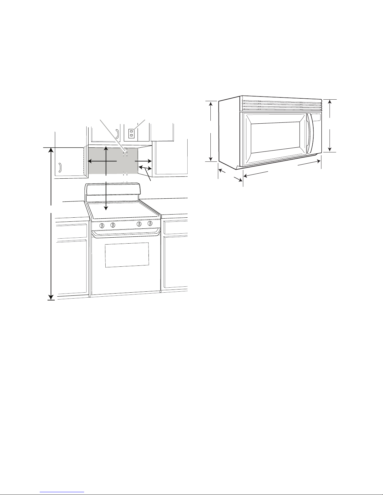
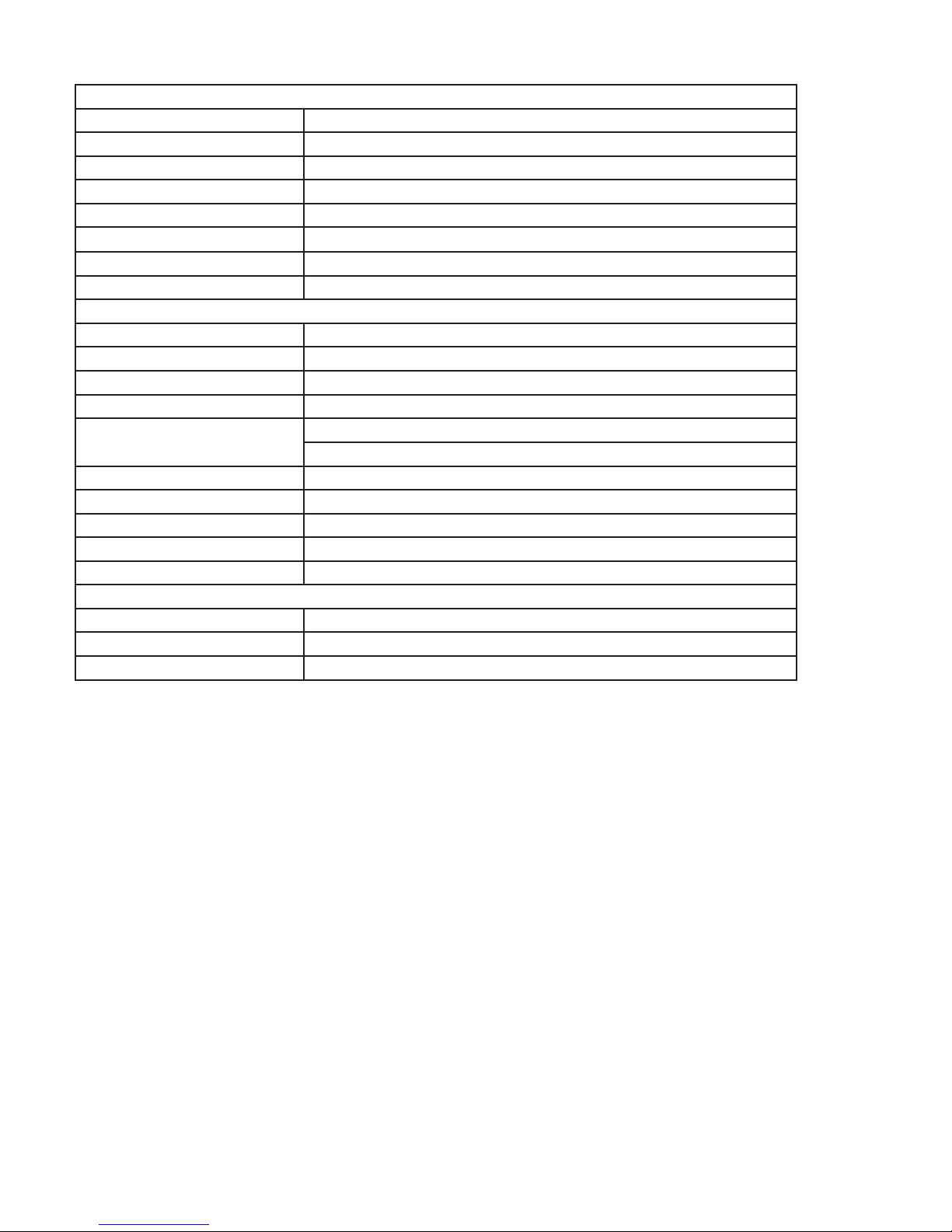
INSTALLATION INFORMATION
*30" (76.2 cm) is typical for 66" (167.6 cm) installation height.
Exact dimensions may vary depending on type of range/
cooktop below.
A. 2" x 4" wall stud
B. Grounded 3 prong outlet
66" (167.6 cm) min.
12" (30.5 cm) min.
14" (35.6 cm) max.
A B
30" (76.2 cm) typical*
30"
(76.2 cm)
min.
29
7⁄8
" (75.9 cm)
15
3⁄8
"
(39.1 cm)
17
1⁄8
"
(
43.5 cm)
15
7⁄8
"
(40.3 cm)
INSTALLATION REQUIREMENTS
INSTALLATION DIMENSIONS
NOTE: The grounded 3 prong outlet must be
inside the upper cabinet. See “Electrical Requirements,” page 2-2.
PRODUCT DIMENSIONS
2-1
WARNING
ELECTRICAL REQUIREMENTS
Electrical Shock Hazard
Plug into a grounded 3 prong outlet.
Do not remove ground prong.
Do not use an adapter.
Do not use an extension cord.
Failure to follow these instructions can
result in death, fire, or electrical shock.
Observe all governing codes and ordinances.
Required:
A 120 Volt, 60 Hz, AC only, 15- or 20-amp •
fused electrical supply (or circuit breaker).
Recommended:
GROUNDING INSTRUCTIONS
For all cord connected appliances:•
The microwave oven must be grounded.
In the event of an electrical short circuit,
grounding reduces the risk of electric
shock by providing an escape wire for
the electric current. The microwave oven
is equipped with a cord having a grounding wire with a grounding plug. The plug
must be plugged into an outlet that is
properly installed and grounded.
WARNING: Improper use of the ground-
ing plug can result in a risk of electric
shock. Consult a qualified electrician
or serviceman if the grounding instructions are not completely understood, or
if doubt exists as to whether the microwave oven is properly grounded.
Do not use an extension cord. If the
power supply cord is too short, have a
qualified electrician or serviceman install
an outlet near the microwave oven.
A time-delay fuse or circuit breaker is •
recommended.
A separate circuit serving only this micro-•
wave oven.
2-2
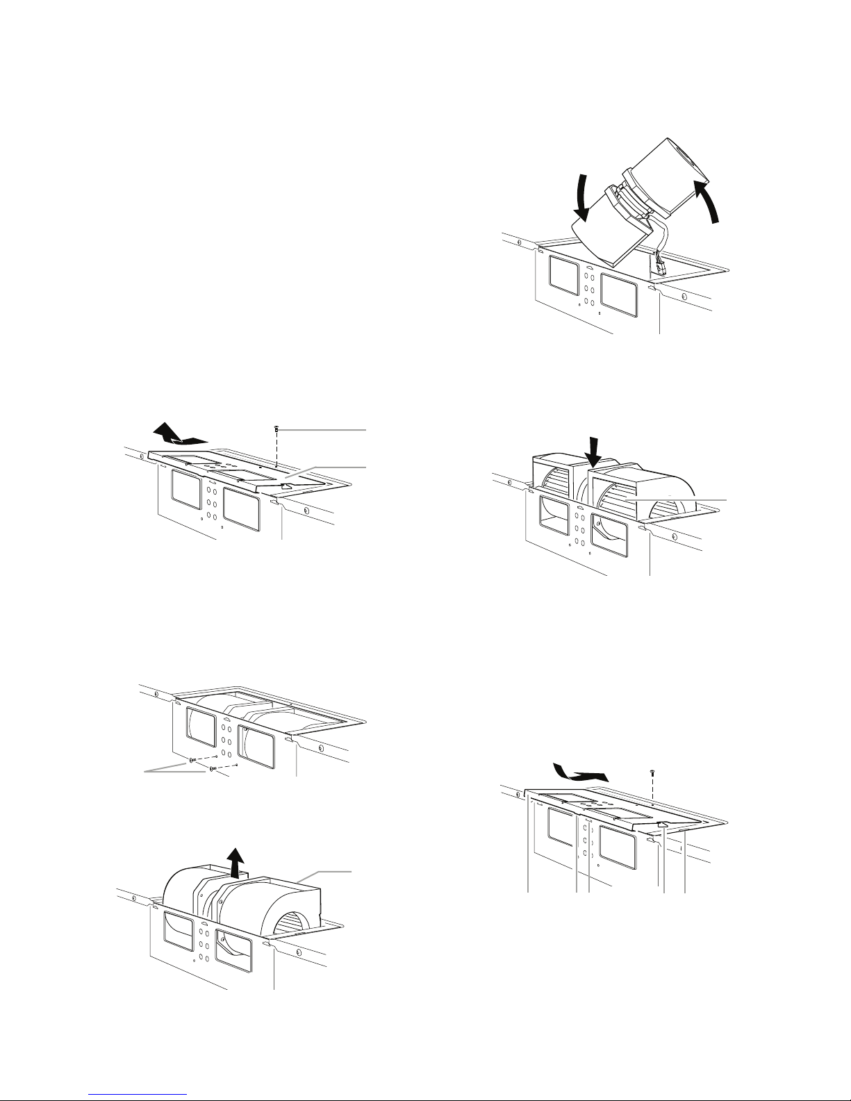
INSTALLATION INSTRUCTIONS
AScrew
B. Damper plate
A
B
A. Screws
A
A. Blower motor
A
A
A. Exhaust port
A. Damper plate
B. Tabs at back of damper plate
C. Slots in back of microwave oven exterio
r
D. Damper plate tabs
E. Slots in top of microwave oven exterior
A B C D E
ROTATE BLOWER MOTOR
The microwave oven is set for recirculation
installation. For wall or roof venting, changes
must be made to the venting system.
NOTE: Skip this section if you are using recirculation installation. Keep the damper assembly in case the venting method is changed, or
the microwave oven is reinstalled in another
location where wall or roof venting may be
used.
Wall Venting Installation Only
1. Remove screw attaching damper plate
to top of microwave oven exterior. Slide
damper plate back and lift up.
5. Rotate blower motor end over end.
6. Rotate blower motor so that exhaust
ports face the back of microwave oven,
and lower blower motor back into the
microwave oven.
2. Keep damper plate and screw together
and set aside.
3. Remove two screws attaching blower
motor to back of microwave oven.
4. Lift blower motor out of microwave oven.
7. Reattach blower motor to back of
microwave oven with 2 screws removed
in Step 3.
8. Reattach damper plate. Make sure tabs
at top and back of damper plate are inserted fully into their respective slots in
the microwave oven.
9. Secure damper plate with screw.
2-3
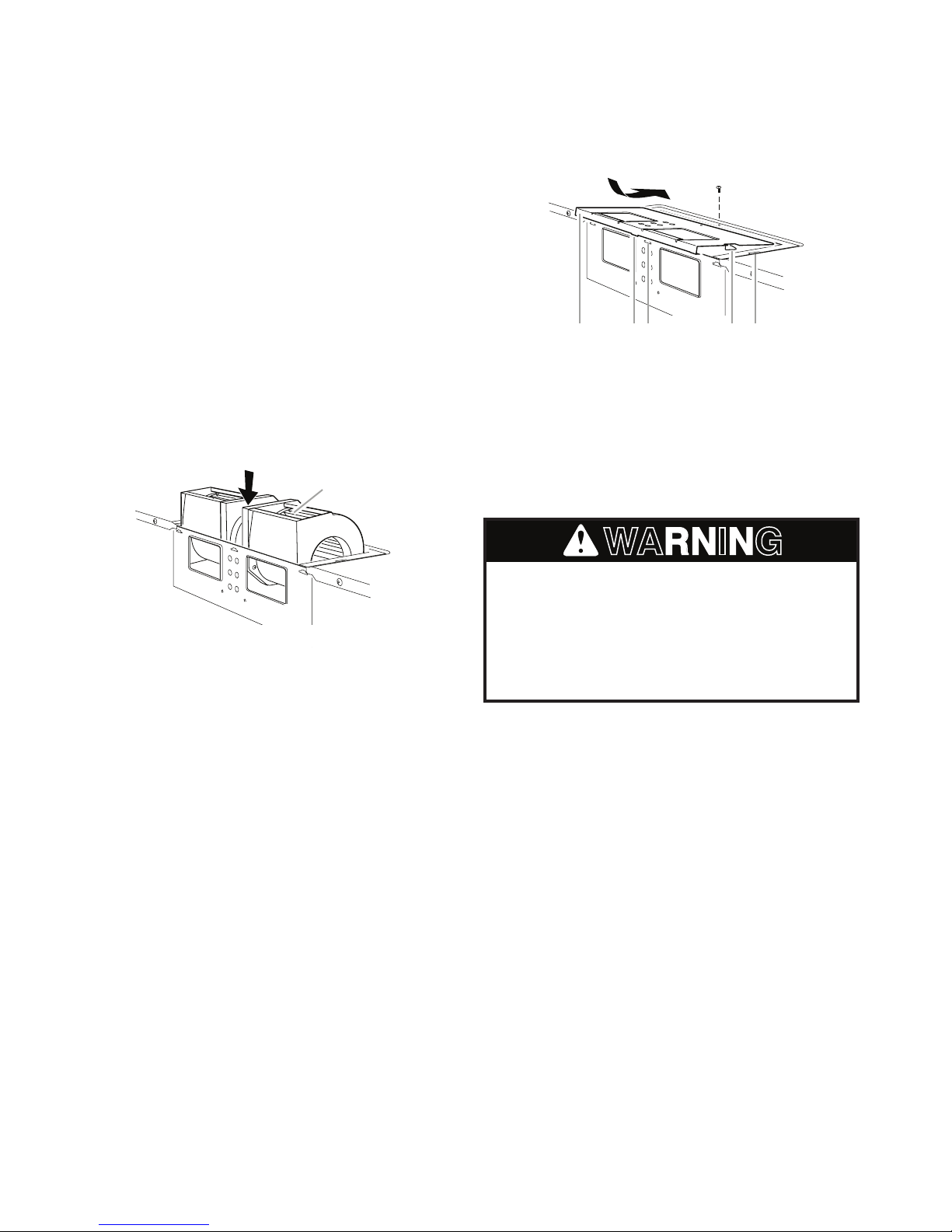
A. Exhaust port
A
Roof Venting Installation Only
A. Damper plate
B. Tabs at back of damper plate
C. Slots in back of microwave oven exterio
r
D. Damper plate tabs
E. Slots in top of microwave oven exterior
A B C D E
WARNING
1. Repeat Step 1 from “Wall Venting Installation Only.”
2. Repeat Step 2 from “Wall Venting Installation Only.”
3. Repeat Step 3 from “Wall Venting Installation Only.”
4. Repeat Step 4 from “Wall Venting Installation Only.”
5. Rotate the blower motor so the exhaust
ports face the top of the microwave oven
and the flat sides of the blower motor
face the back of the microwave oven.
Lower the blower motor back into the
microwave oven.
7. Reattach damper plate. Make sure tabs
at top and back of damper plate are inserted fully into their respective slots in
the microwave oven.
8. Secure damper plate with screw.
INSTALL THE MICROWAVE OVEN
IMPORTANT: If blower motor is not posi-
tioned with flat sides facing the back of the
microwave oven (as shown), performance will
be poor.
6. Reattach blower motor to back of microwave oven with 2 screws removed in
Step 3 of “Wall Venting Installation Only.”
Securely tighten screws.
NOTE: If blower motor is not correctly oriented, the 2 screws removed in Step 3 cannot be
reattached to the microwave oven.
Excessive Weight Hazard
Use two or more people to move and
install microwave oven.
Failure to do so can result in back or
other injury.
IMPORTANT: The control side of the
microwave oven is the heavy side. Handle the
microwave oven gently.
1. Place a washer on each 1/4-20 x 3˝ bolt
and place inside upper cabinet near the
3/8˝ (10 mm) holes.
2. Make sure the microwave oven door is
closed and taped shut.
2-4
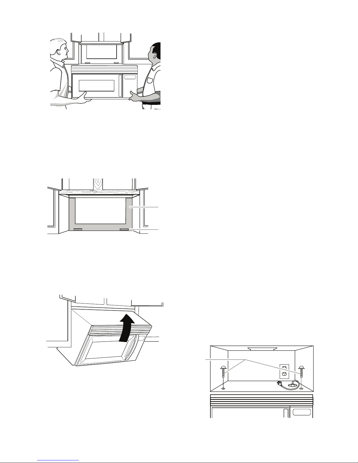
A. Mounting plate
B. Support tabs
A
B
5. Rotate the microwave oven up toward
A. Bolts
A
upper cabinet.
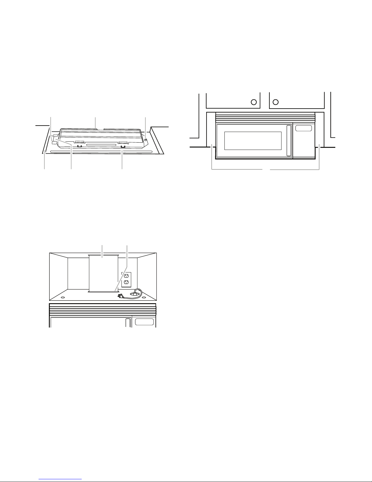
NOTE: If venting through the wall, make sure
the damper assembly fits easily into the vent
in the wall cutout.
6. Push the microwave oven against mounting plate and hold in place.
NOTE: If microwave oven does not need to
be adjusted, skip steps 7-9.
3. Using 2 or more people, lift microwave
oven and hang it on support tabs at the
bottom of mounting plate.
NOTE: To avoid damage to the microwave
oven, do not grip or use the door or door
handle while the microwave oven is being
handled.
4. With front of microwave oven still tilted,
thread power supply cord through the
power supply cord hole in the bottom of
the upper cabinet.
7. If adjustment is required, rotate the
microwave oven downward. Using 2 or
more people, lift microwave oven off of
mounting plate, and set aside on a protected surface.
8. Loosen mounting plate screws. Adjust
mounting plate and retighten screws.
9. Repeat steps 3-6.
10. With the microwave oven centered, and
with at least one person holding it in
place, insert bolts through upper cabinet
into microwave oven. Tighten bolts until
there is no gap between upper cabinet
and microwave oven.
NOTES:
Some upper cabinets may require bolts •
longer or shorter than 3˝ (7.6 cm). Longer
or shorter bolts are available at most hardware stores.
Overtightening bolts may warp the top •
of the microwave oven. To avoid warping, wood filler blocks may be added. The
blocks must be the same thickness as the
space between the upper cabinet bottom
and the microwave oven.
2-5
For Roof Venting Installation Only
A. Raised tabs
B. Damper assembly
C. Sheet metal screw
D. Upper cabinet cutout
E. Long tab
F. Damper plate
A B C
D E F
A. Vent
B. Damper assembly (under vent)
A B
A. Filler panels
A
1. Insert damper assembly through the
cabinet cutout so that the long tab of the
damper assembly slides under the raised
tabs of the damper plate. Then secure
with sheet metal screw.
NOTE: The screw cannot be installed if the
damper assembly is not positioned as shown.
2. Connect vent to damper assembly.
ACCESSORIES
Filler Panel Kits are available from your
dealer to use when installing this microwave
oven in a 36˝ (91.4 cm) or 42˝ (106.7 cm) wide
opening. The filler panels come in pairs. Each
panel is 3˝ (7.6 cm) wide.
Filler Panel Kit Number 8171336 White
8171337 Black
8171338 Biscuit
8171339 Stainless Steel
99403 Almond
See your authorized dealer or service center
for details.
2-6
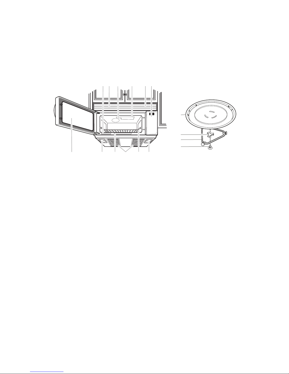
PRODUCT OPERATION
A. Model and Serial Number Plate
B. Charcoal Filter
(behind Vent Grille)
C. Microwave Inlet Cover
D. Microwave Oven Light
E. Vent Grille
F. Control Panel
G. Metal Shielded Window
H. Cooktop Light
I. Cooking Guide Label
J. Grease Filters (shipped in
oven cavity)
K. Cooking Rack
Parts and Features no t shown:
Tu rntable
BACD
I
HJ
H
E
F
KG
A. Tu rntable
B. Hub
C. Support
D. Shaft
A
B
C
D
PARTS AND FEATURES
This manual may cover several different models. The model you have purchased may have
some or all of the features shown here.
The appearance of your particular model
may differ slightly from the illustrations in this
manual.
3-1
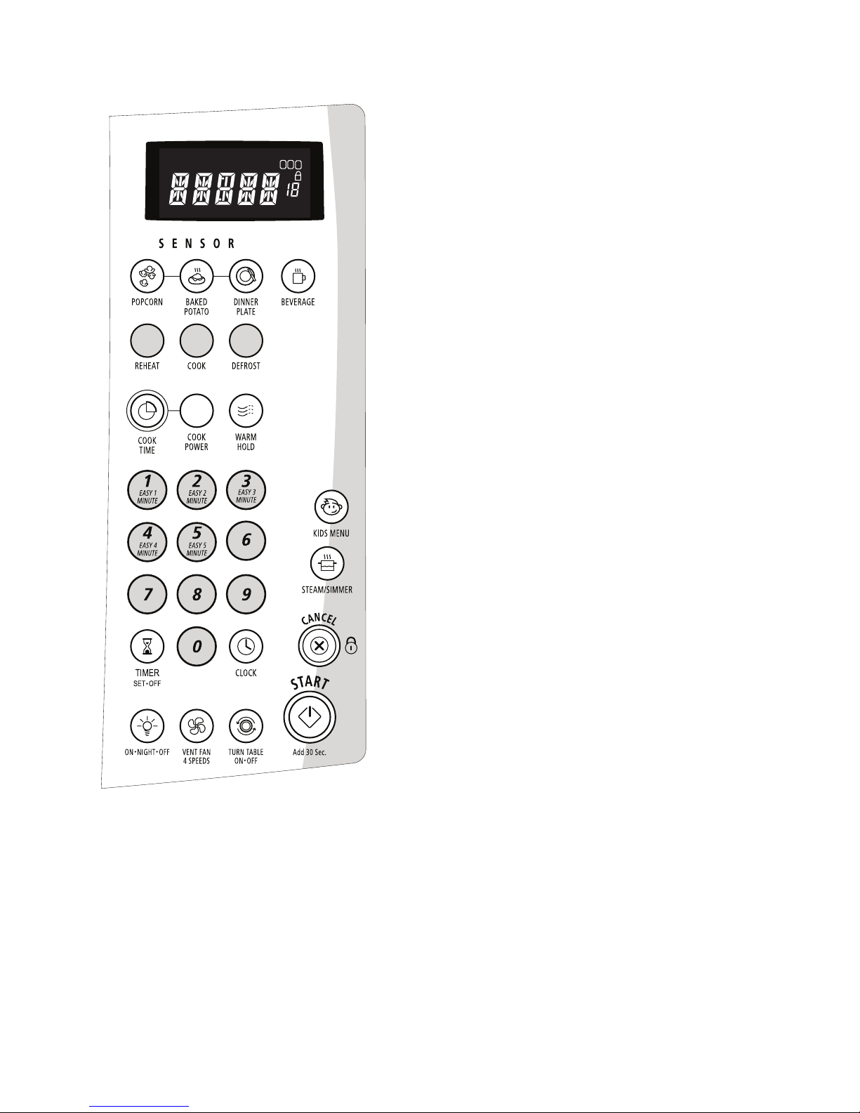
MICROWAVE OVEN CONTROL
1
2
3
When the microwave oven is in use, the display shows cooking power, quantities, weights
and/or prompts. When the microwave oven is
not in use, the display shows the time of day
or Timer countdown.
Number Codes
The microwave oven is preset with shortcut
number codes. A number code includes one or
more of the following: cooking power, cook time
and food quantity or weight. See the charts in
the “Cooking” and/or “Reheating” sections for
additional information.
Start/Add 30 Seconds
The START control shares function with the Add
30 Seconds feature. The START pad will start
any function. If not touched within 5 seconds
after touching a pad, “START?” will appear on
the display as a reminder. If not touched within
5 minutes after touching a pad, the display will
return to the time of day mode and the programmed function will be canceled.
If cooking is interrupted, touching the START
will resume the preset cycle.
DISPLAY
When power is rst supplied to the microwave
oven, a “:” will blink in the display. Touch (Cancel) to stop the blinking. If the “:” blinks in the
display at any other time, a power failure has
occurred. Touch (Cancel) and reset the clock
if needed.
If “RETRY” blinks in the display for 1 second,
an invalid value has been entered. Retry your
entry.
The ADD 30 SEC. control starts the oven at
100% power for 30 seconds, and adds 30 seconds of cook time with each additional touch
of the control. Once cooking begins, cook
power or cook time may be changed manually
by touching the appropriate display area and
entering the new setting.
Easy Minute Feature
The numerical pads 1-5 share function with
the Easy Minute controls. When one of these
controls is touched (while no function is operating), the oven will begin cooking at high power
for 1-5 minutes, depending on which pad is
touched. After cooking begins, the Easy Minute
controls return to their normal numerical pad
function.
Cancel
The CANCEL pad stops most functions except
for the Timer, Child Lock and Demo Mode.
The microwave oven will also turn off when
the door is opened. Close the door and touch
START control to resume the cycle. A sensor
3-2

cooking cycle may not be resumed if interrupted
by opening the door.
Clock
This is a standard 12-hour clock (12:0011:59) and does not show a.m. or p.m.
To Set:
The microwave oven and timer must be off.
1. Touch Clock.
2. Touch the number pads to set the time of
day.
3. Touch Clock or START.
To Remove:
1. Touch Clock.
2. Touch 0.
3. Touch Clock.
The time will disappear, and “:” will appear on
the display.
TONES
Tones are audible signals, indicating the
following:
One tone
Valid entry (short tone)•
End-of-Timer countdown (long tone)•
Two tones
Reminder, repeating each minute after the •
end-of-cycle tones
End of stage in multistage cooking•
Hidden feature has been entered or exited•
Three tones
Invalid entry•
Four tones
End of cycle•
To Turn Off Valid Entry Tones: Touch and
hold the number pad “1” for 5 seconds until two
tones sound. Repeat to turn tones back on.
To Turn Off All Tones (except End-of-Timer
and hidden feature signals): Touch and hold
the number pad “2” for 5 seconds until two
tones sound. Repeat to turn tones back on.
TIMER
The Timer can be set in minutes and seconds,
up to 99 minutes 99 seconds, and counts down
the set time.
NOTE: The Timer does not start or stop the
microwave oven. When the Timer is in use, the
microwave oven can also operate.To see the
countdown for 5 seconds when the microwave
oven is in use, touch TIMER SET-OFF.
To Set:
1. Touch Timer.
If no action is taken after 1 minute, the dis-
play will return to the time-of-day mode.
2. Touch the number pads to set the length
of time.
3. Touch Timer or START.
If Timer or START is not touched within
5 seconds, “START?” will appear in the
display. If Timer or START is not touched
within one minute, the display will return to
the time-of-day mode and the programmed
function will be canceled.
When the set time ends, “END” will appear
in the display and one tone will sound.
Touching OFF while a cook function is
active in the display will cancel the cook
function, not the Timer.
To cancel the Timer, touch TIMER or OFF while
the countdown is active in the display.
The length of time can be changed during the
countdown by repeating the above steps.
Child Lock
The Child Lock shuts down the control panel
pads to prevent unintended use of the microwave oven.
When the control is locked, only the Vent Fan
and Light pads will function.
To Lock/Unlock Control: The microwave
oven and Timer must be off. Touch and hold
CANCEL for 5 seconds until 2 tones sound and
a lock icon appears on the display. Repeat to
unlock and remove the lock icon from display.
3-3
 Loading...