

Whirlpool WED9500E, MEDB955F, MGDB955F, WGD9500E Service Manual
Multimedia
Enhanced
L-91
SERVICE MANUAL
WHIRLPOOL & MAYTAG
9.2 CU. FT. STEAM DRYER
WED9500E*, WGD9500E* MEDB955F*, MGDB955F*
*All Colors & Versions
W10881701

FORWARD
This Whirlpool Service Manual, (Part No. W10881701), provides the In-Home Service Professional with
service informaon for the “WHIRLPOOL & MAYTAG 9.2 CU. FT. STEAM DRYER.”
The Wiring Diagram used in this Service Manual is typical and should be used for training purposes
only. Always use the Wiring Diagram supplied with the product tech sheet when servicing the dryer.
For specic operang and installaon informaon on the model being serviced, refer to the “Use and
Care Guide” or “Installaon Instrucons” provided with the dryer.
GOALS AND OBJECTIVES
The goal of this Service Manual is to provide informaon that will enable the In-Home Service
Professional to properly diagnose malfuncons and repair the “WHIRLPOOL & MAYTAG 9.2 CU. FT.
STEAM DRYER.”
The objecves of this Service Manual are to:
• Understand and follow proper safety precauons.
• Successfully troubleshoot and diagnose malfuncons.
• Successfully perform necessary repairs.
• Successfully return the washer to its proper operaonal status.
WHIRLPOOL CORPORATION assumes no responsibility for any repairs made on our
products by anyone other than authorized In-Home Service Professionals.
Copyright © 2016, Whirlpool Corporaon, Benton Harbor, MI 49022
ii
Whirlpool & Maytag 9.2 Cu. Ft. Steam Dryer
n

TABLE OF CONTENTS
WHIRLPOOL & MAYTAG 9.2 CU. FT. STEAM DRYER
SECTION 1 — GENERAL INFORMATION
WASHER SAFETY .................................................................................................................................1-2
GENERAL INFORMATION ...................................................................................................................1-3
MODEL & SERIAL NUMBER LABEL LOCATION....................................................................................1-4
TECH SHEET LOCATION .......................................................................................................................1-4
MODEL AND SERIAL NUMBER NOMENCLATURE ..............................................................................1-5
PRODUCT SPECIFICATIONS ................................................................................................................1-6
SECTION 2 — DIAGNOSTICS & TROUBLESHOOTING
WHIRLPOOL CONTROL PANEL ............................................................................................................2-2
MAYTAG CONTROL PANEL ..................................................................................................................2-3
DIAGNOSTIC GUIDE ............................................................................................................................2-4
SERVICE DIAGNOSTIC MODE .............................................................................................................2-4
ACTIVATING SERVICE DIAGNOSTIC MODE ........................................................................................2-4
KEY ACTIVATION & ENCODER TEST ....................................................................................................2-5
SERVICE TEST MODE...........................................................................................................................2-5
SERVICE TEST MODE CHART ..............................................................................................................2-5
SOFTWARE VERSION DISPLAY ............................................................................................................2-7
FAULT/ERROR CODES..........................................................................................................................2-7
EXITING SERVICE DIAGNOSTIC MODE ...............................................................................................2-7
CUSTOMER FAULT/ERROR CODES CHART ..........................................................................................2-7
SERVICE FAULT/ERROR CODES CHART ...............................................................................................2-8
TROUBLESHOOTING GUIDE .............................................................................................................2-10
NOTES ...............................................................................................................................................2-12
SECTION 3 — COMPONENT TESTING
COMPONENT TESTING: SAFETY INFORMATION ................................................................................3-2
COMPONENT LOCATIONS ..................................................................................................................3-3
WIRING DIAGRAM - ELECTRIC ...........................................................................................................3-4
WIRING DIAGRAM - GAS ....................................................................................................................3-5
COMPONENT TESTING .......................................................................................................................3-6
TEST #1: ACU POWER CHECK ..............................................................................................................3-6
ACU BOARD / CONNECTORS & PINOUTS ...........................................................................................3-7
TEST #2: SUPPLY CONNECTIONS ........................................................................................................3-8
TEST #3: MOTOR CIRCUIT .................................................................................................................3-10
TEST #4: HEAT SYSTEM .....................................................................................................................3-12
TEST #4A: THERMISTORS ..................................................................................................................3-14
TEST #4B: THERMAL FUSE ................................................................................................................3-15
TEST #4C: THERMAL CUTOFF ............................................................................................................3-15
TEST #4D: GAS VALVE .......................................................................................................................3-16
TEST #5: MOISTURE SENSOR ............................................................................................................3-17
TEST #5A: ADJUSTING CUSTOMER-FOCUSED DRYNESS LEVEL........................................................3-18
TEST #6: BUTTONS AND INDICATORS ..............................................................................................3-19
TEST #7: DOOR SWITCH ....................................................................................................................3-20
TEST #8: DRUM LED ..........................................................................................................................3-21
TEST #9: WATER VALVE .....................................................................................................................3-22
TEST #10: SERVICE LEDS ...................................................................................................................3-23
NOTES ...............................................................................................................................................3-24
Whirlpool & Maytag 9.2 Cu. Ft. Steam Dryer
n
iii

SECTION 4 — COMPONENT ACCESS
COMPONENT LOCATIONS ..................................................................................................................4-2
REMOVING THE DOOR ASSEMBLY* ...................................................................................................4-3
REMOVING THE TOP PANEL* .............................................................................................................4-4
REMOVING THE USER INTERFACE* ....................................................................................................4-4
REMOVING THE APPLIANCE CONTROL UNIT (ACU)* ........................................................................4.5
REMOVING THE FRONT PANEL & DOOR SWITCH* ............................................................................4-6
REMOVING THE DRUM LIGHT* ..........................................................................................................4-7
REMOVING THE MOISTURE SENSOR* ...............................................................................................4-7
REMOVING THE BELT, DRUM, AND ROLLERS* ...................................................................................4-8
REMOVING THE DRIVE MOTOR* .....................................................................................................4-10
REMOVING THE THERMAL FUSE & OUTLET THERMISTOR (ELECTRIC)* .........................................4-11
REMOVING THE HEATER ELEMENT (ELECTRIC)* ..............................................................................4-12
REMOVING THE HIGH LIMIT THERMOSTAT & THERMAL CUTOFF (ELECTRIC)* ..............................4-12
REMOVING THE IGNITOR, FLAME SENSOR (GAS)............................................................................4-13
REMOVING THE HIGH-LIMIT THERMOSTAT & THERMAL CUTOFF (GAS) ........................................4-13
REMOVING THE GAS BURNER ASSEMBLY COILS (GAS) ...................................................................4-15
REMOVING THE WATER VALVE* ......................................................................................................4-16
* Video Available Look for this ICON throughout Secon 4
PRODUCT SPECIFICATIONS & WARRANTY INFORMATION SOURCES (inside back cover)
iv
Whirlpool & Maytag 9.2 Cu. Ft. Steam Dryer
n

GENERAL INFORMATION
Section 1:
General Information
This secon provides general safety, parts, and informaon for
the “Whirlpool & Maytag 9.2 Cu. Ft. Steam Dryer.”
n Dryer Safety
n General Info
n Model/Serial Number Locaon
n Tech Sheet Locaon
n Model & Serial Number Nomenclature
n Product Specicaons
Whirlpool & Maytag 9.2 Cu. Ft. Steam Dryer
n
1-1
GENERAL INFORMATION
Dryer Safety
Your safety and the safety of others are very important.
We have provided many important safety messages in this manual and on your appliance. Always read and obey all safety
messages.
This is the safety alert symbol.
This symbol alerts you to potential hazards that can kill or hurt you and others.
All safety messages will follow the safety alert symbol and either the word “DANGER” or “WARNING.”
These words mean:
You can be killed or seriously injured if you don't immediately
DANGER
WARNING
All safety messages will tell you what the potential hazard is, tell you how to reduce the chance of injury, and tell you what can
happen if the instructions are not followed.
follow instructions.
You
can be killed or seriously injured if you don't
instructions.
follow
1-2
Whirlpool & Maytag 9.2 Cu. Ft. Steam Dryer
n
GENERAL INFORMATION
General Info
INTRODUCTION
The new Whirlpool and Maytag Steam Dryers represents
industry-leading innovaon with Advanced Moisture Sensing
using three sensors to track moisture and temperature,
adapng drying mes to end the cycle at just the right me.
NEW COMPONENTS
Sleek Under Glass User Interface — the Whirlpool dryer features a new sleek under glass capacive touch user interface that
asks “what’s being dried” followed by “how you want to dry.” First select a cycle from the “What to Dry” (Casuals, Jeans, Towels,
Delicates, AcveWear, and Bulky Sheets) and then select the “How to Dry” (Normal, Gentle, Sanize, Quick, Timed Dry, Steam
Refresh). This new and improved input will help the customer achieve the best combinaon cycle available for the type of items
being dried.
Addional features include 9.2 cu. . capacity, Stainless Steel
Drum, Intuive Touch Controls with Memory, Customized
Fabric Care, and a Steam Refresh Cycle that releases wrinkles
and reduces odors without rewashing.
What to Dry
Figure 1 - User Interface with Intuitive Touch Controls
Extra Large 9.2 cu. . Capacity Drum — Our largest dryer
opening available, the Whirlpool and Maytag dryers have an
extra large drum capacity of 9.2 cu.. The drum’s stainless
steel construcon presents a smooth surface that helps deliver
ulmate gentleness, cradling clothes as they tumble.
How to Dry
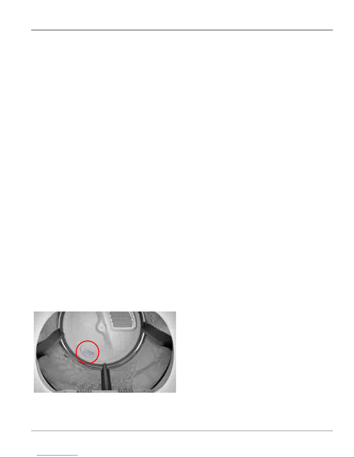
Advanced Moisture Sensing — now using up to four (4)
moisture sensors to track moisture more accurately. Two
moisture sensors in the front of the dryer, located on the lint
screen outlet grill, (see Figure 3 below) and on Maytag models,
two moisture sensors in the back of the dryer, located on the
rear bulkhead, (circled in Figure 2).
Figure 2 - Extra Large Capacity Basket
Figure 3 - Moisture Sensors
Whirlpool & Maytag 9.2 Cu. Ft. Steam Dryer
n
1-3

GENERAL INFORMATION
Model & Serial Number Location
Model & Serial Number
Label Location
Figure 3 - Model / Serial Number
Tech Sheet Location
Tech Sheet Location (Under CCU)
(Whirlpool) Beneath Top Panel
CCU
(Maytag) Beneath Console
1-4
Whirlpool & Maytag 9.2 Cu. Ft. Steam Dryer
n
Figure 4 - Tech Sheet Location

GENERAL INFORMATION
Model & Serial Number Nomenclature
MODEL NUMBER W E
INTERNATIONAL SALES OR
MARKETING CHANNEL
BRAND
W = Whirlpool; M = Maytag
ACCESS
E = Electric Dryer; G = Gas Dryer
PRODUCT
W = Washer; D = Dryer
FEATURE SET
9500 = Whirlpool 9.2 Cu. Ft.
B955 = Maytag 9.2 Cu. Ft.
YEAR OF INTRODUCTION
E = 2015; F = 2016
COLOR CODE
W = White; C = Chrome Shadow
D
9500 E W 0
ENGINEERING CHANGE
0 = Basic Release; 1 = First Revision
SERIAL NUMBER M 4 25 10000
PRODUCTION SITE
M = MARION, OH
YEAR OF PRODUCTION
4 = 2014; 5 = 2015
WEEK OF PRODUCTION
PRODUCT SEQUENCE NUMBER
Whirlpool & Maytag 9.2 Cu. Ft. Steam Dryer
n
1-5
GENERAL INFORMATION
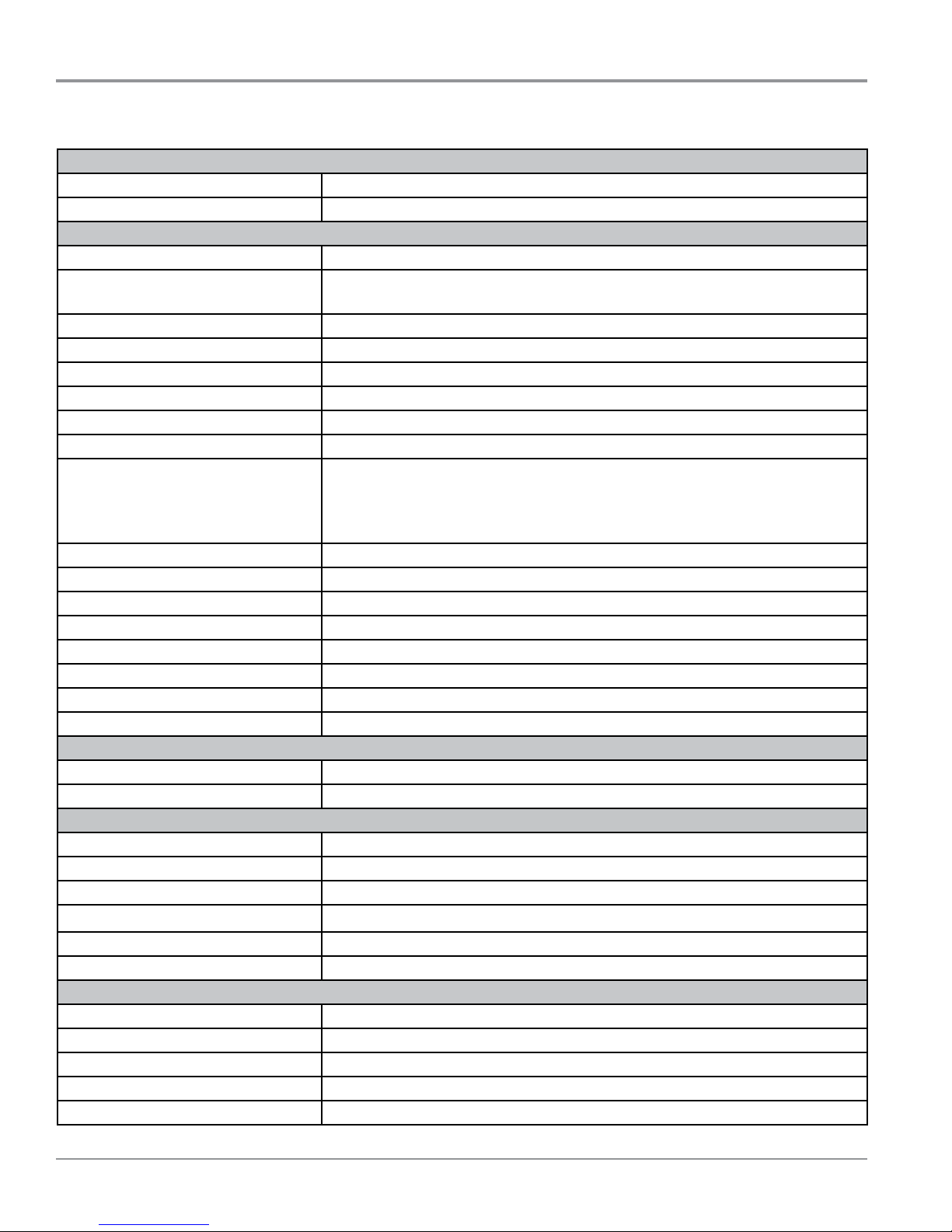
Product Specifications
ELECTRICAL
Fuel Type (Electric) : 240 VAC, 60 Hz, 30 Amp Service
Fuel Type (Gas) : 120 VAC, 60 Hz, 15-20 Amp Service
PRIMARY FEATURES
Capacity : 9.2 cu. .
Control Panel : (Whirlpool) Front / Capacive Touch / Electronic
(Maytag) Rear Panel / Capacive Touch / Cycle Select Knob
Drum Material : Stainless Steel
Drum Design : Quad Baes
Door Style : Side Swing, Reversible, Window
Interior Light : Yes
Energy Star® Qualied : Yes
Steam : Yes
Cycles (Whirlpool) : (What to Dry)
Mixed, Casuals, Jeans, Towels, Delicates, AcveWear, Bulky/Sheets
(How to Dry)
Normal, Gentle, Sanize, Quick, Timed Dry, Steam Refresh
Temperatures : (5) Air Only, Extra Low, Low, Medium, High
Dryness Levels : (4) Less, Low, Medium, More
Lint Filter Indicator : Yes
Automac Dry Control : Yes
EcoBoost™ Energy Saver Yes
Cycle Time Remaining : Yes
Advanced Moisture Sensor : Yes
Sound Package : Yes
INSTALLATION CONSIDERATIONS
Venng Direcon : 4-Way (Le, Right, Boom, Rear)
Maximum Vent Length : 64 .
OPTIONS
Audio Level : Change the sounds from low, medium, high, or o
End of Cycle Signal : Sound when cycle is complete
Damp Dry Signal : Sound when load is damp, but not completely dry
Eco Boost™ : Use a slightly lower heat level to increase energy savings
Stac Reduce : Introduces a small amount of moisture to reduce stac
Wrinkle Shield™ with Steam : Adds up to 150 minutes of periodic tumbling to reduce wrinkling
DIMENSIONS
Height : 41 3/8” (105.1 cm)
Width : 29” (73.66 cm)
Depth : 33 1/2” (85.1 cm)
Depth with door open : 57 5/8” (146.4 cm)
Gross Weight : 191 lbs. (86.64 kg)
1-6
Whirlpool & Maytag 9.2 Cu. Ft. Steam Dryer
n

DIAGNOSTICS & TROUBLESHOOTING
Section 2:
Diagnostics &
Troubleshooting
This secon provides diagnosc, fault codes, and
troubleshoong informaon for the “Whirlpool & Maytag 9.2
Cu. Ft. Steam Dryer.”
n Whirlpool Control Panel
n Maytag Control Panel
n Diagnosc Guide
n Service Diagnosc Mode
n Acvang Service Diagnosc Mode
n Key Acvaon & Encoder Test
n Service Test Mode
n Soware Version Display
n Exing Service Diagnosc Mode
n Fault/Error Codes
n Customer Fault/Error Codes
n Service Fault/Error Codes
n Troubleshoong Guide
n Notes
Whirlpool & Maytag 9.2 Cu. Ft. Steam Dryer
n
2-1
DIAGNOSTICS & TROUBLESHOOTING
FOR SERVICE TECHNICIAN’S USE ONLY
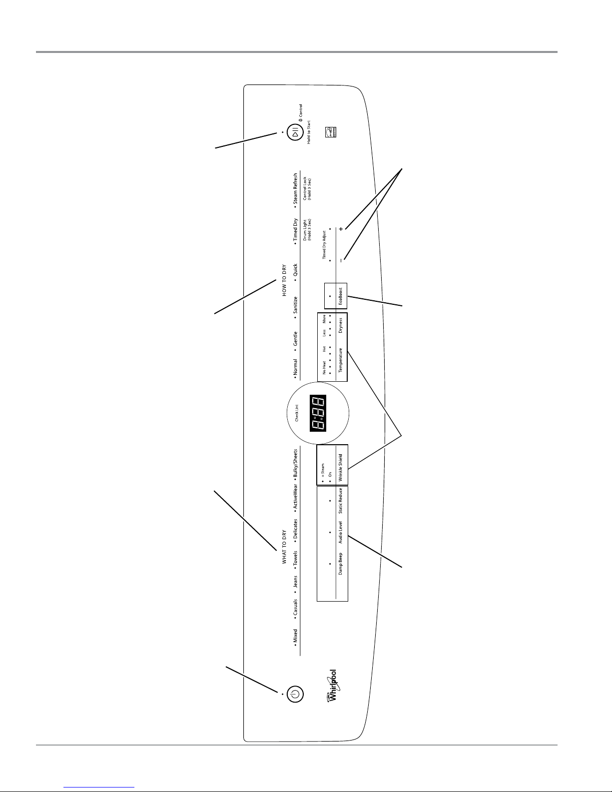
Figure 1 - Key Activation & Encoder Test for Service Diagnostic Mode
For Service Technician Use Only
off “Control” indicator).
to turn off indicator (also turns
START/PAUSE button: press once
its respective indicator.
Timed Dry Adjust “–” or “+”
button: press once to turn off
“Check Lint” display.
Pressing each “HOW TO DRY”
button turns off each corresponding
off the seven-segment display and the
indicator. Pressing “Normal” also turns
the light ring LEDs.
Pressing “Bulky/Sheets” also turns off
Pressing each “WHAT TO DRY” button
turns off each corresponding indicator.
button once to turn off
its respective indicator.
Option buttons: press each
display segment.
Press each modifier button
once to turn off its respective
button once to turn off
its respective indicator.
Option buttons: press each
indicator. Press twice to exit service
Whirlpool Control Panel (features and appearances may vary between models)
2-2
Whirlpool & Maytag 9.2 Cu. Ft. Steam Dryer
n
POWER button: press once to turn off
standby mode.
diagnostic mode and return to
Figure 1 - Key Activation & Encoder Test for Service Diagnostic Mode
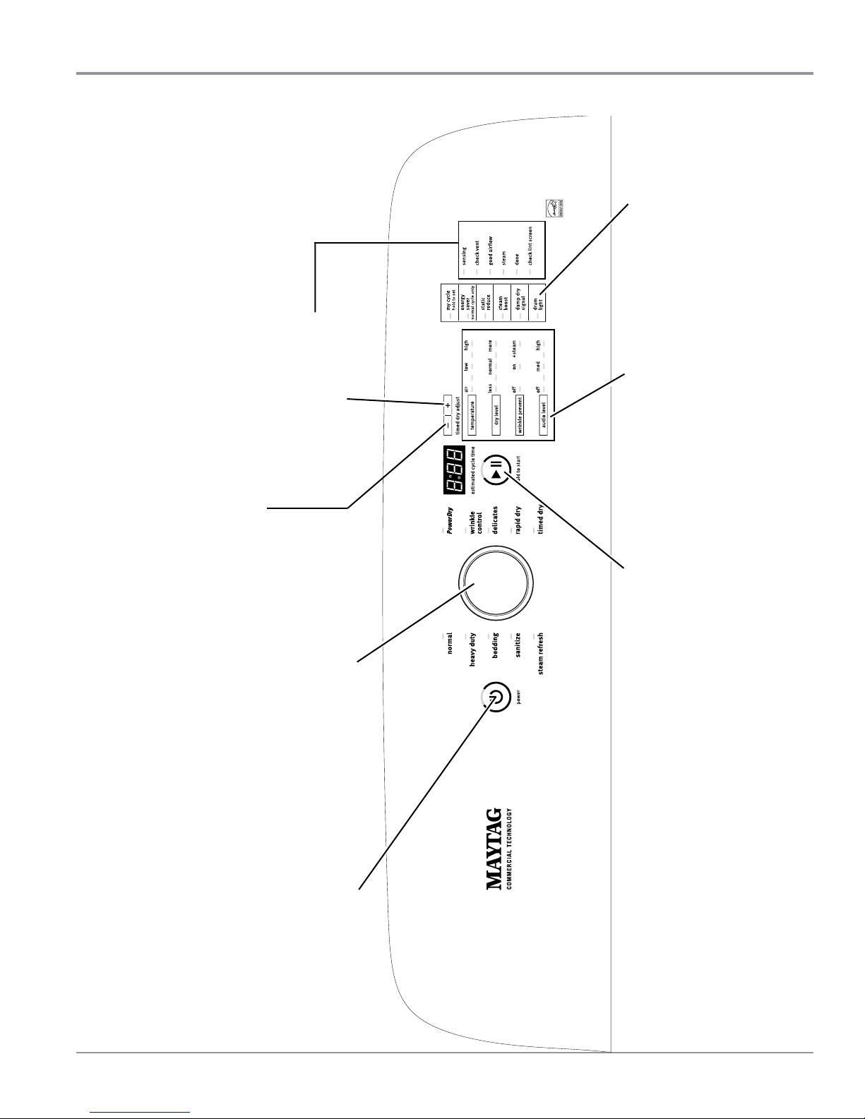
For Service Technician Use Only
FOR SERVICE TECHNICIAN’S USE ONLY
DIAGNOSTICS & TROUBLESHOOTING
button once to turn off
its respective indicator.
Option buttons: press each
press once to turn off the
Timed Dry Adjust “+” button:
seven-segment display.
press once to turn off the
Timed Dry Adjust “–” button:
indicator. (Features and
Rotating the cycle selector knob
turns off each corresponding cycle
status LEDs.
appearances vary between models).
display segment.
Press each modifier button
once to turn off its respective
off indicator.
press once to turn
START/PAUSE button:
Maytag Control Panel (features and appearances may vary between models)
to standby mode.
off indicator. Press twice to exit
POWER button: press once to turn
service diagnostic mode and return
Whirlpool & Maytag 9.2 Cu. Ft. Steam Dryer
n
2-3
Figure 2 - Key Activation & Encoder Test for Service Diagnostic Mode
FOR SERVICE TECHNICIAN’S USE ONLY
tripped? Was a regular fuse used? Inform
customer that a time-delay fuse is required.
Is dryer vent properly installed and clear
of lint or obstructions?
VOM (volt-ohm-milliammeter) or DVM
(digital-voltmeter) having a sensitivity of
20,000 1 per volt DC or greater.
dryer unplugged or power disconnected.
diameter probes when checking harness
connectors as the probes may damage
the connectors upon insertion.
before replacing components. Look for
connectors not fully seated, broken or
loose wires and terminals, pin insertion,
or wires not pressed into connectors
far enough to engage metal barbs.
functioning is corrosion or contamination on
connections. Use an ohmmeter to check for
continuity across suspected connections.
SERVICE DIAGNOSTIC MODE
These tests allow service personnel to test
and verify all inputs to the machine control
electronics. You may want to do a quick and
overall checkup of the dryer with these tests
before going to specific troubleshooting tests.
ACTIVATING SERVICE DIAGNOSTIC MODE
1. Be sure the dryer is in standby mode
(plugged in with all indicators off).
2. Select any three (3) buttons (except
POWER) and follow the steps below, using
the same buttons (remember the buttons and
the order that the buttons were pressed):
Within 8 seconds,
• Press and Release the 1st selected button,
• Press and Release the 2nd selected button,
• Press and Release the 3rd selected button;
• Repeat this 3 button sequence 2 more times.
3. If this test mode has been entered
successfully, all indicators on the console
will be illuminated for 5 seconds with “”
showing in the three-digit display and a tone
will sound. If there are no saved fault codes,
all indicators on the console will turn off,
and only the seven segment display will
remain on.
NOTE: The Service Diagnostic mode will time
out after 10 minutes of user inactivity, or shut
down if AC power is removed from the dryer.
DIAGNOSTICS & TROUBLESHOOTING
For Service Technician Use Only
Diagnosc Guide
Before servicing, check the following:
n Make sure there is power at the wall outlet.
n Make sure control lock is not enabled.
n Has a household fuse blown or circuit breaker tripped? Was
a regular fuse used? Inform customer that a me-delay
fuse is required.
n Is dryer vent properly installed and clear of lint or
obstrucons?
n All tests/checks should be made with a VOM (volt-
ohm-milliammeter) or DVM (digital-voltmeter) having a
sensivity of 20,000 Ω per volt DC or greater.
n Resistance checks must be made with dryer unplugged or
power disconnected.
n IMPORTANT: Avoid using large diameter probes when
checking harness connectors as the probes may damage
the connectors upon inseron.
n Check all harnesses and connecons before replacing
components. Look for connectors not fully seated, broken
or loose wires and terminals, pin inseron, or wires not
pressed into connectors far enough to engage metal barbs.
n A potenal cause of a control not funconing is corrosion
or contaminaon on connecons. Use an ohmmeter to
check for connuity across suspected connecons.
Service Diagnosc Mode
These tests allow service personnel to test and verify all inputs
to the machine control electronics. You may want to do a quick
and overall checkup of the dryer with these tests before going
to specic troubleshoong tests.
Acvang Service Diagnosc Mode
1. Be sure the dryer is in standby mode (plugged in with all
indicators o).
2. Select any three (3) buons (except POWER) and follow
the steps below, using the same buons (remember the
buons and the order that the buons were pressed):
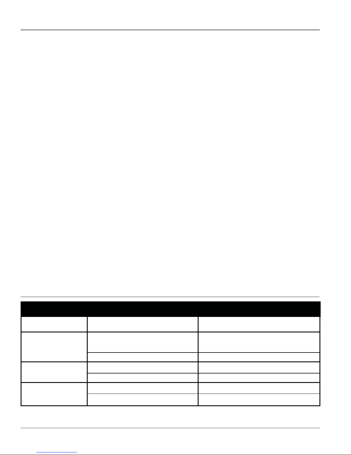
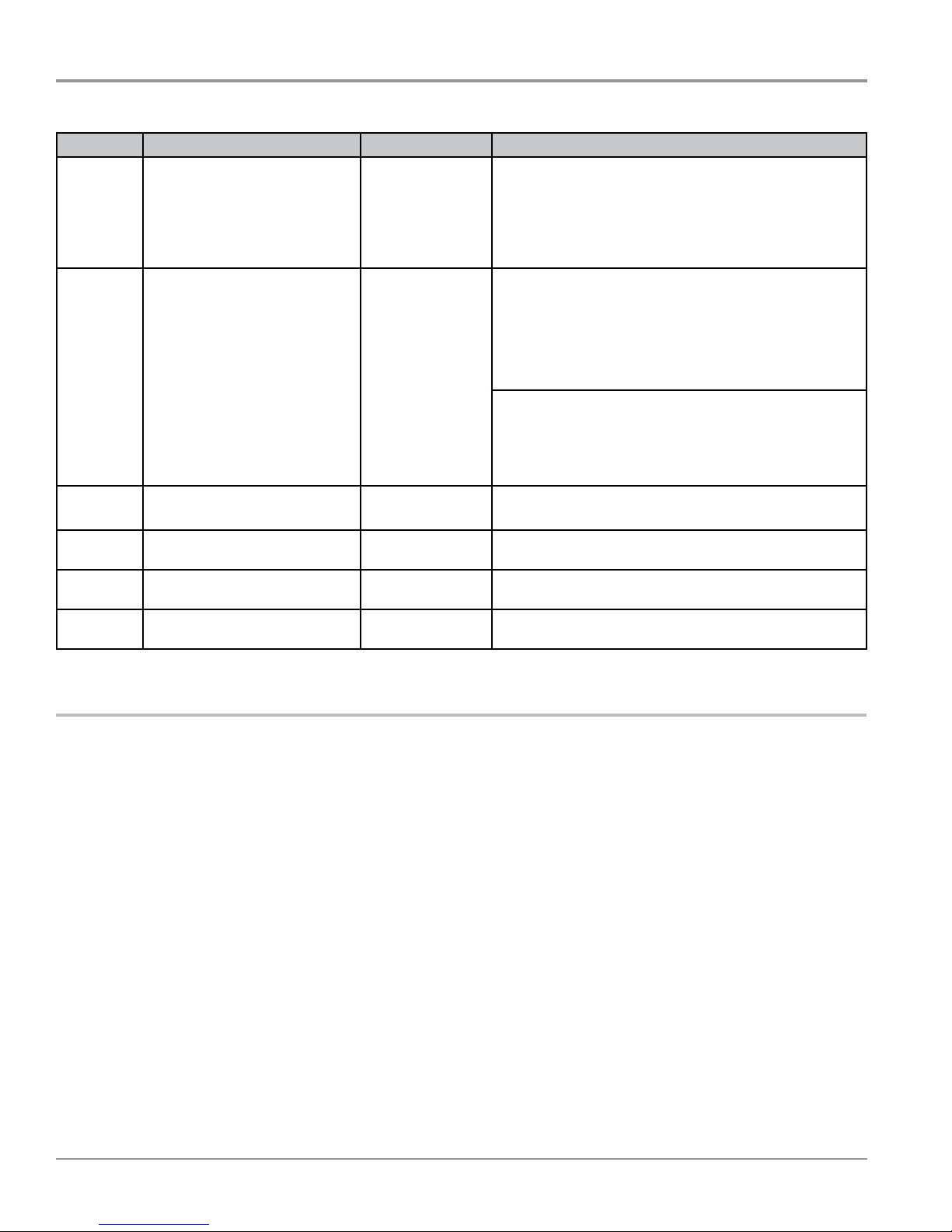
SERVICE DIAGNOSTIC MENU TABLE
Button Press Function Behavior
Within 8 seconds,
• Press and Release the 1st selected buon,
• Press and Release the 2nd selected buon,
• Press and Release the 3rd selected buon;
• Repeat this 3 buon sequence 2 more mes.
3. If this test mode has been entered successfully, all
indicators on the console will be illuminated for 5 seconds
with “888” showing in the three-digit display and a tone
will sound. If there are no saved fault codes, all indicators
on the console will turn o, and only the seven segment
display will remain on.
NOTE: The Service Diagnosc mode will me out aer
10 minutes of user inacvity, or shut down if AC power is
removed from the dryer.
Unsuccessful Activation
If entry into diagnosc mode is unsuccessful, refer to the
following indicaons and acons:
Indicaon 1: None of the indicators or display turn on.
Acon: Select any cycle.
¾ If indicators come on, try to change the funcon for the
three buons used to acvate the diagnosc test mode. If
any buon is unable to change the funcon, something is
faulty with the buon, and it will not be possible to enter
the diagnosc mode using that buon. Replace the user
interface and housing assembly.
¾ If no indicators come on aer selecng the cycle, go to
TEST #1, ACU Power Check, page 3-6.
Indicaon 2: Console indicators begin ashing immediately.
Acon: If console indicators begin ashing on and o
immediately, replace the user interface.
Acvaon with Saved Fault Codes
If there is a saved fault code, it will be ashing in the display.
Review the Fault/Error Codes table on page 2-8 for the
recommended procedure. If there is no saved fault code,
“888” will be displayed.
1st Button - Momentary press
- Press and hold for 5 secs.
2nd Button - Momentary press
- Press and hold for 5 secs.
3rd Button - Momentary press
- Press and hold for 5 secs.
• See “Acvang Service Diagnosc Mode” to acvate these buons. Make sure all of step 3 is complete before acvaon.
2-4
Whirlpool & Maytag 9.2 Cu. Ft. Steam Dryer
n
- Activates Key Activation
& Encoder Test
- Exits Service Diagnostics
- Activates Service Test Mode
- Software Version Display
- Displays Next Error Code
- Clears the Error Codes
DIAGNOSTICS & TROUBLESHOOTING
For Service Technician Use Only
KEY ACTIVATION & ENCODER TEST
NOTE: The Service Diagnosc mode must be acvated before
entering the Key Acvaon & Encoder Test; see procedure on
page 2-4.
Acve Fault Code Display In Key Acvaon & Encoder Test
If the display begins ashing while in the Key Acvaon &
Encoder Test, it is displaying an acve fault code. Acve fault
codes are codes that are currently detected. Only one acve
fault code can be displayed at a me.
Entry Procedure
Press and release the 1st buon used to acvate Service
Diagnosc mode. The following test will be available:
DIAGNOSTIC: Key Activation & Encoder Test
Pressing each buon will turn o its corresponding indicator(s)
or display segment and sound a beep (see gure 1 & 2, pages
2-2 and 2-3.)
Rotang the cycle selector knob (on some models) turns o
each corresponding cycle indicator.
NOTE: A second press of the POWER buon while in Key
Acvaon & Encoder Test mode exits the Service Diagnosc
mode and returns the dryer to standby mode.
¾ If indicators do not turn o and beep aer pressing buons
and rotang the cycle selector knob (on some models), go
to TEST #6: Buons and Indicators, page 3-19.
Exit Procedure
To exit Key Acvaon & Encoder Test, press the POWER buon
once or twice (depending on diagnosc procedure) or press and
hold the rst buon used to acvate Service Diagnosc mode.
SERVICE TEST MODE
NOTE: The Service Diagnosc mode must be acvated before
entering Service Test Mode; see procedure on page 2-4.
NOTE: If, at any point, the user presses the POWER buon or
opens the door during Service Test Mode, the dryer exits to
standby mode.
NOTE: Door must be closed to perform test. Dryer must be
cool before test to run correctly.
Acve Fault Code Display in Service Test Mode
If the display begins ashing while in Service Test Mode, it is
displaying an acve fault code. Acve fault codes are codes
that are currently detected. Only one acve fault code can be
displayed at a me.
Entry Procedure
To enter Service Test Mode, press and release the 2nd buon
used to acvate the Service Diagnosc mode. All LEDs (except
for POWER) turn o, “888” is displayed for 2 seconds, and the
START buon begins to ash.
PERFORM ALL TESTS: Press and release the START buon to
run ALL tests indicated in the chart below and on page 2-6.
VOLTAGE AND WATER SYSTEM-ONLY TESTS: Press and hold
the START buon for 5 seconds aer step 3 to run only the
voltage and water system tests.
Exit Procedure
When the test is complete, press the POWER buon to exit
Service Test Mode and return to standby mode.
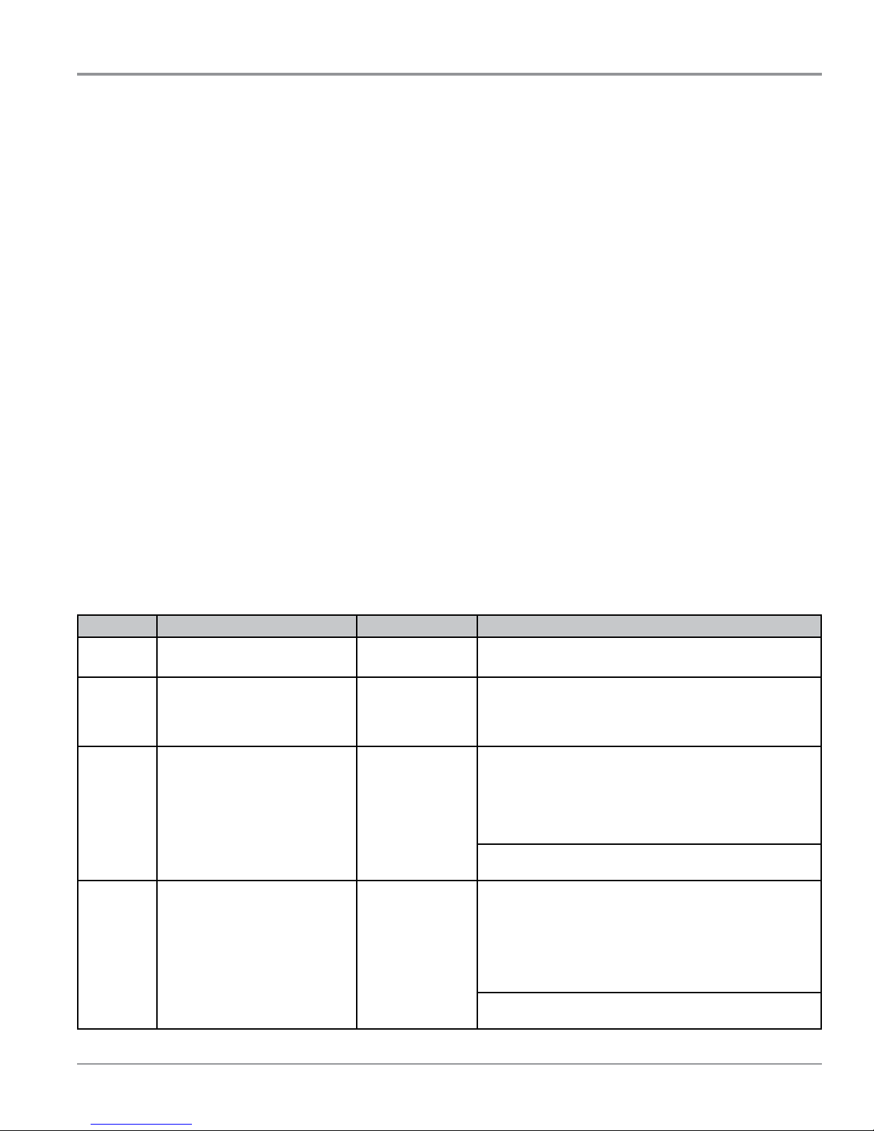
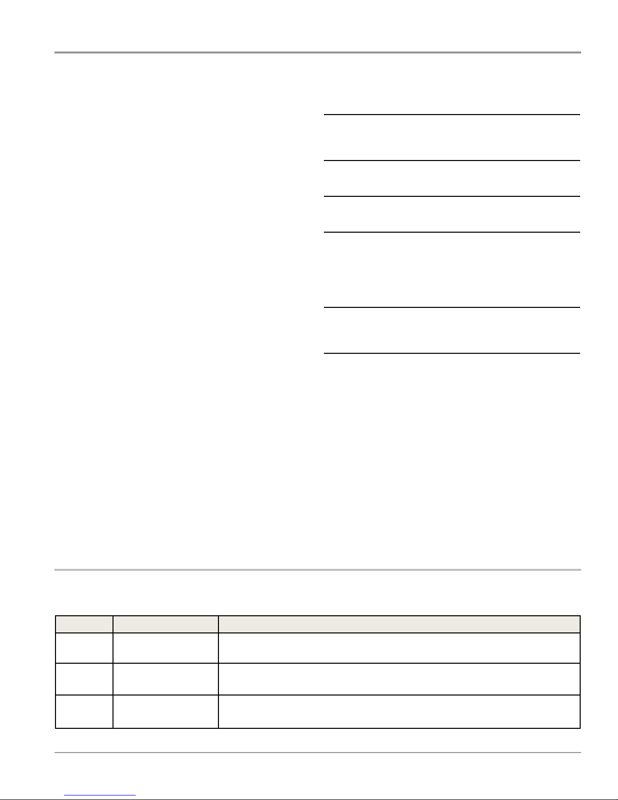
SERVICE TEST MODE CHART
Step # Action Component User Interface Response
1 User enters Service Test Mode
through Service Diagnoscs.
2 Press and release START to
begin the L2 Voltage Check.
3 L2 Voltage Check completes.
Vrms_L2 and Fuel are published
to the UI.
L1 Voltage Check starts
automacally.
4 L1 Voltage Check completes.
Vrms_L1 and Heater_Voltage
are published to the UI.
Check for Warm Machine begins
automacally. Airow begins
detecon algorithm: Status_
Airow = 3 (Detecng).
Press and hold START to jump to
Step 8 and start the Steam Test.
Motor On The display will show “----” unl the voltage is available
Motor On
Heater(s) On
Motor On
Heater(s) On/O
Display shows “888” for 2 seconds. All LEDs (except for
POWER) are o, and the START buon is ashing.
at the UI.
If the START is pressed again or pressed and held before
L2 voltage is available, a tone will sound 3 mes.
If electric (Fuel = Electric): The UI will report ndings
per the “Electric Dryer Results Display” secon where L2
Voltage is available, L1 Voltage is not available, Heater
Voltage is not available, and Airow is not available.
If gas (Fuel = Gas): The display will connue to show
“----”.
If START is pressed again or pressed and held before L1
voltage is available, a tone will sound 3 mes.
If electric (Fuel = Electric): The UI will report ndings
per the “Electric Dryer Results Display” secon where
L2 Voltage is available, L1 Voltage is available, Heater
Voltage is available, and Airow is not available.
If gas (Fuel = Gas): The UI will report ndings per the
“Gas Dryer Results Display” secon where Heater Voltage
is available and Airow is not available.
If a “Detecng Airow” indicator is present, it is displayed
on the UI.
Connued on next page...
Whirlpool & Maytag 9.2 Cu. Ft. Steam Dryer
n
2-5
DIAGNOSTICS & TROUBLESHOOTING
For Service Technician Use Only
Step # Action Component User Interface Response
5 Check for Warm Machine
completes.
Load Mass for Airow begins
automacally.
Press and hold START to jump to
Step 8 and start the Steam Test.
6 Load Mass for Airow
completes. The update for
Status_Airow is published to
the UI.
7 Service Loads Test Complete. Motor O
8 Pressing START begins
STEAM_TEST.
9 Steam Test begins. Water Valve On
10 STEAM_TEST complete. Water Valve O
NOTE: Aer step 3, press and hold the START buon for 5 seconds to jump to the water system test.
Electric dryer performance is opmized for 2-phase, 240 VAC service. If complaint is made regarding electric dryer performance and the L1 to L2 voltage is ~208
VAC, dryer may be connected to a 3-phase service with reduced waage that will decrease dryer performance.
Motor On
Heater(s) On
Motor On/O
Heater(s) On/O
Heater(s) O
Drum Light On
Drum Light O
UI connues to display as in Step 4.
If electric (Fuel = Electric): The UI will report ndings
per the “Electric Dryer Results Display” secon where
L2 Voltage is available, L1 Voltage is available, Heater
Voltage is available, and Airow is available.
If gas (Fuel = Gas): The UI will report ndings per the
“Gas Dryer Results Display” secon where Heater Voltage
is available and Airow is available.
If a “Detecng Airow” LED is present, it is turned o.
If a “Good Airow” LED is present, it also displays when
the Status_Airow = 0.
If a “Check Vent” LED is present, it also displays when the
Status_Airow = 2.
UI & Status LEDs connue to display as in step 6.
“START” is ashing to start the Steam Test.
Display show “h2o” when test is running.
If applicable, UI turns on Drum Light LED. Drum light is
turned on for a maximum of 30 seconds.
Display goes blank and waits for “ServiceTimeout” or
pressing of POWER to go to Standby mode.
Electric Dryer Results Display
The frame rate will be 0.5 seconds per frame. This sequence
will repeat. The text will be right aligned.
Frame 1: L2
Frame 2: When the voltage is available to the UI, it will display
it without illuminang the colon (range 0 to 200).
Frame 3: L1
Frame 4: When the voltage is available to the UI, it will display
it without illuminang the colon (range 0 to 200).
Frame 5: Htr
Frame 6: When the voltage is available to the UI, it will display
it without illuminang the colon (range 0 to 200).
Frame 7: Air
Frame 8: See “Airow Display Secon”.
When the voltage or airow is not yet available to the UI, the
display will show “---”.
2-6
Whirlpool & Maytag 9.2 Cu. Ft. Steam Dryer
n
Gas Dryer Results Display
The frame rate will be 0.5 seconds per frame. This sequence
will repeat. The text will be right aligned.
Frame 1: Htr
Frame 2: When the voltage is available to the UI, it will display
it without illuminang the colon (range 0 to 200).
Frame 3: Air
Frame 4: See “Airow Display Secon”.
When the voltage or airow is not yet available to the UI, the
display will show “---”.
Airow Display:
Value Seng
0 Airow not bad
1 Cannot detect
2 Airow bad; check vent
3 (Default) Detecng
If the result is not yet available, it will be displayed as “---”.
Status_Airow = 0 will be displayed as: “000”.
Status_Airow = 1 will be displayed as: “001”.
Status_Airow = 2 will be displayed as: “002”.
Status_Airow = 3 will be displayed as: “003”.
DIAGNOSTICS & TROUBLESHOOTING
For Service Technician Use Only
SOFTWARE VERSION DISPLAY
NOTE: The Soware Version Display mode will me out aer
10 minutes of user inacvity and return to standby mode.
Entry Procedure
To enter Soware Version Display, press and hold the 2nd
buon used to acvate the Service Diagnosc mode for 5
seconds. Upon entry, the display will automacally cycle
through the following informaon:
• UI soware revision code (U: major revision number, U:
minor revision number, U: test revision number)
• UI GEE revision code (b: major revision number, b: minor
revision number, b: test revision number)
• UI touch parameters revision code (o: major revision
number, o: minor revision number, o: test revision number)
• UI audio soware revision code (A: major revision number,
A: minor revision number, A: test revision number)
• ACU soware revision code (C: major revision number, C:
minor revision number, C: test revision number)
• ACU GEE revision code (h: major revision number, h: minor
revision number, h: test revision number)
• ACU cycle designer revision code (d: major revision
number, d: minor revision number, d: test revision number)
Exit Procedure
Pressing the POWER buon will exit Soware Version Display
and return dryer to standby mode.
FAULT/ERROR CODES
Refer to customer fault/error codes below and service fault/
error codes on page 2-8.
Advancing Through Saved Fault/Error Codes
Procedure for advancing through saved fault codes:
Press and release
the 3rd buon used
to acvate Service
Diagnoscs
Repeat
Repeat
Repeat
.
.
.
Repeat
beep tone
beep tone
beep tone
beep tone
. . .
. . .
. . .
triple beep
second most
recent fault code is
displayed
third most recent
fault code is
displayed
fourth most recent
fault code is
displayed
h most recent
fault code is
displayed
.
.
.
no addional fault
codes are stored--
back to the most
recent fault code
Clearing Fault Codes
To clear stored fault codes, enter Service Diagnosc mode.
Then press and hold the 3rd buon used to enter Service
Diagnosc mode for 5 seconds. Once the stored fault codes
are successfully erased, the seven segment display will show
“888” and a beep will sound.
Fault/Error Code Display Method
Fault codes are displayed by alternately showing F# and E#. All
fault codes have an F# and an E#. The F# indicates the suspect
System/Category. The E# indicates the suspect Component
system.
Up to eight Fault/Error codes may be stored. When the oldest
fault code is displayed, addional presses of the 3rd buon
will result in a triple beep, then display of the most recent fault
code. If each press of the 3rd buon results in a triple beep
and the display shows “888”, no saved fault codes are present.
EXITING SERVICE DIAGNOSTIC MODE
Use either of the two methods below to exit diagnosc mode.
• Pressing and holding the 1st buon used to acvate
the Service Diagnosc mode for 5 seconds.
• Pressing the POWER buon once or twice, depending
on diagnosc procedure.
Customer Fault/Error Codes
Code Description Explanation and Recommended Procedure
PF Power Failure PF indicates that a power failure occurred while the dryer was running.
Press START to connue the cycle, or press POWER to clear the display.
AF Restricted Airow AF indicates low airow that may aect dryer performance. Conrm that airow
system is not blocked. Check lint screen, exhaust duct, exhaust fan.
L2 Low Line Voltage L2 indicates low L2 voltage (less than 30 V) is detected at the ACU.
• Refer to Fault/Error Code “F4E4”, page 2-9, for recommended procedure.
Service Fault/Error Codes on next page...
Whirlpool & Maytag 9.2 Cu. Ft. Steam Dryer
n
2-7
DIAGNOSTICS & TROUBLESHOOTING
For Service Technician Use Only
Service Fault/Error Codes
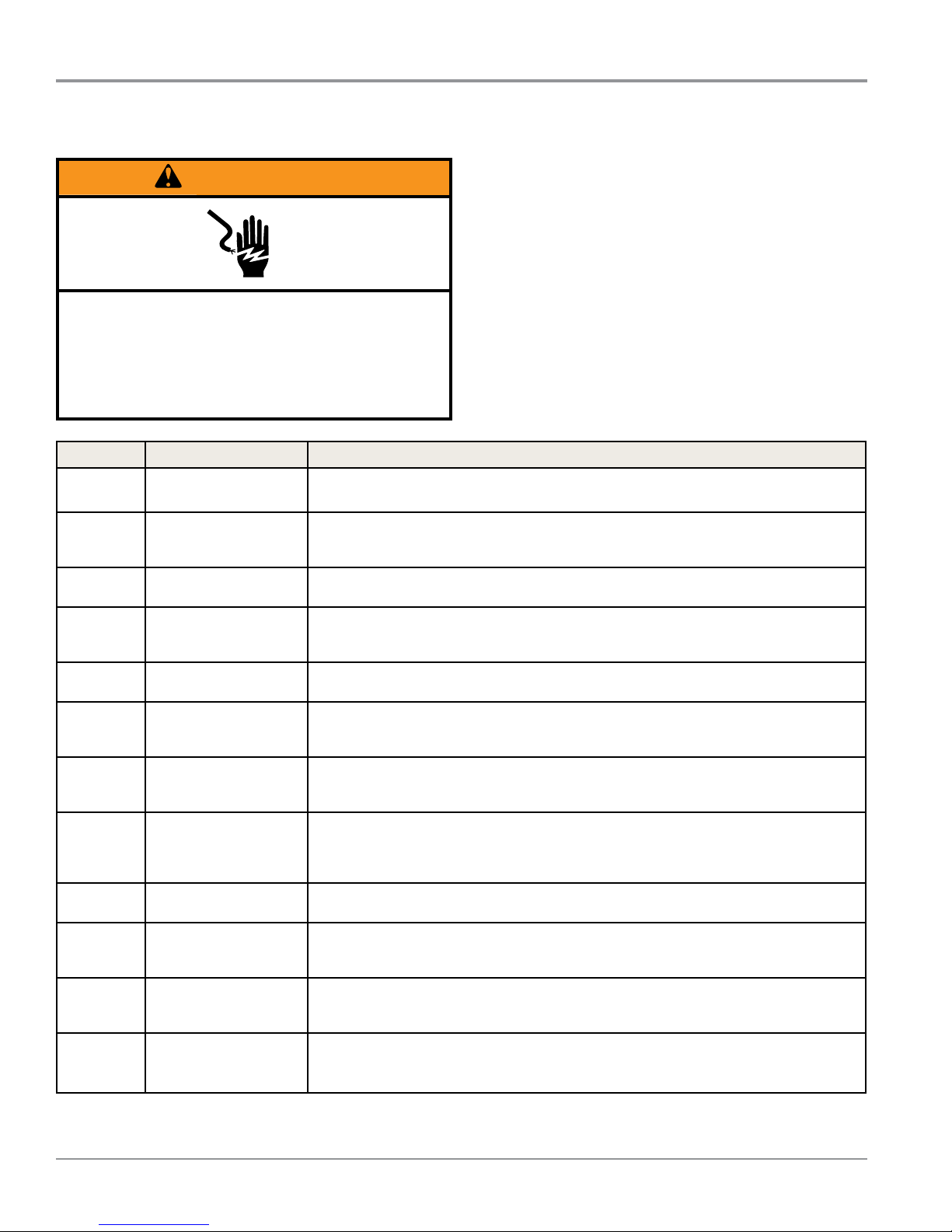
WARNING
Electrical Shock Hazard
Disconnect power before servicing.
Replace all parts and panels before operating.
Failure to do so can result in death or
electrical shock.
Code Description Explanation and Recommended Procedure
F1E1 Motor Relay Stuck On
Incorrect Controller
F1E3
F1E5
F2E1
F2E3
F2E4
F2E5
F3E1
F3E2
F3E3
F3E7
F4E1
Installed (on electric
models only)
Parameter Memory
Invalid
User Interface (UI)
Stuck Buon
User Interface (UI)
Mismatch
UI Soware Error:
Incompable
Parameter File
UI Soware Error:
Parameter Memory
Invalid
Exhaust Thermistor
Open/Shorted
Moisture Sensor Open/
Shorted
Inlet Thermistor Open/
Shorted
Rear Moisture Sensor
Open/Shorted (Maytag
Models Only)
Heater 1 Failure or
Connector Problem
Indicates an ACU problem.
• Replace the ACU.
Verify that the part numbers of the ACU and the User Interface are correct for the
dryer model displaying the fault/error code. Replace the ACU and/or UI that does not
match.
ACU parameter le missing: replace the ACU.
Indicates a stuck buon (depressed for over 20 seconds). This fault code will ONLY
appear when in the service diagnosc mode. See TEST #6: Buons and Indicators,
page 3-19.
Indicates a UI and ACU model ID parameter mismatch caused by replacement of
either the UI or ACU with an incorrect part number.
Replace the User Interface.
Replace the User Interface.
Indicates that the exhaust thermistor is open or shorted. If the temperature drops
below 18° F (> 50k ohms), the exhaust thermistor is open. If the temperature is
above 250° F (< 500 ohms), the exhaust thermistor has shorted. May occur if the J14
connector is not plugged into the ACU. See TEST #4a: Thermistors, page 3-14.
Indicates the moisture sensor strip is open or shorted. This fault code will only appear
when in the service diagnosc mode. See TEST #5: Moisture Sensor, page 3-17.
Indicates that the inlet thermistor is open or shorted. If the temperature drops below
18° F (> 245k ohms), the inlet thermistor is open. If the temperature is above 391° F (<
328 ohms), the inlet thermistor has shorted. See TEST #4a: Thermistors, page 3-14.
Indicates the rear moisture sensor strip is open or shorted. This fault code will only
appear when in the service diagnosc mode. See TEST #5: Moisture Sensor, page 3-17.
Indicates no voltage detected at the heater relay.
• Unplug dryer or disconnect power and check that the wires are plugged into the
heater element(s) and the relay(s) on the ACU.
2-8
Whirlpool & Maytag 9.2 Cu. Ft. Steam Dryer
n
Connued on next page...
DIAGNOSTICS & TROUBLESHOOTING
For Service Technician Use Only
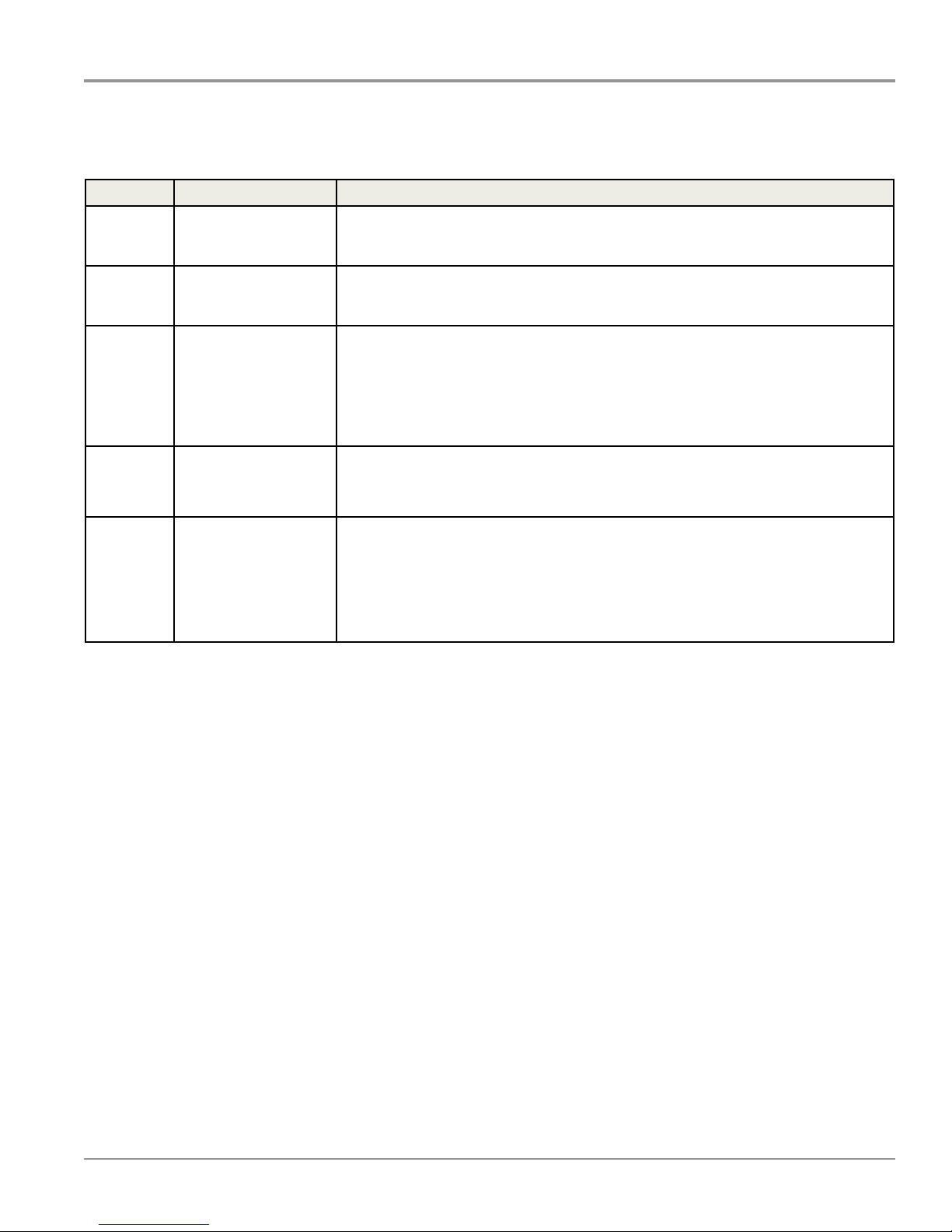
Service Fault/Error Codes
Connued from page 2-8
Code Description Explanation and Recommended Procedure
Heater 2 Failure or
F4E2
F4E3 Restricted Airow
F4E4
F4E5 High Limit
F6E2
F6E3
Connector Problem (on
electric models only)
L2 Line Voltage Error
(on electric models
only)
Communicaons Error
UI Cannot Hear ACU
Communicaon Error
ACU Cannot Hear UI
Indicates no voltage detected at the heater relay.
• Unplug dryer or disconnect power and check that the wires are plugged into the
heater element(s) and the relay(s) on the ACU.
Indicates low airow that may aect dryer performance.
• Conrm that airow system is not blocked; check lint screen, exhaust duct, and
exhaust fan.
Indicates low L2 voltage (less than 50 V) is detected at the CCU.
• Check to see if a household fuse has blown or a circuit breaker has tripped.
• Conrm the power cord is properly installed and plugged into the power outlet.
• Unplug dryer or disconnect power and check the relay connecons on the ACU.
• Gas Models Only: Unplug dryer or disconnect power and check the J14 connecon
on the ACU (harness loopback on pins 4 & 5).
Indicates that the temperature threshold of the dryer has been exceeded. This
excessive temperature is usually an indicator of poor airow and is most likely caused
by an exhaust restricon or failure of a component that drives airow such as the
blower wheel.
Communicaon between the ACU and UI has not been detected.
• Unplug dryer or disconnect power.
• Check the harness connuity and connecons between the ACU and UI.
• Check AC and DC supplies. See TEST #1: ACU Power Check, page 3-6.
• Replace the User Interface.
• Replace the ACU.
Whirlpool & Maytag 9.2 Cu. Ft. Steam Dryer
n
2-9
DIAGNOSTICS & TROUBLESHOOTING
For Service Technician Use Only
Troubleshoong Guide
NOTE: Always check for error codes rst (page 2-8 and 2-9)
Problem Possible Cause Checks & Tests
Won’t Power Up
• No operaon
• No keypad
response
• No LEDs or display
Will Not Start Cycle
(No response when
START buon is
pressed.)
Will Not Shut O
When Expected
Console Won’t Accept
Selecons
Drum Will Not Spin Drive Belt problem. See Test #3: Motor Circuit, page 3-10.
Will Not Heat Check Installaon. Verify proper dryer installaon.
No power to dryer. Check power at outlet, check circuit breaker, fuses, or juncon
box connecons.
Control Lock feature is enabled. Press and hold STEAM REFRESH for 3 seconds.
Connecon problem between AC
plug and dryer.
Connecon problem between ACU
and UI.
Power supplies not present at
machine electronics.
User Interface problem. See Test #6: Buons & Indicators, page 3-19.
Door not fully closed or striking the
door latch.
Control Lock feature is enabled. Press and hold STEAM REFRESH for 3 seconds.
Door Switch problem. See Test #7: Door Switch, page 3-20.
Drive Belt problem. See Test #3: Motor Circuit, page 3-10.
Thermal Fuse / Motor Problem See Test #3: Motor Circuit, page 3-10.
User Interface problem. See Test #6: Buons & Indicators, page 3-19.
ACU problem. See Test #1: ACU Power Check, page 3-6.
Poor airow. Check lint screen and exhaust vent. Clean if necessary.
Check the Power/Cancel or Start/
Pause buon.
Moisture Sensor problem. See Test #5: Moisture Sensor, page 3-17.
Thermistor problem. See Test #4a: Thermistors, page 3-14.
User Interface problem. See Test #6: Buons & Indicators, page 3-19.
ACU problem. See Test #1: ACU Power Check, page 3-6.
User selected invalid opon. Refer customer to “Use and Care Guide”.
Control Lock feature is enabled. Press and hold STEAM REFRESH for 3 seconds.
User Interface problem. See Test #6: Buons & Indicators, page 3-19.
Thermal Fuse. See Test #4b: Thermal Fuse, page 3-15.
Door switch problem. See Test #7: Door Switch, page 3-20.
Motor problem. See Test #3: Motor Circuit, page 3-10.
ACU problem. See Test #1: ACU Power Check, page 3-6.
Check for L1 and L2. Perform ACU L1 and L2 tests under Service Test Mode.
Heater system malfuncon or open
heater coil.
ACU problem. See Test #1: ACU Power Check, page 3-6.
See Test #2: Supply Connecons, page 3-8.
Check connecons and harness connuity between ACU and UI.
See Test #1: ACU Power Check, page 3-6.
Be sure the door is completely closed, then press and hold the
START buon.
Perform Key Acvaon & Encoder Test.
See Test #4: Heat System, page 3-12
2-10
Whirlpool & Maytag 9.2 Cu. Ft. Steam Dryer
n
Connued on next page...
 Loading...