

Whirlpool MET 9050 PAS INSTRUCTION FOR USE
MET 9050 PAS
INSTALLATION DATA SHEET
/*
The minimum distance between the support surface of the recipients on the cooking device and the lowest part
of the hood must not be less than 50 cm in case of electric cookers and 75 cm for gas or combination cookers. If
the installation instructions for the gas cooker specify a greater distance, this must be taken into account. It is
advisable to contact a qualified technician for installation.
Do not connect the hood to the electrical power supply until installation is completed.
Very heavy product; hood handling and installation must be carried out by at least two persons.
5019 918 01002
GB
MET 9050 PAS
17a
2 x
2,9x6,5
G
=
1
X
=
16
4 x 4x8
H
17a
17b
11
11
G
12
17b
F
4-13
18
15
B
6
5
8
6
5
9
4 x 3,5x9,5
4-13
8
3
2
5019 918 01002
14
10
7
9
1
0
1
4
GB
7

MET 9050 PAS
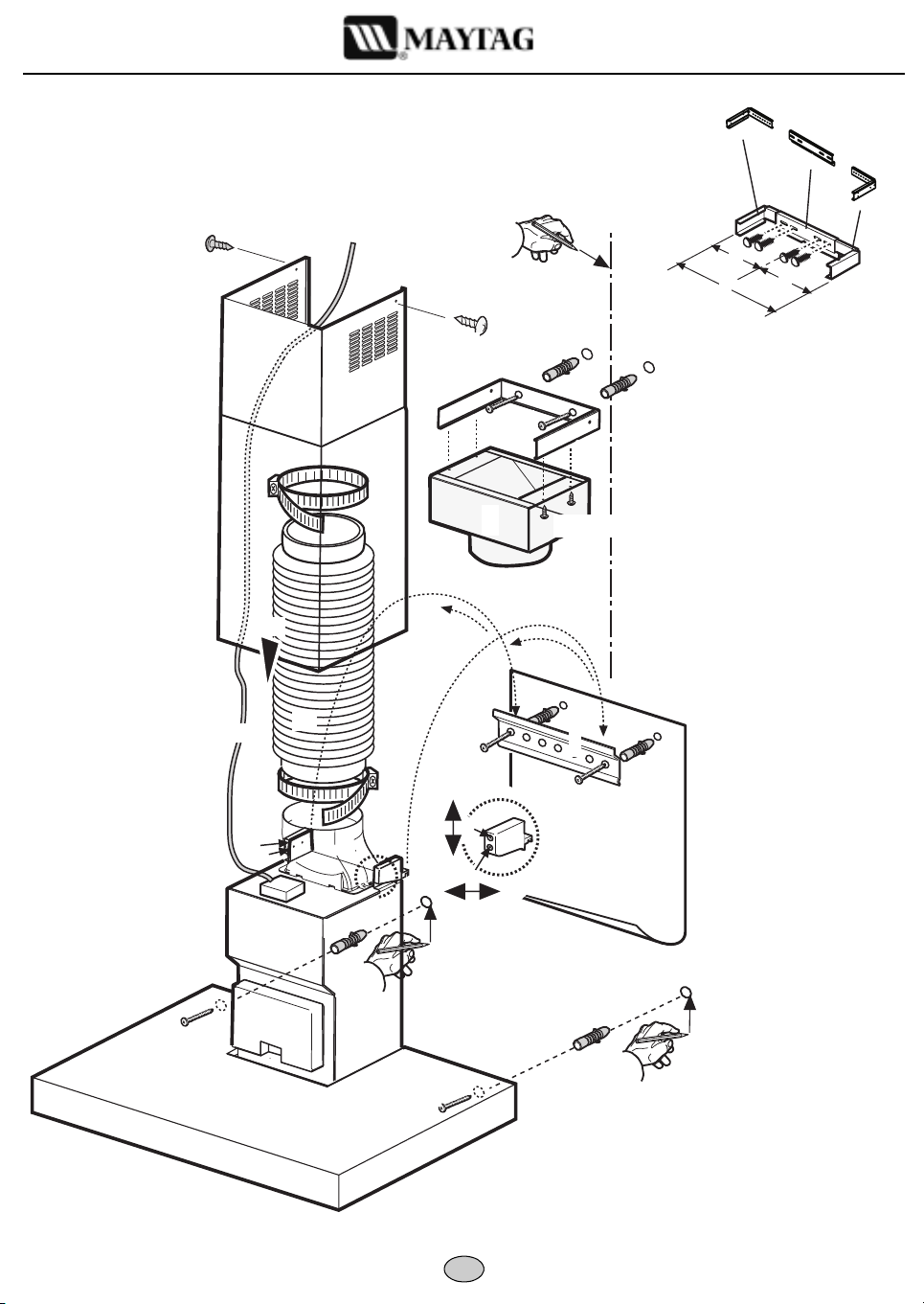
INSTALLATION - ASSEMBLY INSTRUCTIONS
Preliminary information for installing the hood:
Before beginning installation, decide which version of the hood you wish to use:
Extractor Version:
B
at the top of the hood.
Warning!
Filter Version:
Warning!
Disconnect the power supply at the domestic main switch before carrying out electrical connections.
Remove the grease filters.
Pre-assemble the three parts of the flue support bracket with 4 screws. The width X of the bracket G must be identical to the
internal width of the telescopic flue.
1.
2.
3.
4.
5.
6.
7.
8.
9.
10.
11.
12.
13.
14.
15.
16.
17.
18.
Refit the grease filter/s and check for correct hood operation.
If the hood has a carbon filter fitted, the filter must be removed.
If the hood does not have a carbon filter, order one and fit it before use.
Using a pencil, draw the centre line on the wall up to the ceiling to facilitate installation operations.
Apply the drilling template to the wall. Align the vertical centre-line on the drilling template with the centre-line drawn on
the wall. The template's bottom edge represents the bottom edge of the hood; remember that with installation completed
the bottom of the hood must be at least 50 cm above the cooktop in case of electric cookers and 75 cm in case of gas or
mixed cookers.
Place the support bracket on the hole diagram so that it matches the dotted rectangle, mark the two external holes and drill,
remove the hole diagram, insert 2 wall plugs and fix the hood support bracket with two 5x45 mm screws.
Hook the hood to the bracket.
Adjust the distance between the hood and the wall.
Adjust the hood horizontally.
From the inside of the extraction unit, mark the holes for fixing the hood.
Remove the hood from the bracket.
Drill on the mark (Ø 8 mm - see step 10).
Insert 2 wall plugs.
Fit the flue support bracket G to the wall and against the ceiling, use the support bracket as hole diagram (the small slot on
the support must match the line drawn on the wall - step 4) and mark 2 holes with the pencil, drill the holes (Ø 8 mm), and
finally insert 2 plugs.
Fix the flue support bracket to the wall with two 5x45 mm screws.
Hang the hood on the bottom mounting bracket.
Fix the hood to the wall with two 5x45 mm screws (ABSOLUTELY NECESSARY).
Connect an exhaust pipe (pipe and clamps are not supplied and must be bought separately) to the collar B located above
the extraction motor unit.
For extractor operation, connect the other end of the exhaust pipe to the home discharge device. For filter operation, fix
the deflector F to the flue support bracket G and connect the other end of the exhaust pipe to the deflector collar F. Once
the steam and fumes have been filtered by the carbon filter (not provided, to be ordered separately) they are conveyed back
to the kitchen through grid H.
Make all necessary electrical connections.
Fit the flue covers and fix them at the top with the two screws (
Slide the bottom section of the flue all the way over the extraction unit until it engages the seat above the hood.
fumes are extracted and expelled to the outside through an exhaust duct fixed to the collar
Air is filtered through a carbon filter and recycled into the surrounding environment.
20a
) to the flue bracket G (
20b
).
5019 918 01002
GB
 Loading...