

Whirlpool MDE22PDBYW0, MDG22PDBXW0, MDE22PRBYW0, MDE22PDBZW0, MDG22PDBWW0 Installation Instructions Manual
...
INSTALLATIONINSTRUCTIONS
COMMERCIALDRYER- Gas or Electric
INSTRUCTIONSPOUR L'INSTALLATIOND'UNE
SECHEUSECOMMERCIALE- A gaz ou (_lectrique
TABLEOF CONTENTS
DRYER SAFETY ............................................................................ 2
INSTALLATION REQUIREMENTS .............................................. 4
Tools and Parts .......................................................................... 4
Location Requirements .............................................................. 4
Electrical Requirements ............................................................ 6
Gas Supply Requirements ........................................................ 9
Venting Requirements ............................................................ 10
INSTALLATION INSTRUCTIONS - COIN SLIDE
AND COIN BOX ...................................................................... 11
INSTALLATION INSTRUCTIONS - GAS DRYER .................. 12
Make Gas Connection .............................................................. 12
Connect Vent ............................................................................ 12
Complete Installation .............................................................. 12
INSTALLATION INSTRUCTIONS- ELECTRIC DRYER ........ 13
Make Electrical Connection ...................................................... 13
Connect Vent ............................................................................ 20
Complete Installation .............................................................. 20
REVERSING THE DOOR SWING ............................................ 21
ELECTRONIC CONTROL SETUP .......................................... 22
MAINTENANCE INSTRUCTIONS ............................................ 22
WARRANTY ............................................................................ 23
TABLEDES MATIERES
SECURITte DE LA SECHEUSE .............................................. 24
EXIGENCES D'INSTALLATION ................................................ 26
Outillage et pi_ces .................................................................... 26
Exigences d'emplacement ...................................................... 26
Specifications electriques ....................................................... 28
Specifications de t'alimentation en gaz .................................. 30
Exigences concemant I'evacuation .......................................... 31
INSTRUCTIONS D'INSTALLATION - GLISSI#RE ET
CAISSE ._ MONNAIE ................................................................ 33
INSTRUCTIONS D'INSTALLATION - SECHEUSE A GAZ ...... 33
Raccordement h la canalisation de gaz .................................. 33
Raccordement du conduit d'evacuation ................................ 33
Achever I'instaltation ................................................................ 34
iNSTRUCTiONS D'INSTALLATION - SECHEUSE ELECTRIQUE....35
Raccordement du conduit d'evacuation ................................ 35
Achever I'installation ................................................................ 35
INVERSION DU SENS D'OUVERTURE DE LA PORTE ............ 36
REGLAGE DE LA COMMANDE ELECTRONIQUE ................ 38
INSTRUCTIONS D'ENTRETIEN .................................................. 38
GARANTIE ................................................................................ 39
W10184516A
www.whirlpool.com W10184517A-SP
DRYERSAFETY
Your safety and the safety of others are very important.
We have provided many important safety messages in this manual and on your appliance. Always read and obey all safety
messages.
This is the safety alert symbol.
This symbol alerts you to potential hazards that can kill or hurt you and others.
All safety messages will follow the safety alert symbol and either the word "DANGER" or "WARNING."
These words mean:
You can be killed or seriously injured if you don't immediately
follow instructions.
You can be killed or seriously injured if you don't follow
instructions.
All safety messages will tell you what the potential hazard is, tell you how to reduce the chance of injury, and tell you what can
happen if the instructions are not followed.
WARNING - "Risk of Fire"
- Clothes dryer installation must be performed by a qualified installer.
- install the clothes dryer according to the manufacturer's instructions and local codes,
- Do not install a clothes dryer with flexible plastic venting materials. {f flexible metal
(foil type} duct is installed, it must be of a specific type identified by the appliance
manufacturer as suitable for use with clothes dryers. Flexible venting materials are
known to collapse, be easily crushed, and trap lint. These conditions will obstruct
clothes dryer airflow and increase the risk of fire.
- To reduce the risk of severe injury or death, follow all installation instructions.
- Save these instructions.
m It is recommended that the owner post, in a prominent location, instructions for the customer's use in the event the customer smells
gas. This information should be obtained from your gas supplier.
m Post the following warning in a prominent location.
I FOR YOUR SAFETYDo not store or use gasoline or other flammable vapors and liquids in the vicinity of this or any other appliance. I
WARNING: For your safety, the information in this manual must be followed to minimize
the risk of fire or explosion, or to prevent property damage, personal injury, or death.
- Do not store or use gasoline or other flammable vapors and liquids in the vicinity of this
or any other appliance.
- WHAT TO DO iF YOU SMELL GAS:
®Do not try to light any appliance.
• Do not touch any electrical switch; do not use any phone in your building.
= Clear the room, building, or area of all occupants.
= Immediately call your gas supplier from a neighbor's phone. Follow the gas supplier's
instructions.
= if you cannot reach your gas supplier, call the fire department.
- Installation and service must be performed by a qualified installer, service agency, or
the gas supplier.
WARNING: Gas leaks cannot always be detected by smell.
Gas suppliers recommend that you use a gas detector approved by UL or CSA.
For more information, contact your gas supplier.
If a gas leak is detected, follow the "What to do if you smell gas" instructions.
In the State of Massachusetts, the following installation instructions apply:
[] Installations and repairs must be performed by a qualified or licensed contractor, plumber, or gasfitter qualified or licensed by
the State of Massachusetts.
[] if using a ball valve, it shall be a T-handle type.
[] A flexible gas connector, when used, must not exceed 3 feet.
IMPORTANT: The gas installation must conform with local codes, or in the absence of local codes, with the National Fuel Gas
Code, ANSI Z223.1/NFPA 54 or the Canadian Natural Gas and Propane Installation Code, CSA B149.1.
The dryer must be electrically grounded in accordance with local codes, or in the absence of local codes, with the National
Electrical Code, ANSI/NFPA 70 or Canadian Electrical Code, CSA C22.1.
3
iMPORTANT SAFETY iNSTRUCTiONS
WARNING: To reduce the risk of fire, electric shock, or injury to personswhen using the dryer, follow basic precautions,
including the following:
[] Read all instructions before using the dryer.
[] Do not place items exposed to cooking oils in your dryer.
Items contaminated with cooking oils may contribute to
a chemical reaction that could cause a load to catch fire.
[] Do not dry articles that have been previously cleaned in,
washed in, soaked in, or spotted with gasoline, dry=
cleaning solvents, or other flammable or explosive
substances as they give off vapors that could ignite or
explode.
[] Do not allow children to play on or in the dryer. Close
supervision of children is necessary when the dryer is
used near children.
[] Before the dryer is removed from service or discarded,
remove the door to the drying compartment.
[] Do not reach into the dryer if the drum is moving.
[] Do not install or store the dryer where it will be exposed
to the weather.
[] Do not tamper with controls.
SAVE THESE INSTRUCTIONS
[] Do not repair or replace any part of the dryer or attempt
any servicing unless specifically recommended in this
Use and Care Guide or in published user-repair
instructions that you understand and have the skills to
carry out.
[] Do not use fabric softeners or products to eliminate static
unless recommended by the manufacturer of the fabric
softener or product.
[] Do not use heat to dry articles containing foam rubber or
similarly textured rubber-like materials.
[] Clean lint screen before or after each load.
[] Keep area around the exhaust opening and adjacent
surrounding areas free from the accumulation of lint, dust,
and dirt.
[] The interior of the dryer and exhaust vent should be
cleaned periodically by qualified service personnel.
[] See installation instructions for grounding requirements.
INSTALLATIONREQUIREMENTS
Gather the required tools and parts before starting installation.
Read and follow the instructions provided with any tools
listed here.
Tools needed
[] 8" or 10" Pipe wrench [] Level
[] 8" or 10" adjustable [] 1/4"socket and wrench
wrench [] Vent clamps
[] Flat-blade screwdriver [] Pipe-joint compound
[] Phillips screwdriver resistant to LP gas
[] Adjustable wrench that [] Caulk gun and caulk (for
opens to 1" (2.5 cm) or 1" installing new exhaust
(25 mm) hex-head socket vent)
wrench [] Pliers
[] Security T-20 TORX_'t [] Stiff bladed putty knife
driver
Parts supplied
Remove parts bag from dryer drum. Check that all parts were
included.
[] Foot boot (4)
[] Dryer foot (4)
[] Service door lock cam
Explosion Hazard
Keep flammable materials and vapors, such as
gasoline, away from dryer.
Do not install in a garage.
Failure to do so can result in death, explosion, or fire.
If installing a gas dryer:
IMPORTANT: Observe all governing codes and ordinances.
[] Check code requirements: Some codes limit or do not permit
installation of clothes dryers in garages, closets, or sleeping
quarters. Contact your local building inspector.
[] Make sure that lower edges of the cabinet, plus the back and
bottom sides of the dryer, are free of obstructions to permit
adequate clearance of air openings for combustion air. See
"Recessed Area and Closet Installation Instructions" below
for minimum spacing requirements.
NOTE: The dryer must not be installed in an area where it will
be exposed to water and/or weather.
1 ® TORX is a registered trademark of Acument Intellectual Properties, LLC.
4
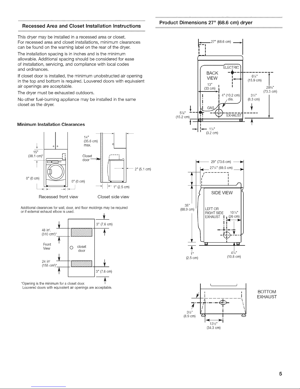
Recessed Area and Closet Installation instructions
Product Dimensions 27" (68.6 cm} dryer
This dryer may be installed in a recessed area or closet.
For recessed area and closet installations, minimum clearances
can be found on the warning label on the rear of the dryer.
The installation spacing is in inches and is the minimum
allowable. Additional spacing should be considered for ease
of installation, servicing, and compliance with local codes
and ordinances.
If closet door is installed, the minimum unobstructed air opening
in the top and bottom is required. Louvered doors with equivalent
air openings are acceptable.
The dryer must be exhausted outdoors.
No other fuel-burning appliance may be installed in the same
closet as the dryer.
Minimum Installation Clearances
(35.6 cm)
max. _ l
Closet _ H / .... 1
15"
(38.1 cm)*
t
o o
_iiiiii-L.
r-mEz3---
I
I
T............
0" (Ocm)
H........ II........
Recessed front view Closet side view
Additional clearances for wall, door, and floor moldings may be required
or if external exhaust elbow is used.
48 inL
(310 cm2)*
Front
View O
24in_ -_-
(155 cm2)__j___
0" (Ocm)
closet
door
i
I_ 1" (2.5 cm)
3" (7.6 cm)
_!_
3" (7.6cm)
57/8,, _===
(15.2 cm)__
T'
T"
35"
(88.9 cm)
(2.5 cm)
_.-=--27" (68.8 cm)
=m|
I
I
=_|
"_ ELECTRIC
BACK =_= =
VIEW I
13" I I
I I 4" (10.2 cm)
i 1 dis,
t
I
_ 11A"
(3.2 cm)
27_A'' (89.5 cm)
/
I
I
LEFTOR
RIGHTSIDE 10W'
EXHAUST I I (26 cm)
1 "
29" (73.6 cm)
SIDE VlEW
|
I
I
I f
I
41/4''
(10.8 cm)
(15.9 cm)
61A" l
31/4" I
.....
283/4 ''
(73.3 cm)
*Opening is the minimum for a closet door.
Louvered doors with equivalent air openings are acceptable.
i i
I/I T
31/2"I/I !
(8.9 cm) _'_ I
I"
(34.3 cm)
BOTTOM
EXHAUST
5
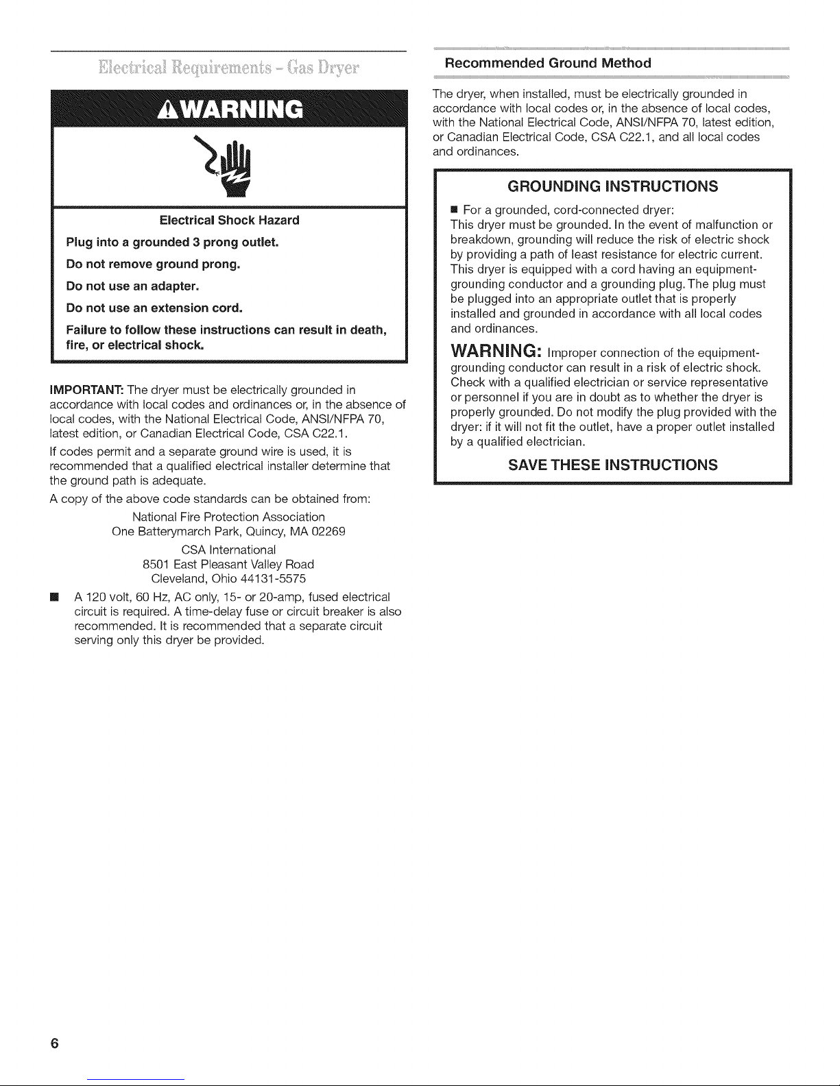
Recommended Ground Method
The dryer, when installed, must be electrically grounded in
accordance with local codes or, in the absence of local codes,
with the National Electrical Code, ANSl/NFPA 70, latest edition,
or Canadian Electrical Code, CSA C22.1, and all local codes
and ordinances.
_SHHHHHHHHHHHHHHHHHHHHHHHHHHHHHHHHHHHHHHHHHHHHHHH_
GROUNDING INSTRUCTIONS
Electrical Shock Hazard
Plug into a grounded 3 prong outlet.
Do not remove ground prong.
Do not use an adapter.
Do not use an extension cord.
Failure to follow these instructions can result in death,
fire, or electrical shock.
IMPORTANT: The dryer must be electrically grounded in
accordance with local codes and ordinances or, in the absence of
local codes, with the National Electrical Code, ANSl/NFPA 70,
latest edition, or Canadian Electrical Code, CSA C22.1.
If codes permit and a separate ground wire is used, it is
recommended that a qualified electrical installer determine that
the ground path is adequate.
A copy of the above code standards can be obtained from:
National Fire Protection Association
One Batterymarch Park, Quincy, MA 02269
CSA international
8501 East Pleasant Valley Road
Cleveland, Ohio 44131-5575
[] A 120 volt, 60 Hz, AC only, 15- or 20-amp, fused electrical
circuit is required. A time-delay fuse or circuit breaker is also
recommended. It is recommended that a separate circuit
serving only this dryer be provided.
[] For a grounded, cord-connected dryer:
This dryer must be grounded. In the event of malfunction or
breakdown, grounding will reduce the risk of electric shock
by providing a path of least resistance for electric current.
This dryer is equipped with a cord having an equipment-
grounding conductor and a grounding plug.The plug must
be plugged into an appropriate outlet that is properly
installed and grounded in accordance with all local codes
and ordinances.
WARNING" improper connection of the equipment-
grounding conductor can result in a risk of electric shock.
Check with a qualified electrician or service representative
or personnel if you are in doubt as to whether the dryer is
properly grounded. Do not modify the plug provided with the
dryer: if it will not fit the outlet, have a proper outlet installed
by a qualified electrician.
SAVE THESE INSTRUCTIONS
if using a power supply cord:
it is your responsibility
[] To contact a qualified electrical installer.
[] To be sure that the electrical connection is adequate and in
conformance with the National Electrical Code, ANSl/NFPA
70-latest edition and all local codes and ordinances.
The National Electrical Code requires a 4-wire power supply
connection for homes built after 1996, dryer circuits involved
in remodeling after 1996, and all mobile home installations.
A copy of the above code standards can be obtained from:
National Fire Protection Association, One Batterymarch Park,
Quincy, MA 02269.
[] To supply the required 3 or 4 wire, single phase, 120/240 volt,
60 Hz., AC only electrical supply (or 3 or 4 wire, 120/208 volt
electrical supply, if specified on the serial/rating plate) on a
separate 30-amp circuit, fused on both sides of the line. A
time-delay fuse or circuit breaker is recommended. Connect
to an individual branch circuit. Do not have a fuse in the
neutral or grounding circuit.
[] Do not use an extension cord.
[] If codes permit and a separate ground wire is used, it is
recommended that a qualified electrician determine that the
ground path is adequate.
Electrical Connection
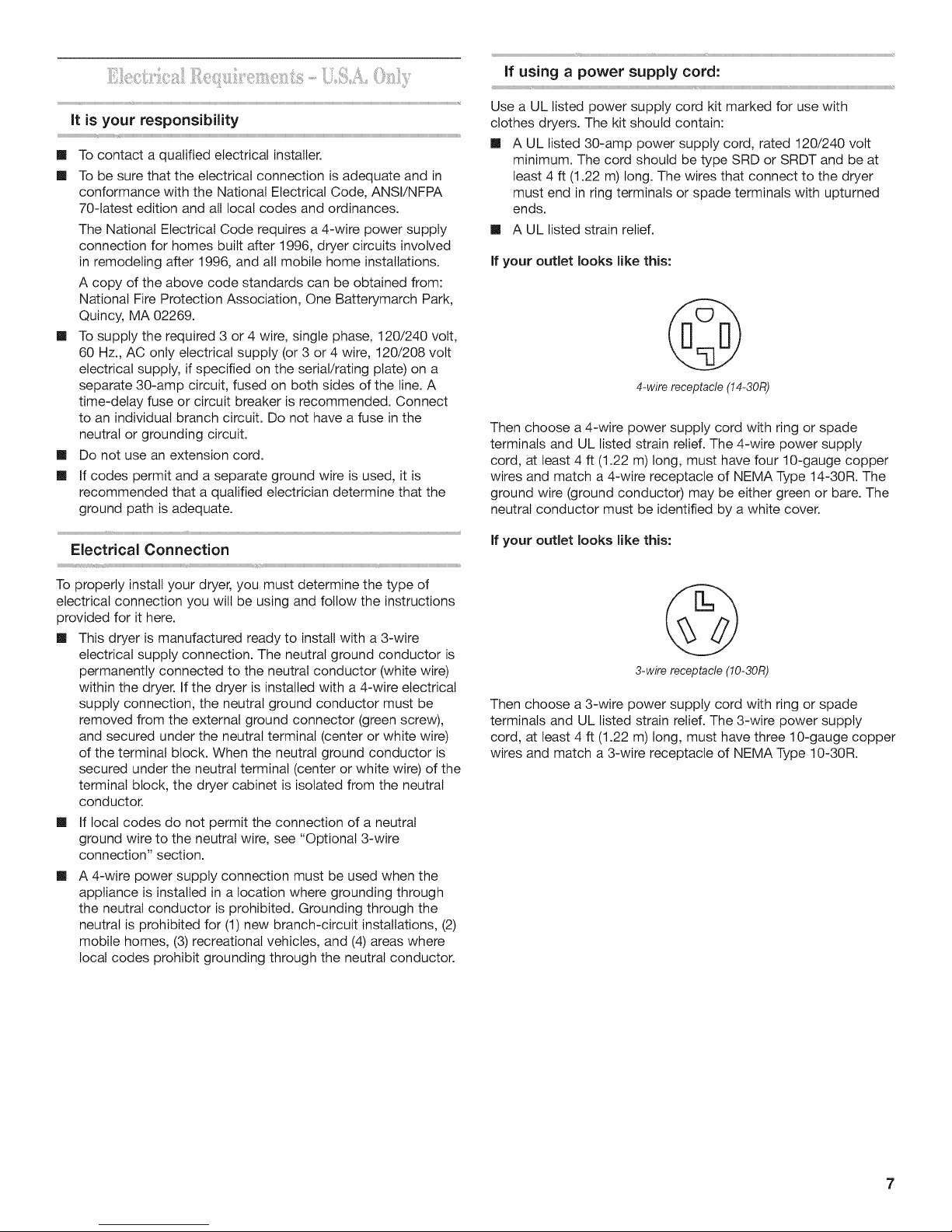
Use a UL listed power supply cord kit marked for use with
clothes dryers. The kit should contain:
[] A UL listed 30-amp power supply cord, rated 120/240 volt
minimum. The cord should be type SRD or SRDT and be at
least 4 ft (1.22 m) long. The wires that connect to the dryer
must end in ring terminals or spade terminals with upturned
ends.
[] A UL listed strain relief.
If your ouUet looks like this:
4-wirereceptacle(14-30R)
Then choose a 4-wire power supply cord with ring or spade
terminals and UL listed strain relief. The 4-wire power supply
cord, at least 4 ft (1.22 m) long, must have four 10-gauge copper
wires and match a 4-wire receptacle of NEMA Type 14-30R. The
ground wire (ground conductor) may be either green or bare. The
neutral conductor must be identified by a white cover.
If your ouUet looks like this:
To properly install your dryer, you must determine the type of
electrical connection you will be using and follow the instructions
provided for it here.
[] This dryer is manufactured ready to install with a 3-wire
electrical supply connection. The neutral ground conductor is
permanently connected to the neutral conductor (white wire)
within the dryer. If the dryer is installed with a 4-wire electrical
supply connection, the neutral ground conductor must be
removed from the external ground connector (green screw),
and secured under the neutral terminal (center or white wire)
of the terminal block. When the neutral ground conductor is
secured under the neutral terminal (center or white wire) of the
terminal block, the dryer cabinet is isolated from the neutral
conductor.
[] If local codes do not permit the connection of a neutral
ground wire to the neutral wire, see "Optional 3-wire
connection" section.
[] A 4-wire power supply connection must be used when the
appliance is installed in a location where grounding through
the neutral conductor is prohibited. Grounding through the
neutral is prohibited for (1) new branch-circuit installations, (2)
mobile homes, (3) recreational vehicles, and (4) areas where
local codes prohibit grounding through the neutral conductor.
3-wire receptacle (10-30R)
Then choose a 3-wire power supply cord with ring or spade
terminals and UL listed strain relief. The 3-wire power supply
cord, at least 4 ft (1.22 m) long, must have three 10-gauge copper
wires and match a 3-wire receptacle of NEMA Type 10-30R.
7
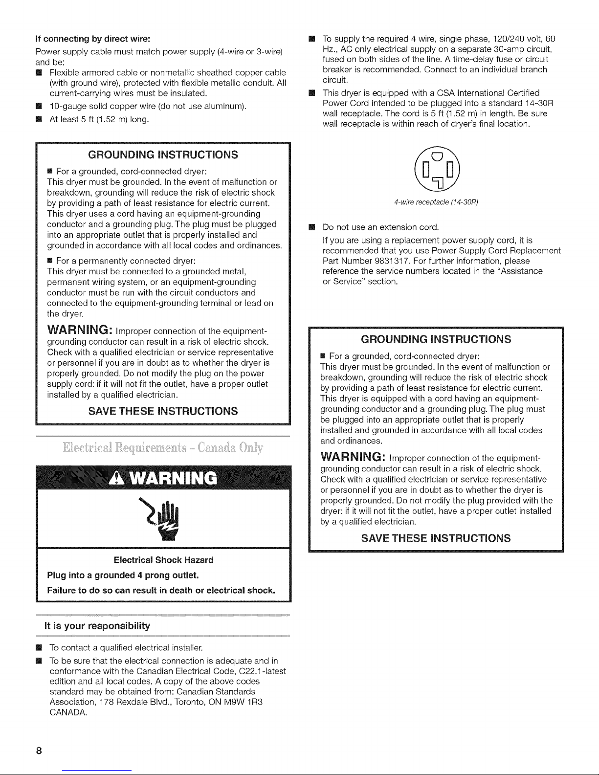
If connecting by direct wire:
Power supply cable must match power supply (4-wire or 3-wire)
and be:
[] Flexible armored cable or nonmetallic sheathed copper cable
(with ground wire), protected with flexible metallic conduit. All
current-carrying wires must be insulated.
[] 10-gauge solid copper wire (do not use aluminum).
[] At least 5 ft (1.52 m) long.
GROUNDING INSTRUCTIONS
m For a grounded, cord-connected dryer:
This dryer must be grounded. In the event of malfunction or
breakdown, grounding will reduce the risk of electric shock
by providing a path of least resistance for electric current.
This dryer uses a cord having an equipment-grounding
conductor and a grounding plug. The plug must be plugged
into an appropriate outlet that is properly installed and
grounded in accordance with all local codes and ordinances.
m For a permanently connected dryer:
This dryer must be connected to a grounded metal,
permanent wiring system, or an equipment-grounding
conductor must be run with the circuit conductors and
connected to the equipment-grounding terminal or lead on
the dryer.
WARNING: improper connection of the equipment-
grounding conductor can result in a risk of electric shock.
Check with a qualified electrician or service representative
or personnel if you are in doubt as to whether the dryer is
properly grounded. Do not modify the plug on the power
supply cord: if it will not fit the outlet, have a proper outlet
installed by a qualified electrician.
SAVE THESE INSTRUCTIONS
[] To supply the required 4 wire, single phase, 120/240 volt, 60
Hz., AC only electrical supply on a separate 30-amp circuit,
fused on both sides of the line. A time-delay fuse or circuit
breaker is recommended. Connect to an individual branch
circuit.
[] This dryer is equipped with a CSA international Certified
Power Cord intended to be plugged into a standard 14-30R
walt receptacle. The cord is 5 ft (1.52 m) in length. Be sure
watt receptacle is within reach of dryer's final location.
4-wirereceptacle(14-30R)
[]
Do not use an extension cord.
If you are using a replacement power supply cord, it is
recommended that you use Power Supply Cord Replacement
Part Number 9831317. For further information, please
reference the service numbers located in the "Assistance
or Service" section.
GROUNDING INSTRUCTIONS
[] For a grounded, cord-connected dryer:
This dryer must be grounded. In the event of malfunction or
breakdown, grounding will reduce the risk of electric shock
by providing a path of least resistance for electric current.
This dryer is equipped with a cord having an equipment-
grounding conductor and a grounding plug. The plug must
be plugged into an appropriate outlet that is properly
installed and grounded in accordance with all local codes
and ordinances.
Electrical Shock Hazard
Plug into a grounded 4 prong outlet,
Failure to do so can result in death or electrical shock.
It is your responsibility
[]
To contact a qualified electrical installer.
[]
To be sure that the electrical connection is adequate and in
conformance with the Canadian Electrical Code, C22.1-1atest
edition and all local codes. A copy of the above codes
standard may be obtained from: Canadian Standards
Association, 178 Rexdate Blvd., Toronto, ON M9W 1R3
CANADA.
WARNING: improper connection of the equipment-
grounding conductor can result in a risk of electric shock.
Check with a qualified electrician or service representative
or personnel if you are in doubt as to whether the dryer is
properly grounded. Do not modify the plug provided with the
dryer: if it will not fit the outlet, have a proper outlet installed
by a qualified electrician.
SAVE THESE INSTRUCTIONS
_iiiiiiii_i!:_!!iil;iiii_i:!ii?ili:i::iiiii?¸!i:!_%i?_!/ii:ii::'_!i!:_:_iiii_:_i_i_!!%:i:!!ii_
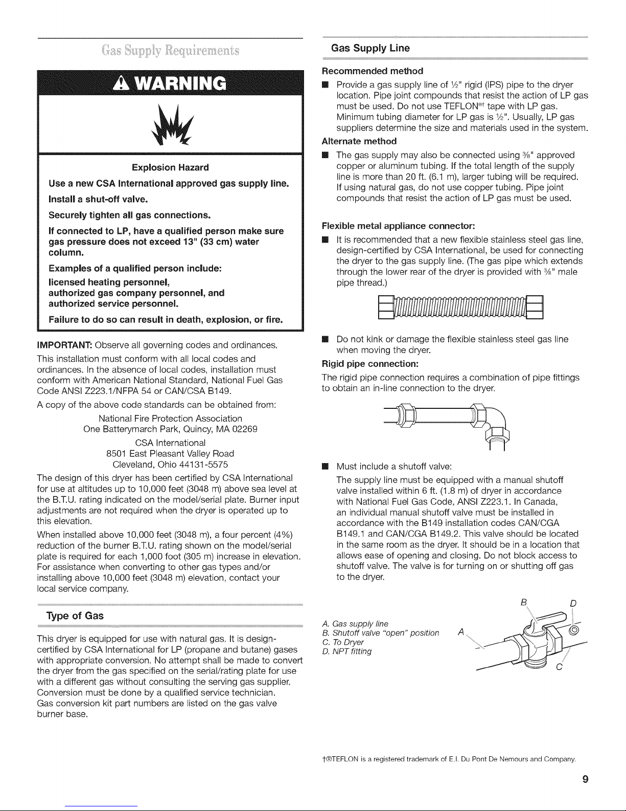
Explosion Hazard
Use a new CSA International approved gas supply line.
Install a shut=off valve.
Securely tighten all gas connections.
if connected to LP, have a qualified person make sure
gas pressure does not exceed 13" (33 cm) water
column.
Examples of a qualified person include:
licensed heating personnel,
authorized gas company personnel, and
authorized service personnel.
Failure to do so can result in death, explosion, or fire.
Gas Supply Line
Recommended method
[] Provide a gas supply line of 1/2"rigid (IPS) pipe to the dryer
location. Pipe joint compounds that resist the action of LP gas
must be used. Do not use TEFLON_'ttape with LP gas.
Minimum tubing diameter for LP gas is 1/2".Usually, LP gas
suppliers determine the size and materials used in the system.
Alternate method
[] The gas supply may also be connected using %" approved
copper or aluminum tubing. If the total length of the supply
line is more than 20 ft. (6.1 m), larger tubing will be required.
If using natural gas, do not use copper tubing. Pipe joint
compounds that resist the action of LP gas must be used.
Flexible metal appliance connector:
[] It is recommended that a new flexible stainless steel gas line,
design-certified by CSA International, be used for connecting
the dryer to the gas supply line. (The gas pipe which extends
through the lower rear of the dryer is provided with %" mate
pipe thread.)
IMPORTANT: Observe all governing codes and ordinances.
This installation must conform with all local codes and
ordinances. In the absence of local codes, installation must
conform with American National Standard, National Fuel Gas
Code ANSI Z223.1/NFPA 54 or CAN/CSA B149.
A copy of the above code standards can be obtained from:
National Fire Protection Association
One Batterymarch Park, Quincy, MA 02269
CSA International
8501 East Pleasant Valley Road
Cleveland, Ohio 44131-5575
The design of this dryer has been certified by CSA International
for use at altitudes up to 10,000 feet (3048 m) above sea level at
the B.T.U. rating indicated on the model/serial plate. Burner input
adjustments are not required when the dryer is operated up to
this elevation.
When installed above 10,000 feet (3048 m), a four percent (4%)
reduction of the burner B.T.U. rating shown on the model/serial
plate is required for each 1,000 foot (305 m) increase in elevation.
For assistance when converting to other gas types and/or
installing above 10,000 feet (3048 m) elevation, contact your
local service company.
Type of Gas
This dryer is equipped for use with natural gas. It is design-
certified by CSA International for LP (propane and butane) gases
with appropriate conversion. No attempt shall be made to convert
the dryer from the gas specified on the serial/rating plate for use
with a different gas without consulting the serving gas supplier.
Conversion must be done by a qualified service technician.
Gas conversion kit part numbers are listed on the gas valve
burner base.
[] Do not kink or damage the flexible stainless steel gas line
when moving the dryer.
Rigid pipe connection:
The rigid pipe connection requires a combination of pipe fittings
to obtain an in-line connection to the dryer.
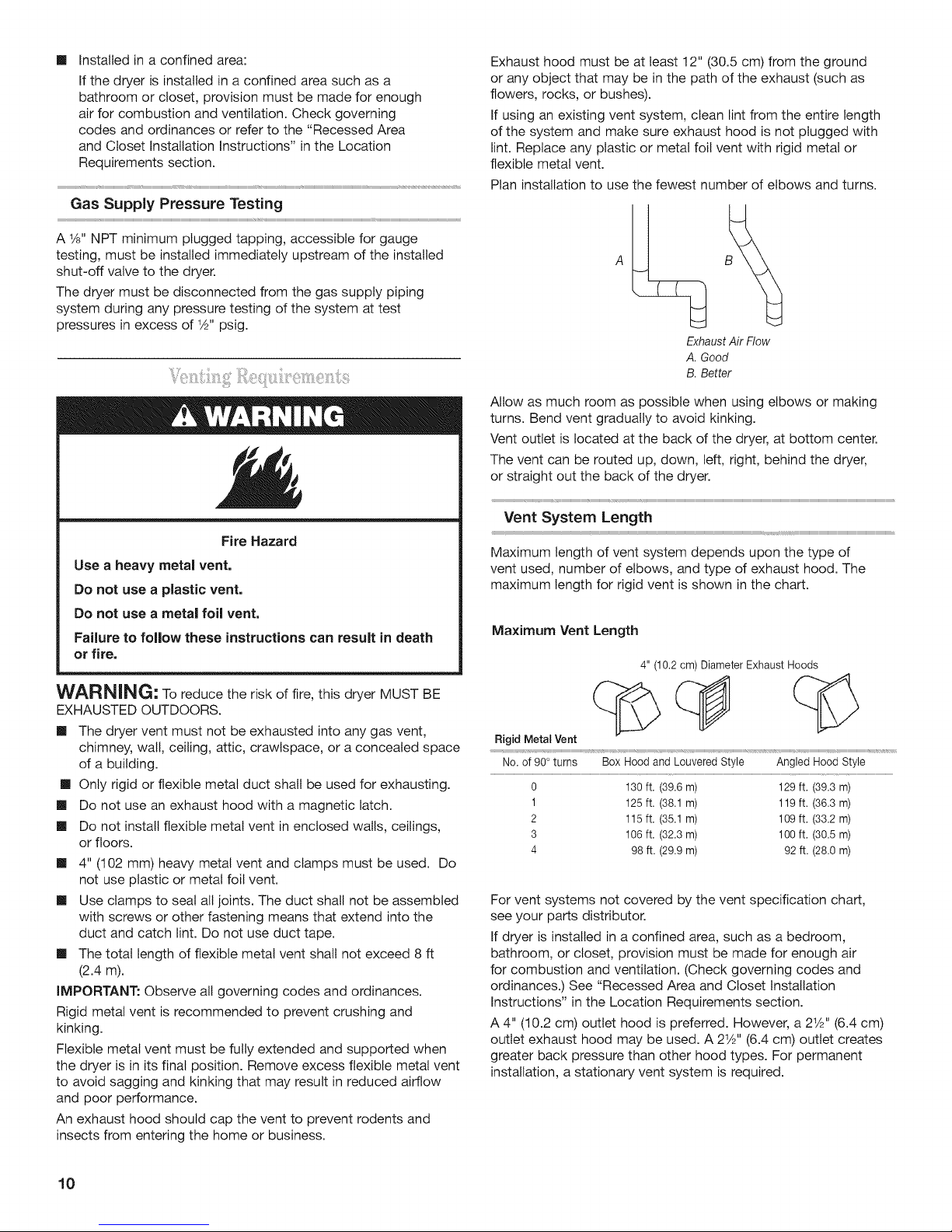
[] Must include a shutoff valve:
The supply line must be equipped with a manual shutoff
valve installed within 6 ft. (1.8 m) of dryer in accordance
with National Fuel Gas Code, ANSI Z223.1. In Canada,
an individual manual shutoff valve must be installed in
accordance with the B149 installation codes CAN/CGA
B149.1 and CAN/CGA B149.2. This valve should be located
in the same room as the dryer. It should be in a location that
allows ease of opening and closing. Do not block access to
shutoff valve. The valve is for turning on or shutting off gas
to the dryer.
B D
\
A. Gas supply line
B. Shutoff valve "open" position
C. To Dryer
D. NPT fitting
1-®TEFLON is a registered trademark of E.I. Du Pont De Nemours and Company.
9
[] Installed in a confined area:
Ifthe dryer is installed in a confined area such as a
bathroom or closet, provision must be made for enough
air for combustion and ventilation. Check governing
codes and ordinances or refer to the "Recessed Area
and Closet Installation Instructions" in the Location
Requirements section.
Gas Supply Pressure Testing
A 1/8"NPT minimum plugged tapping, accessible for gauge
testing, must be installed immediately upstream of the installed
shut-off valve to the dryer.
The dryer must be disconnected from the gas supply piping
system during any pressure testing of the system at test
pressures in excess of 1Z2"psig.
Exhaust hood must be at least 12" (30.5 cm) from the ground
or any object that may be in the path of the exhaust (such as
flowers, rocks, or bushes).
If using an existing vent system, clean lint from the entire length
of the system and make sure exhaust hood is not plugged with
lint. Replace any plastic or metal foil vent with rigid metal or
flexible metal vent.
Plan installation to use the fewest number of elbows and turns.
ExhaustAir Flow
A.Good
B.Better
Allow as much room as possible when using elbows or making
turns. Bend vent gradually to avoid kinking.
Vent outlet is located at the back of the dryer, at bottom center.
The vent can be routed up, down, left, right, behind the dryer,
or straight out the back of the dryer.
Fire Hazard
Use a heavy metal vent,
Do not use a plastic vent.
Do not use a metal foil vent,
Failure to follow these instructions can result in death
or fire.
WARNING; To reduce the risk of fire, this dryer MUST BE
EXHAUSTED OUTDOORS.
[] The dryer vent must not be exhausted into any gas vent,
chimney, wall, ceiling, attic, crawtspace, or a concealed space
of a building.
[] Only rigid or flexible metal duct shall be used for exhausting.
[] Do not use an exhaust hood with a magnetic latch.
[] Do not install flexible metal vent in enclosed walls, ceilings,
or floors.
[] 4" (102 mm) heavy metal vent and clamps must be used. Do
not use plastic or metal foil vent.
[] Use clamps to seat all joints. The duct shall not be assembled
with screws or other fastening means that extend into the
duct and catch lint. Do not use duct tape.
[] The total length of flexible metal vent shall not exceed 8 ft
(2.4 m).
iMPORTANT: Observe all governing codes and ordinances.
Rigid metal vent is recommended to prevent crushing and
kinking.
Flexible metal vent must be fully extended and supported when
the dryer is in its final position. Remove excess flexible metal vent
to avoid sagging and kinking that may result in reduced airflow
and poor performance.
An exhaust hood should cap the vent to prevent rodents and
insects from entering the home or business.
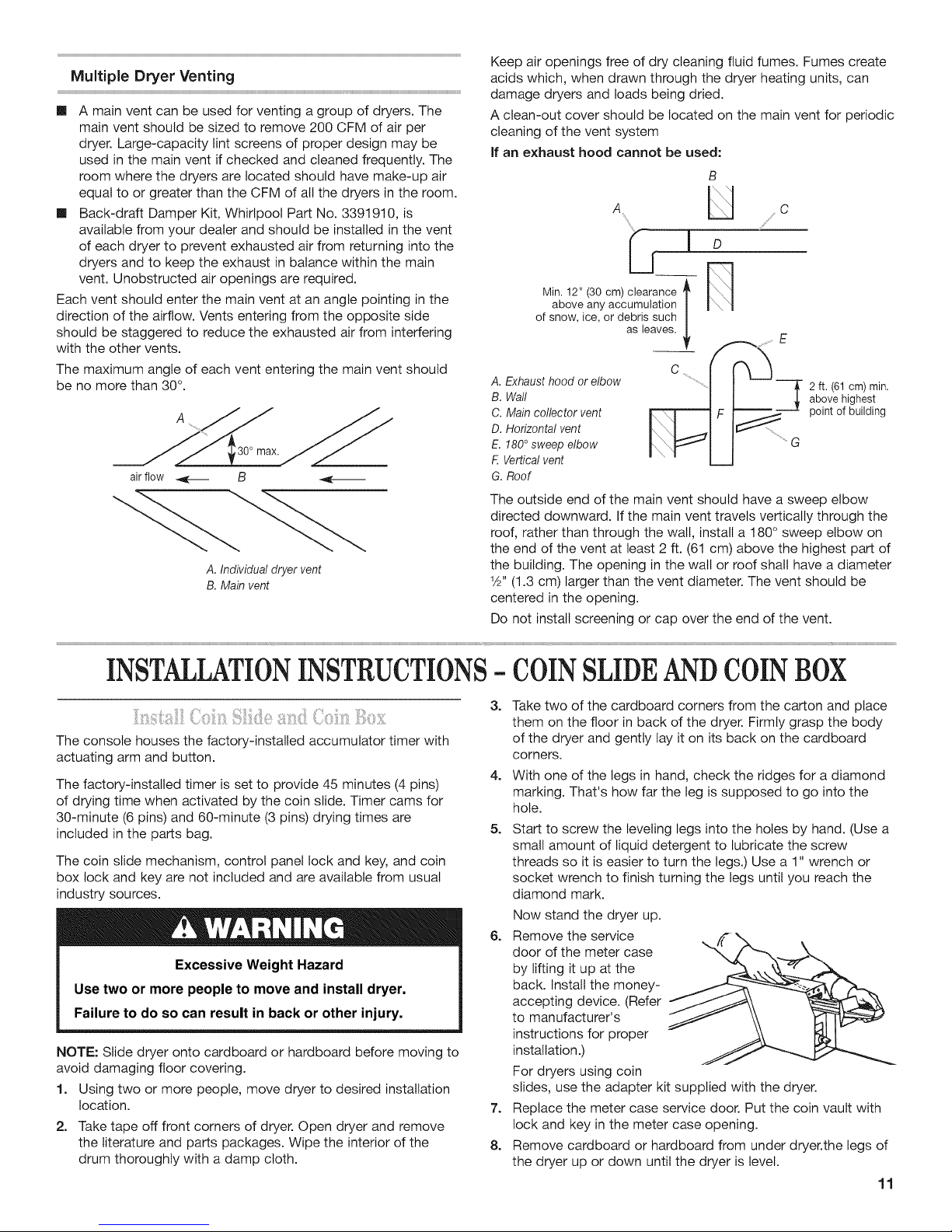
Maximum length of vent system depends upon the type of
vent used, number of elbows, and type of exhaust hood. The
maximum length for rigid vent is shown in the chart.
Maximum Vent Length
4" (10.2 cm) Diameter Exhaust Hoods
Rigid Metal Vent
; ;i ; r ; r r ; ; r ri r; r r ; r; r r
No.of90°turns BoxHoodandLouveredStyle AngledHoodStyle
0 130 ft, (39,8 m) 129 ft, (39,3 m)
1 125 ft, (38,1 m) 119 ft, (36,3 m)
2 115 ft, (35,1 m) 109 ft, (33,2 m)
3 106 ft, (32,3 m) 100 ft, (30,5 m)
4 98 ft. (29.9 m) 92 ft. (28.0 m)
For vent systems not covered by the vent specification chart,
see your parts distributor.
If dryer is installed in a confined area, such as a bedroom,
bathroom, or closet, provision must be made for enough air
for combustion and ventilation. (Check governing codes and
ordinances.) See "Recessed Area and Closet Installation
Instructions" in the Location Requirements section.
A 4" (10.2 cm) outlet hood is preferred. However, a 21/," (6.4 cm)
outlet exhaust hood may be used. A 21/2`' (6.4 cm) outlet creates
greater back pressure than other hood types. For permanent
installation, a stationary vent system is required.
10
[] A main vent can be used for venting a group of dryers. The
main vent should be sized to remove 200 CFM of air per
dryer. Large-capacity lint screens of proper design may be
used in the main vent if checked and cleaned frequently. The
room where the dryers are located should have make-up air
equal to or greater than the CFM of all the dryers in the room.
[] Back-draft Damper Kit, Whirlpool Part No. 3391910, is
available from your dealer and should be installed in the vent
of each dryer to prevent exhausted air from returning into the
dryers and to keep the exhaust in balance within the main
vent. Unobstructed air openings are required.
Each vent should enter the main vent at an angle pointing in the
direction of the airflow. Vents entering from the opposite side
should be staggered to reduce the exhausted air from interfering
with the other vents.
The maximum angle of each vent entering the main vent should
be no more than 30°.
A
Keep air openings free of dry cleaning fluid fumes. Fumes create
acids which, when drawn through the dryer heating units, can
damage dryers and loads being dried.
A clean-out cover should be located on the main vent for periodic
cleaning of the vent system
If an exhaust hood cannot be used:
B
A U °
O_ _ ................E
2 ft. (61 cm) min.
above highest
point of building
air flow _ B _---
A.Individualdryervent
B. Mainvent
INSTALLATIONINSTRUCTIONS- COINSLIDEANDCOINBOX
The console houses the factory-installed accumulator timer with
actuating arm and button.
The factory-installed timer is set to provide 45 minutes (4 pins)
of drying time when activated by the coin slide. Timer cams for
30-minute (6 pins) and 60-minute (3 pins) drying times are
included in the parts bag.
The coin slide mechanism, control panel lock and key, and coin
box lock and key are not included and are available from usual
industry sources.
Excessive Weight Hazard
Use two or more people to move and install dryer.
Failure to do so can result in back or other injury.
NOTE: Slide dryer onto cardboard or hardboard before moving to
avoid damaging floor covering.
1. Using two or more people, move dryer to desired installation
location.
2. Take tape off front corners of dryer. Open dryer and remove
the literature and parts packages. Wipe the interior of the
drum thoroughly with a damp cloth.
G.Roof
The outside end of the main vent should have a sweep elbow
directed downward. If the main vent travels vertically through the
roof, rather than through the walt, install a 180° sweep elbow on
the end of the vent at least 2 ft. (61 cm) above the highest part of
the building. The opening in the wall or roof shall have a diameter
1Z2"(1.3 cm) larger than the vent diameter. The vent should be
centered in the opening.
Do not install screening or cap over the end of the vent.
3=
Take two of the cardboard corners from the carton and place
them on the floor in back of the dryer. Firmly grasp the body
of the dryer and gently lay it on its back on the cardboard
corners.
4=
With one of the legs in hand, check the ridges for a diamond
marking. That's how far the leg is supposed to go into the
hole.
5=
Start to screw the leveling legs into the holes by hand. (Use a
small amount of liquid detergent to lubricate the screw
threads so it is easier to turn the legs.) Use a 1" wrench or
socket wrench to finish turning the legs until you reach the
diamond mark.
Now stand the dryer up.
6=
Remove the service
door of the meter case
by lifting it up at the
back. Install the money-
accepting device. (Refer
to manufacturer's
instructions for proper
installation.)
For dryers using coin
slides, use the adapter kit supplied with the dryer.
7=
Replace the meter case service door. Put the coin vault with
lock and key in the meter case opening.
8.
Remove cardboard or hardboard from under dryer.the legs of
the dryer up or down until the dryer is level.
11
INSTALLATIONINSTRUCTIONS- GASDRYER
Excessive Weight Hazard
Use two or more people to move and install dryer.
Failure to do so can result in back or other injury.
1. Remove red cap from gas pipe on back of dryer.
2. Connect gas supply to dryer. Use a pipe thread compound
approved for the type of gas supplied. If flexible metal tubing
is used, be certain there are no kinks.
If necessary for service, open the front lower service panel by
using a V4" nutdriver to remove the 2 hex-head screws from
the bottom of the panel. Then lift up on the panel while pulling
the bottom of the panel away from the dryer.
3. Open the shutoff valve in the gas supply line and make sure
the unit has its own gas supply opened.
4. Test all connections by brushing on an approved noncorrosive
leak-detection solution. Bubbles will show a leak. Correct any
leak found.
1=
With dryer in final position, place level on top of the dryer, first
side to side; then front to back. }fthe dryer is not level, adjust
the legs of the dryer up or down until the dryer is level.
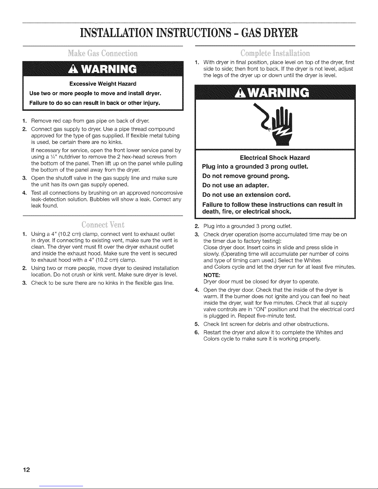
Electrical Shock Hazard
Plug into a grounded 3 prong outlet.
Do not remove ground prong.
Do not use an adapter.
Do not use an extension cord.
Fai{ure to follow these instructions can result in
death, fire, or electrical shock.
1. Using a 4" (10.2 cm) clamp, connect vent to exhaust outlet
in dryer. If connecting to existing vent, make sure the vent is
clean. The dryer vent must fit over the dryer exhaust outlet
and inside the exhaust hood. Make sure the vent is secured
to exhaust hood with a 4" (10.2 cm) clamp.
2. Using two or more people, move dryer to desired installation
location. Do not crush or kink vent. Make sure dryer is level.
3. Check to be sure there are no kinks in the flexible gas line.
2. Plug into a grounded 3 prong outlet.
3. Check dryer operation (some accumulated time may be on
the timer due to factory testing):
Close dryer door. Insert coins in slide and press slide in
slowly. (Operating time will accumulate per number of coins
and type of timing cam used.) Select the Whites
and Colors cycle and let the dryer run for at least five minutes.
NOTE:
Dryer door must be closed for dryer to operate.
4. Open the dryer door. Check that the inside of the dryer is
warm. If the burner does not ignite and you can feel no heat
inside the dryer, wait for five minutes. Check that all supply
valve controls are in "ON" position and that the electrical cord
is plugged in. Repeat five-minute test.
5. Check lint screen for debris and other obstructions.
6. Restart the dryer and allow it to complete the Whites and
Colors cycle to make sure it is working properly.
12

INSTALLATIONINSTRUCTIONS-ELECTRICDRYER
Power Supply Cord
Fire Hazard
Use a new UL listed 30 amp power supply cord.
Use a UL listed strain relief.
Disconnect power before making electrical connections.
Connect neutral wire (white or center wire) to center
terminal (silver).
Ground wire (green or bare wire) must be connected to
green ground connector.
Connect remaining 2 supply wires to remaining
2 terminals (gold).
Securely tighten all electrical connections.
Failure to do so can result in death, fire, or
electrical shock.
2. Remove the hold-down screw and terminal block cover.
3. Install strain relief.
A. Neutral ground wire
B. External ground
conductor screw
C. Center, silver-colored
terminal block screw
D. Terminalblock cover
and holddown screw
1. Disconnect power.
Electrical Connection Options
If your location has: And you will be Go to Section
connecting to:
4-wire receptacle
(NEMA Type 14-30R)
(_ A UL listed, 120/240-
30-amp, dryer power
volt minimum,
4-wire connection:
Power supply cord
supply cord*
3-wire receptacle
(NEMA type 10-30R)
volt minimum,
A UL listed, 120/240-
30-amp, dryer power
3-wire connection:
Power supply cord
supply cord*
4-wire direct _._t[[[_,[_,(,_ A fused disconnect or 4-wire connection:
circuit breaker box* Direct Wire
(12.7 cm)
3-wire direct _ A fused disconnect or 3-wire connection:
circuit breaker box* Direct Wire
.... ..................................................... ;; r; ; ;; ; ................................................................................
(8.9cm)
*If local codes do not permit the connection of a cabinet-ground conductor to the neutral wire, go to "Optional 3-wire connection"
section.
13

Power supply cord strain relief:
[]
Remove the screws from a 3/4"(1.9 cm)
UL listed strain relief (UL marking on strain
relief). Put the tabs of the two clamp
sections into the hole below the terminal
block opening so that one tab is pointing
up and the other is pointing down, and
hold in place.
Tighten strain relief screws enough to hold the
two clamp sections together.
A. Strain relief tab
pointing up
B. Hole below terminal
block opening
C. Clamp section
D. Strain relief tab
pointing down
[]
Put power supply cord through the strain
relief. Be sure that the wire insulation on
the power supply cord is inside the strain
relief. The strain relief should have a tight
fit with the dryer cabinet and be in a
horizontal position. Do not further tighten
strain relief screws at this point.
5.
Now complete installation following
instructions for your type of electrical
connection:
4-wire (recommended)
3-wire (if 4-wire is not available)
14

Power supply cord,
4=wire connection:
IMPORTANT: A 4-wire connection is
required for mobile homes and where local
codes do not permit the use of 3-wire
connections.
B
J
j_
S
J
c
E _
3.
Connect ground wire (green or bare) of
power supply cord to external ground
conductor screw. Tighten screw.
F ...................._ ............................................................... E
::; g
G
D
A. 4-wire receptacle (NEMA type 14-30R)
B. 4-prong plug
C. Ground prong
D. Neutral prong
E.Spade terminals with upturned ends
F. 3A" (1.9 cm) UL listed strain relief
G. Ring terminals
1.
Remove center silver-colored terminal
block screw.
2.
Remove neutral ground wire from
external ground conductor screw.
Connect neutral ground wire and the
neutral wire (white or center wire) of
power supply cord under center,
silver-colored terminal block screw.
Tighten screw.
g J_¸
A. External ground conductor screw
B. Ground wire (green or bare) of power supply cord
C. 3/4"(1.9 cm) UL listed strain relief
D. Center silver-colored terminal block screw
E. Neutral ground wire
E Neutral wire (white or center wire)
4.
Connect the other wires to
outer terminal block screws.
!!
Tighten screws.
5. Tighten strain relief screws.
c
6. Insert tab of terminal block cover into
slot of dryer rear panel. Secure cover
with holddown screw.
7. You have completed your electrical
connection. Now go to "Venting
Requirements."
A. Externalground conductor screw - Dotted line shows position of
NEUTRALground wire before being moved to center silvercolored
terminal block screw.
B. Center silver-colored terminal block screw
C. Neutral ground wire
D. Neutral wire (white or center wire)
E. 3A" (1.9 cm) UL listed strain relief
E
15

Power supply cord,
3-wire connection:
B D
A
A. 3-wire receptacle (NEMAtype 10-30R)
B. 3-wire plug
C. Neutral prong
D. Spade terminals with upturned ends
E. 3/4"(1.9 cm) UL listed strain relief
F. Ring terminals
G. Neutral (white or center wire)
E
Y
G F
Use where local codes permit connecting
cabinet=ground conductor to neutral wire.
1. Loosen or remove center silver-colored
terminal block screw.
2. Connect neutral wire (white or center
wire) of power supply cord to the center,
silver-colored terminal screw of the
terminal block. Tighten screw.
3. Connect the other wires to outer terminal
block screws. Tighten screws.
I I F
A
4. Tighten strain relief screws.
5. Insert tab of terminal block cover into
slot of dryer rear panel. Secure cover
with holddown screw.
6. You have completed your electrical
connection. Now go to "Venting
Requirements."
A. External ground conductor screw
B.Neutral ground wire
C. Center silver-colored terminal
block screw
D. Neutral wire (white or center wire)
E.3/4_'(1.9 cm) UL listed strain relief
16

Direct Wire Method = U.S. Only
Direct wire cable must match power supply (4-wire or 3-wire)
and be:
[] Flexible armored cable or nonmetallic sheathed copper cable
(with ground wire), protected with flexible metallic conduit.
All current-carrying wires must be insulated.
[] 10-gauge solid copper wire (do not use aluminum).
[] At least 5 ft. (1.52 m) long.
1. Disconnect power.
2. Remove hold-down screw and terminal block cover.
Fire Hazard
Use 10 gauge copper wire.
Use a UL listed strain relief.
Disconnect power before making electrical connections.
Connect neutral wire (white or center wire) to center
terminal (silver).
Ground wire (green or bare wire) must be connected to
green ground connector.
Connect remaining 2 supply wires to remaining
2 terminals (gold).
Securely tighten all electrical connections.
Failure to do so can result in death, fire, or
electrical shock.
Direct wire strain relief:
[] Unscrew the removable conduit
connector and any screws from a
3/4"(1.9 cm) UL listed strain relief (UL
marking on strain relief). Put the threaded
section of the strain relief through the
hole below the terminal block opening.
Reaching inside the terminal block
opening, screw the removable conduit
connector onto the strain relief threads.
D A.Neutralgroundwire
B.Externalground
conductorscrew
C.Center,silver-colored
terminalblockscrew
D. Terminalblock cover
andholddownscrew
3= Install 3A"conduit connector into the hole below the terminal
block opening. Connect flexible metallic conduit and tighten
connector screw. Install direct wire cable through the flexible
metallic conduit.
[]
Put direct wire cable through the strain
relief. The strain relief should have a tight
fit with the dryer cabinet and be in a
horizontal position. Tighten strain relief
screw against the direct wire cable.
5=
Now complete installation following
instructions for your type of electrical
connection:
4-wire (recommended)
3-wire (if 4-wire is not available)
A. Removable conduit connector
B. Hole below terminal block opening
C. Strain relief threads
17

DirectWire,
4-wireconnection:
IMPORTANT: A 4-wire connection is required for mobile
homes and where local codes do not permit the use of
3-wire connections,
Direct wire cable must have 5 ft (1.52 m) of extra length so
dryer can be moved if needed.
Strip 5" (12.7 cm) of outer
covering from end of cable,
leaving bare ground wire at 5"
(12.7 cm). Cut 11Z2'' (3.8 cm)
from 3 remaining wires. Strip
insulation back 1" (2.5 cm).
Shape ends of wires into a
hook shape.
A
E
F
C
When connecting to the terminal block,
place the hooked end of the wire under the
screw of the terminal block (hook facing
right), squeeze hooked end together and
tighten screw, as shown.
1.
Remove center silver-colored terminal
block screw.
2.
Remove neutral ground wire from external ground
conductor screw. Connect neutral ground wire and
place the hooked end (hook facing right) of the neutral
wire (white or center wire) of direct wire cable under
the center screw of the terminal block. Squeeze
hooked ends together. Tighten screw.
3. Connect ground wire
(green or bare) of direct
wire cable to external
ground conductor screw.
Tighten screw.
4. Place the hooked ends of
the other direct wire cable
wires under the outer
terminal block screws
(hooks facing right). Squeeze hooked ends together.
Tighten screws.
5. Tighten strain relief screw.
6. Insert tab of terminal block cover into slot of dryer rear
panel. Secure cover with holddown screw.
7. You have completed your electrical connection.
Now go to "Venting Requirements."
A. External ground conductor screw
B. Ground wire (green or bare) of power supply cable
C. '3/4"(1.9 cm) UL listed strain relief
D. Center silver-colored terminal block screw
E. Neutral ground wire
E Neutral wire (white or center wire)
A. External ground conductor screw - Dotted line shows
position of NEUTRAL ground wire before being moved
to center silver-colored terminal block screw.
B. Center silver-colored terminal block screw
C. Neutral ground wire
D. Neutral wire (white or center wire)
E. 3/4"(1.9cm) UL listed strain relief
B
18

Direct wire,
3=wire connection:
Use where local codes permit connecting
cabinet-ground conductor to neutral wire.
Direct wire cable must have 5 ft (1.52 m) of extra length
so dryer can be moved if needed.
Strip 31_" (8.9 cm) of outer t?.,_ c_
covering from end of cable. Strip
insulation back 1" (2.5 cm). If
using 3-wire cable with ground
wire, cut bare wire even with outer
covering. Shape ends of wires into _s,_c_
a hook shape.
When connecting to the terminal block, place the
terminal block (hook facing right), squeeze hooked
end together, and tighten screw, as shown.
hooked end of the wire under the screw of the 1_1
1. Loosen or remove center silver-colored terminal
block screw.
2. Place the hooked end of the neutral wire (white //
or center wire) of direct wire cable under the
center screw of terminal block (hook facing
right). Squeeze hooked end together. Tighten screw.
3. Place the hooked ends of the other direct
wire cable wires under the outer terminal
block screws (hooks facing right). Squeeze
hooked ends together. Tighten screws.
4. Tighten strain relief screw.
5. Insert tab of terminal block cover into slot
of dryer rear panel. Secure cover with
holddown screw.
6. You have completed your electrical connection.
Now go to "Venting Requirements."
\\
!
A ri l C
..........................k_ ",i', ,; ...............................o
_/j:::: :::_J ..........................................................................................E
A. External ground conductor screw
B.Neutral ground wire
C.Center silver-colored terminal block screw
D.Neutral wire (white or center wire)
E.3/4"(1.9 cm) UL listed strain relief
!
......¢
Optional,
3-wire connection:
Use for direct wire or power supply cord
where local codes do not permit
connecting cabinet-ground conductor
to neutral wire.
1. Remove center silver-colored terminal
block screw.
2. Remove neutral ground wire from
external ground conductor screw.
Connect neutral ground wire and the
neutral wire (white or center wire) of
power supply cord/cable under center,
silver-colored terminal block screw.
Tighten screw.
3. Connect the other wires to outer terminal
block screws. Tighten screws.
4. Tighten strain relief screws.
5. Connect a separate copper ground wire
from the external ground conductor
screw to an adequate ground.
6. Insert tab of terminal block cover into
slot of dryer rear panel. Secure cover
with holddown screw.
B. Center silver-colored terminal block screw
C. Neutral ground wire
D. Neutral wire (white or center wire)
E. 3/4"(1.9 cm) UL listed strain relief
F. Grounding path determined by a qualified
electrician
19

1. Using a 4" (10.2 cm) clamp, connect vent to exhaust outlet
in dryer. If connecting to existing vent, make sure the vent is
clean. The dryer vent must fit over the dryer exhaust outlet
and inside the exhaust hood. Make sure the vent is secured
to exhaust hood with a 4" (10.2 cm) clamp.
2. Move dryer into final position. Do not crush or kink vent. Make
sure dryer is level.
1. With dryer in final position, place level on top of the dryer, first
side to side; then front to back. If the dryer is not level, adjust
the legs of the dryer up or down until the dryer is level.
2. Plug in dryer or reconnect power.
3. Check dryer operation (some accumulated time may be on
the timer due to factory testing):
Close dryer door. Insert coins in slide and press slide in
slowly. (Operating time will accumulate per number of coins
and type of timing cam used.) Select the Whites
and Colors cycle and let the dryer run for at least five minutes.
NOTE:
Dryer door must be closed for dryer to operate.
4. Open the dryer door. Check that the inside of the dryer is
warm. If the burner does not ignite and you can feel no heat
inside the dryer, wait for five minutes. Check that all supply
valve controls are in "ON" position and that the electrical cord
is plugged in. Repeat five-minute test.
5. Check lint screen for debris and other obstructions.
6. Restart the dryer and allow it to complete the Whites and
Colors cycle to make sure it is working properly.
2O

REVERSINGTHEDOORSWING
You can change your door swing from a right-side opening to
left-side opening, if desired.
Place a towel or soft cloth on top of the dryer or work space
to protect the surface.
1. Remove the 4 screws that hold the door hinge on the front
panel of the dryer.
A. Dryer front panel
B. Door assembly
1.
Use a small flat-blade screwdriver to remove 2 plug strips
from the inner door. Slide the head of the screwdriver under
the plugs, being certain not to scratch the inner door surface.
Lift up.
®
2. Remove the 4 screws that attach the door hinge and move
the hinge to the other side. Reinstall the 4 screws.
2.
Lay the door assembly on a flat, protected surface with the
inside (inner door assembly) facing up.
3.
Remove the 6 Phillips head screws to release the outer door
assembly from the inner door assembly, as indicated in the
illustration below. It is important that you remove only the 6
indicated screws.
4. Lift the inner door assembly off the outer door assembly.
5. Rotate outer door 180 °.
180 °
A. Door hinge
3. Reinstall plug strips on opposite side of the inner door.
4. Check for fingerprints on the inside of the glass.
Clean glass if necessary.
5. Place the inner door assembly inside the outer door assembly.
To fit correctly, the inner door assembly edge fits completely
inside the outer door assembly edge.
6. Reassemble the inner and outer door assemblies with the
6 screws.
21

1. Use a small flat-blade screwdriver to remove plug strip from
the dryer door opening. Slide the head of the screwdriver
under the strip, being sure not to scratch the dryer surface.
Lift up.
2. Remove the strike using a #2 Phillips screw driver.
3. Install strike on the opposite side.
1.
Reattach door to dryer front panel with the 4 screws.
f--..
@
A. Dryer front panel
B. Door assembly
A,
A. Plug strip (cannot be
seen from this angle)
B. Door catch
ELECTRONICCONTROL SETUP
See Tech Sheet for information on setup.
MAINTENANCE INSTRUCTIONS
Maintenance instructions:
mClean lint screen after each cycle.
mRemoving accumulated lint:
* From inside the dryer cabinet:
Lint should be removed every 2 years or more often,
depending on dryer usage. Cleaning should be done
by a qualified person.
From the exhaust vent:
Lint should be removed every 2 years, or more often,
depending on dryer usage.
mKeep area around dryer clear and free from combustible
materials, gasoline and other flammable vapors and liquids.
mKeep dryer area clear and free from items that would obstruct
the flow of combustion and ventilation air.
2. Check for fingerprints on the inside of the glass.
Clean glass if necessary.
3. Close door and check that it latches securely.
If dryer does not operate, check the following:
[] Electric supply is connected.
[] Circuit breaker is not tripped or house fuse is not blown.
[] Door is closed.
[] Controls are set in a running or "ON" position.
[] START button has been pushed firmly.
[] For gas dryers, check that gas supply shutoff valves are set
in open position.
If you need assistance:
The Commercial Laundry Support Center will answer any
questions about operating or maintaining your dryer not covered
in the Installation Instructions. The Commercial Laundry Support
Center is open 24 hours a day, 7 days a week. Just dial
1-800 NO BELTS (1-800-662-3587) -- the call is toll free.
When you call, you will need the dryer model number and serial
number. Both numbers can be found on the serial-rating plate
located in the dryer door well.
22

WHIRLPOOLCOMMERCIALLAUNDRYWARRANTY:
CAM2752,CEM2750,CGM2751,CAM2762,CEM2760,CGM2761,CSP2760,
CSP2761,CEW91OO,CGW91OO,CHW9900
LiMiTED WARRANTY
For the first three years from the date of purchase, when this commercial appliance is installed, maintained, and operated according to the
instructions attached to or furnished with the product, Whirlpool Corporation (thereafter "Whirlpool") will pay for factory specified parts or
original equipment manufacturer parts to correct defects in materials or workmanship that existed when this major appliance was purchased.
YOUR SOLE AND EXCLUSIVE REMEDY UNDER THIS LIMITED WARRANTY SHALL BE PRODUCT REPAIRAS PROVIDED HEREIN. Proof of
original purchase date is required to obtain service under this warranty.
iTEMS WHIRLPOOL WiLL NOT PAY FOR
This limited warranty does not cover:
1.
Costs including transportation, shipping, or custom duties for covered parts.
2.
Service calls to correct the installation of your commercial appliance, to instruct you how to use your commercial appliance,
to replace or repair fuses, or to correct external wiring or plumbing.
3.
Replacement parts or repair labor if this commercial appliance is used for other than normal, commercial use or when it is used
in a manner that is inconsistent to published user or operator instructions and/or installation instructions.
4.
Damage resulting from improper handling of product during delivery, theft, accident, alteration, misuse, abuse, fire, flood,
acts of God, improper installation, installation not in accordance with local electrical or plumbing codes, or use of products
not approved by Whirlpool.
5=
Pickup and Delivery. This commercial appliance is designed to be repaired on location.
6.
Repairs to parts or systems resulting from unauthorized modifications made to the commercial appliance.
7.
The removal and reinstallation of your commercial appliance if it is installed in an inaccessible location or is not installed
in accordance with published installation instructions.
8=
Damage resulting from exposure to chemicals.
9.
Changes to the building, room, or location needed in order to make the commercial appliance operate correctly.
DiSCLAiMER OF iMPLiED WARRANTIES
IMPLIED WARRANTIES, INCLUDING ANY IMPLIED WARRANTY OF MERCHANTABILITY OR IMPLIED WARRANTY OF FITNESS FOR A
PARTICULAR PURPOSE, ARE LIMITED TO THREE YEARS OR THE SHORTEST PERIOD ALLOWED BY LAW. Some states and provinces do
not allow limitations on the duration of implied warranties of merchantability or fitness, so this limitation may not apply to you. This warranty
gives you specific legal rights, and you also may have other rights that vary from state to state or province to province.
LiMiTATiON OF REMEDIES; EXCLUSION OF iNCiDENTAL AND CONSEQUENTIAL DAMAGES
YOUR SOLE AND EXCLUSIVE REMEDY UNDER THIS LIMITED WARRANTY SHALL BE PRODUCT REPAIR AS PROVIDED HEREIN.
WHIRLPOOL SHALL NOT BE LIABLE FOR iNCIDENTAL OR CONSEQUENTIAL DAMAGES. Some states and provinces do not allow
the exclusion or limitation of incidental or consequential damages, so these limitations and exclusions may not apply to you. This
warranty gives you specific legal rights, and you also may have other rights that vary from state to state or province to province.
Ifyou need service, please contact your authorized Whirlpool Commercial Laundry distributor. To locate your authorized Whirlpool
Commercial Laundry distributor, or for web inquiries, visit www.WhirlpoolCommercialLaundry.com.
For written correspondence:
Whirlpool Commercial Laundry Service Department
Benton Harbor, MI 49022-2632 USA
2000 N M 63
5/08
23

P P P
SECURITEDELASECHEUSE
Votre securite et celle des autres est tres importante.
Nous donnons de nombreux messages de s_curite importants dans ce manuel et sur votre appareil m_nager. Assurez-vous de
toujours lire tousles messages de s_curite et de vous y conformer.
Ce symbole d'alerte de s_curit_ vous signale les dangers potentiels de d_c_s et de blessures graves h vous
et h d'autres.
Voici le symbole d'alerte de s_curit&
Tousles messages de securite suivront le symbole d'alerte de s_curite et le mot "DANGER" ou
"AVERTISSEMENT". Ces mots signifient •
Risque possible de d_cbs ou de blessure grave si vous ne
suivez pas imm_diatement les instructions.
Risque possible de d_cbs ou de blessure grave si vous
ne suivez pas les instructions.
Tous les messages de s_curite vous diront quel est le danger potentiel et vous disent comment r_duire le risque de blessure et
ce qui peut se produire en cas de non-respect des instructions.
m On recommande que le proprietaire place les instructions h I'usage du client h un endroit bien visible, pour le cas oQ le client
percevrait une odeur de gaz. Ces renseignements doivent _tre obtenus aupr_s de votre foumisseur de gaz.
m Placer I'avertissement qui suit hun endroit bien visible.
POUR VOTRE SECURITE_
Ne pas entreposer ni utiliser de I'essence ou d'autres produits liquides ou gazeux inflammables h proximite de cet appareil ou de
tout autre appareil #lectrom_nager.
AVERTISSEMENT - "Risque d'incendie"
m
L'installation de la s_cheuse a linge doit 6tre effectu_e par un installateur qualifi_,
m
Installer la s_cheuse conforrn_ment aux instructions du fabricant et aux codes Iocaux,
m
Ne pas installer de s_cheuse h linge avec des mat6riaux d'_vacuation en plastique
souple. Si un conduit rn_tallique souple (de type papier d'alurniniurn) est installS,
celui-ci dolt 6tre d'un type sp_cifique identifi_ par le fabricant de I'appareil et
convenir _ une utilisation avec les s_cheuses _ linge. Les mat_riaux d'_vacuation
souples sont connus pour s'affaisser, _tre facilement _cras_s et bloquer la charpie.
Ces situations obstrueront le d_bit d'air de la s_cheuse _ linge et augrnenteront le
risque d'incendie.
Pour r_duire le risque de blessure grave ou de d_c_s, suivre toutes
les instructions d'installation.
Conserver ces instructions.
24

AVERTISSEIViENT • Pour votre securite, les renseignements dans ce manuel doivent
_tre observes pour reduire au minimum les risques d'incendie ou d'explosion ou pour
eviter des dommages au produit, des blessures ou un deces.
- Ne pas entreposer ou utiiiser de I'essence ou d'autres vapeurs ou liquides
inflammables a proximite de cet appareil ou de tout autre appareil electromenager.
-QUE FAIRE DANS LE CAS D'UNE ODEUR DE GAZ :
®Ne pas tenter d'allumer un appareil.
• Ne pas toucher a un commutateur electrique; ne pas utiliser le telephone se trouvant
sur les lieux.
• _:vacuer tous les gens de la piece, de I'edifice ou du quartier.
• Appeler immediatement le fournisseur de gaz d'un telephone voisin. Suivre ses
instructions.
• h. defaut de joindre votre fournisseur de gaz, appeler les pompiers.
- L'installation et I'entretien doivent _tre effectues par un installateur qualifie, une
agence de service ou le fournisseur de gaz.
AVERTISSEMENT • L'odorat ne permet pas toujours la detection d'une fuite de gaz.
Les distributeurs de gaz recommandent remploi d'un d6tecteur de gaz (homologation UL ou CSA).
Pour d'autre information, contacter le fournisseur de gaz local.
En cas de d6tection d'une fuite de gaz, ex6cuter les instructions "Que faire dans le cas d'une odeur de gaz".
IMPORTANTES INSTRUCTIONS DE S¢:CURIT¢:
AVERTISSEM ENT • Pour r6duire le risque d'incendie, de choc 61ectrique ou de blessure Iors de I'utilisation de
la s6cheuse, il convient d'observer certaines pr6cautions el6mentaires dont les suivantes •
• Lire toutes les instructions avant d'utiliser la s6cheuse.
• Ne pas placer des articles expos6s aux huiles de cuisson
dans votre secheuse. Les articles contamin6s par des
huiles de cuisson peuvent contribuer & une r6action
chimique qui pourrait causer a la charge de s'enflammer.
• Ne pas faire s6cher dans la machine des articles qui ont
d6j& et6 nettoy6s, lav6s, imbib6s, ou tach6s d'essence,
de solvants pour nettoyage a sec, d'autres substances
inflammables, ou de substances explosives puisqu'elles
d6gagent des vapeurs qui peuvent provoquer un
incendie ou une explosion.
• Ne pas permettre & des enfants de jouer sur ou
I'int6rieur de la s6cheuse. Une surveillance etroite est
n6cessaire Iorsque la s6cheuse est utilis6e pros d'eux.
• Avant d'enlever la s6cheuse du service ou lajeter, enlever
la porte du compartiment de s6chage.
• Ne pas mettre la main dans la s6cheuse si le tambour est
en mouvement.
• Ne pas installer ni entreposer la s6cheuse oQ elle sera
expos6e aux intemp6ries.
• Ne pas jouer avec les commandes.
CONSERVEZ CES INSTRUCTIONS
• Ne pas reparer ni remplacer une piece de la secheuse ou
essayer d'en faire I'entretien &moins d'une recommandation
specifique dans le guide d'utlilisation et d'entretien, ou
publi6e dans les instructions de r6paration par I'utilisateur
que vous comprenez et pouvez ex6cuter avec comp6tence.
• Ne pas utiliser un produit assouplissant de tissu ou des
produits pour 61iminer la statique & moins qu'ils ne soient
recommandes par le fabricant du produit assouplissant de
tissu ou du produit.
• Ne pas utiliser la chaleur pour faire secher des articles
fabriqu6s avec du caoutchouc mousse ou des mat6riaux
semblables.
• Nettoyer le filtre & charpie avant et apr_s chaque charge.
• Ne pas laisser la charpie, la poussi_re, ou la salet6
s'accumuler autour du syst_me d'6vacuation ou autour de
I'appareil.
• Un nettoyage p6riodique de I'int_rieur de la s_cheuse et du
conduit d'_vacuation doit _tre effectu_ par une personne
qualifi6e.
• Voir les instructions d'installation pour les exigences de
liaison de I'appareil &la terre.
25

IMPORTANT : L'installation du gaz dolt se conformer aux codes Iocaux, ou en I'absence de codes Iocaux, au code canadien
d'installation B149.1 du gaz naturel ou du propane.
La secheuse dolt 6tre 61ectriquement reliee h la terre conformement aux codes Iocaux, ou en I'absence de codes Iocaux, au Code
canadien de I'electricit6, CSA C22.1.
EXIGENCESD'INSTALLATION
Rassembter tes outils et pi_ces necessaires avant de commencer
I'instatlation. Life et respecter les instructions d'instattation
fournies avec chacun des outits de cette liste.
Outillage n_cessaire
m Clehtubede8"oul0" [] Couteau utilitaire
[] Cle & molette de 8" ou 10" [] Bride de fixation
[] Tournevis h lame plate [] Compose d'etanch6it6 des
[] Tournevis Phillips raccords filetes - r6sistant
[] Tournevis de securit6 au propane
TORX_'T-20 [] Pistolet & calfeutrage et
[] Cie & molette avec compose de catfeutrage
ouverture jusqu'h 1" (2,5
cm) ou cie & douilie
hexagonale
[] Niveau
[] Cle h douitle de 5/16"
(pour I'instatlation d'un
nouveau circuit
d'evacuation)
[] Pince
[] Couteau h mastic
Pi_ces fournies
Retirer le sac de pi_ces du tambour de la secheuse. V6rifier
la pr6sence de toutes les pi_ces.
[] Patin (4)
[] Pied de la secheuse (4)
Risque d'explosion
Garder les rnatieres et les vapeurs inflammables, telle
que ressence, loin de la s_cheuse.
Ne pas installer darts un garage.
Le non-respect de ces instructions peut causer
un d6ces, une explosion ou un incendie.
Pour I'installation d'une s_cheuse & gaz :
iMPORTANT : Respecter les dispositions de tousles codes
et r_giements en vigueur.
[] Determiner les exigences des codes :Certains codes limitent
ou prohibent I'instattation d'une secheuse dans un garage, un
placard, ou une chambre h coucher. Consulter I'inspecteur
local des b&timents.
[]
Veilter h ce que ies bords inferieurs de ia caisse ainsi que
I'arri_re et ies c6tes inf6rieurs de la secheuse soient exempts
d'obstructions, afin de permettre te passage adequat de I'air
de combustion. Voir la section "instructions d'instattation dans
un encastrement ou un placard" pour I'espace de
degagement minimal.
NOTE : La secheuse ne dolt pas _tre instaliee en un endroit
oQ etie serait exposee & de I'eau ou aux intemperies.
instructions pour I'installation darts un
encastrement ou un placard
Cette secheuse peut _tre instatiee dans un placard ou un
encastrement. Pour I'instatiation dans un placard ou un
encastrement, on dolt respecter les distances de separation
minimaies mentionnees sur la plaque signaietique de la secheuse.
Les distances de separation sont exprimees en pouces; il s'agit
des distances minimales, it est utile de prevoir des distances de
separation superieures pour faciliter I'instaliation et les travaux
d'entretien, ou si ceci est exige par les codes et r_giements
Iocaux.
Si la porte du placard est instaliee, on dolt respecter la taitle
minimaie des ouvertures d'entr_e d'air au sommet et en bas. On
peut utiliser une porte h jalousies offrant une surface de passage
d'air equivalente.
Le circuit d'evacuation de lasecheuse dolt 6tre retie & I'exterieur.
Aucun autre appareil utitisant un combustible ne dolt _tre instaite
dans le m_me placard.
r
1 ® TORX est une marque d_pos_e de Acument Intellectual Properties, LLC.
26

Distances de s_paration minJmales
Dimensions du produit - S_cheuse de 27" (68,6 cm)
(35,6 c
max. H "[
0" (O cm) N
I
I_ 1" (2,5 cm)
15"
(38,1 cm)*
0" (0 cm)
o o 14" m)_
I
_---------1_. placard
r-%::::::_3--
t
I__. ........II ...... J
-" Porte du N ,.... ,
Encastrement, vue avant Placard, vue laterale
On doit pr@oir un espacement additionnel pour tenir compte 6ventuellement
des moulures du mur, de la porte et du plancher, ou si le circuit d'@acuation
comporte un coude.
3" (7,6 cm)
48 inL
(310 cm2)*
Vue
avant
O Porte du
placard
5" (5,2 cm)
.=_--<'_==27"(68.6 cm)
!
!
f CABLE ELECTRIQUE
ARRIERE _ 61/4"
vuE I
13" j I
CANALISATION
DE GAZ
57/8" _X
ram=
(14,9 cm)
___ J| dia. (10,8cm)
f
.<=-- 11/4'' DECHARGE
77/?' (20 cm) II
_11/ 29" (73,6 cm)
/
! 4" (10,2 cm) 41/4,,
-BOUCHE DE #"
(3,2 cm)
271/4'' (69,5 cm)
VUE LATERALE
I
I
I /-
(15,9 cm)
283/4, '
(73,3 cm)
* Taille minimale de I'ouverture pour la porte du placard. On peut utiliser une
porte & jalousies offrant une surface de passage d'air 6quivalente.
BOUCHEDE
35" DECHARGE, COTE
(88.9 DROIT
(2.5 cm) (10,8 cm)
GAUCHEOU COTE
101A''
1"* 41/4"
i' 'ij
31/2 I
(8,9 cm)1_ C==3
(34,3 cm)
FtVACUATION
PAR LE BAS
27

Methode recommand_e de liaison _ la terre
Apr_s I'installation, la secheuse dolt _tre etectriquement reliee & la
terre conformement aux prescriptions des codes et r_glements
Iocaux; en I'absence de code local, respecter les prescriptions du
code national en vigueur : National Electrical Code, ANSl/NFPA
70 (edition la plus recente), ou Code canadien de I'electricite,
CSA C22.1, ainsi que cetles des codes et r_glements Iocaux.
Risque de choc _lectrique
Brancher sur une prise & 3 alv_oles reli_e b la terre.
Ne pas enlever la broche de liaison & la terre.
Ne pas utiliser un adaptateur.
Ne pas utiliser un c_ble de rallonge.
Le non-respect de ces instructions peut causer
un d_ces, un incendie ou un choc _lectrique.
IMPORTANT : La secheuse dolt _tre electriquement reliee & la
terre conformement aux prescriptions des codes et r_gtements
Iocaux; en I'absence de code local, respecter les prescriptions du
code national en vigueur : National Electrical Code, ANSl/NFPA
70 (6dition la plus r6cente), ou Code canadien de I'etectricit6,
CSA C22.1.
Si un conducteur distinct de liaison & la terre est utitise (Iorsque le
code en vigueur le permet), on recommande qu'un etectricien
quatifie verifie la qualite de la liaison _ la terre.
On peut obtenir un exemptaire du code national en vigueur
I'adresse suivante :
National Fire Protection Association
One Batterymarch Park, Quincy, MA 02269
CSA International
8501 East Pleasant Valley Road
Cleveland, Ohio 44131-5575
[] Uappareil dolt _tre atimente par un circuit electrique de 120 V
(CA seulement), 60 Hz, protege par un fusible de 15 ou 20 A.
On recommande I'emploi d'un fusible temporise ou d'un
disjoncteur. It est egalement recommande d'utiliser un circuit
separ_ pour la secheuse.
INSTRUCTIONS DE LIAISON ,_ LA TERRE
[] Pour une s6cheuse reli_e & la terre et connect_e par un
cordon :
Cette s_cheuse doit @re reli_e &la terre. En cas de mauvais
fonctionnement ou de panne, la liaison & la terre r_duira le
risque de choc _lectrique en offrant au courant _lectrique un
acheminement d'_vacuation de moindre r_sistance. Cette
s_cheuse est aliment_e par un cordon _lectrique
comportant un conducteur reli_ & laterre et une fiche de
branchement munie d'une broche de liaison & la terre. La
fiche dolt @re branchee sur une prise appropri_e qui est
bien install_e et reli_e & la terre conform_ment & tousles
codes et r_glements Iocaux.
AVERTISSEMENT " Le raccordement incorrect de
cet apparel au conducteur de liaison & la terre peut susciter
un risque de choc _lectrique. En cas de doute quant & la
qualit_ de liaison & la terre de la s_cheuse, consulter un
_lectricien ou un technicien ou un personnel qualifi& Ne pas
modifier la fiche de branchement fournie avec la s_cheuse;
si la fiche ne correspond pas & la configuration de la prise
de courant, demander & un _lectricien qualifi_ d'installer une
prise de courant appropri_e.
CONSERVEZ CES INSTRUCTIONS
28

_iii!iii_iii::i_=_!ii!;_;J¸_:;iii!!!i_i::!::ii!!i_i::ii0!!:i_!;;di_ii,iii!_,_::i_i:_:'i_i:ii!ii;ii_:!!_!i;......
iii!ii;_0,_;;!ii!i_']i)_;_!i)_iiiiil;ii_i:iir:iiiiii:i(!_ii;ii:,:i_;!)ii,_(Y,ii;;!iii!_!:i!!_i_iiiz_i!_!!%iil;_
Risque de choc _lectrique
Brancher sur une prise & 4 aIv_oles reli_e _ la terre.
Le non=respect de cette instruction peut causer
un d_c_s ou un choc _lectrique,
C'est a I'utiisateur qu'incombe la responsabilite de
[] Communiquer avec un etectricien qualifi&
[] S'assurer que les connexions electriques sont adequates et
conformes au Code canadien de I'etectricit6, C22.1 - derni@e
edition et A tous les codes Iocaux. Pour obtenir un exemptaire
de la norme des codes ci-dessus, contacter : Association
canadienne de normatisation, 178 Rexdale Blvd., Toronto,
ON M9W 1R3 CANADA.
[] Alimenter I'appareil uniquement par un circuit monophase
de 120/240 volts CA seulement, 60 Hz A 4 ills, sur un circuit
separ6 de 30 amperes, fusionne aux deux extremit6s de la
ligne. On recommande I'emploi d'un fusible temporise ou
disjoncteur. On recommande egalement que cet apparel soit
alimente par un circuit independant.
[] Cette secheuse est equip6e d'un cordon electrique
homologue par la CSA International A introduire dans une
prise murale standard 14-30R. Le cordon mesure 5 pi (1,52
m). Veilter Ace que la prise murate se trouve _ proximite de
I'emptacement definitif de la secheuse.
INSTRUCTIONS DE LIAISON ,_ LA TERRE
I Pour une s_cheuse reli_e & la terre et connect_e par un
cordon :
Cette s_cheuse doit @re reli_e & la terre. En cas de mauvais
fonctionnement ou de panne, la liaison & la terre r_duira le
risque de choc _lectrique en offrant au courant _lectrique un
acheminement d'_vacuation de moindre r_sistance. Cette
s_cheuse est aliment_e par un cordon _lectrique
comportant un conducteur reli_ & laterre et une fiche de
branchement munie d'une broche de liaison & la terre. La
fiche dolt @re branchee sur une prise appropri_e qui est
bien install_e et reli_e & la terre conform_ment & tousles
codes et r_glements Iocaux.
AVERTISSEMENT " Le raccordement incorrect de
cet appareil au conducteur de liaison & la terre peut susciter
un risque de choc _lectrique. En cas de doute quant & la
qualit_ de liaison & la terre de la s_cheuse, consulter un
_lectricien ou un technicien ou un personnel qualifi& Ne pas
modifier la fiche de branchement fournie avec la s_cheuse;
si la fiche ne correspond pas & la configuration de la prise
de courant, demander & un _lectricien qualifi_ d'installer une
prise de courant appropri_e.
CONSERVEZ CES INSTRUCTIONS
@
Prisemuralea4 ills 14-30R
[]
Ne pas utiliser un cable de rattonge.
Si on utilise un cordon d'atimentation de rechange, il est
recommande d'utitiser le cordon d'alimentation de rechange
num@o de piece 9831317. Pour plus d'information, veuillez
consulter les num@os de service qui se trouvent _ la section
"Assistance ou service".
29

Risque d'explosion
Utiiiser une canalisation neuve d'arriv6e de gaz
approuv6e par la CSA International.
InstaJJer un robinet d'arr6t.
Bien setter chaque organe de connexion de la
canaJisation de gaz.
En cas de connexion au gaz propane, demander _ une
personne quaJifi6e de s'assurer que Ja pression de gaz
ne d6passe pas 36 cm (14 po) de la colonne d'eau.
Par personne qualifi6e, on comprend :
le personnel autoris6 de chauffage, le personnel
autoris6 d'une compagnie de gaz, et
le personnel d'entretien autoris6.
Le non=respect de ces instructions peut causer
un d6c6s, une explosion ou un incendie.
iMPORTANT : Respecter les dispositions de tousles codes et
r6glements en vigueur.
Uinstaltation dolt satisfaire aux crit6res de tous les codes et
r6glements Iocaux. En I'absence de code local, I'instatlation dolt
satisfaire aux prescriptions du National Fuel Gas Code ANSI
Z223.1/NFPA 54 (American National Standard)ou CAN/CSA
B149.
On peut obtenir un exemptaire du code national en vigueur
I'adresse suivante :
National Fire Protection Association
One Batterymarch Park, Quincy, MA 02269
CSA International
8501 East Pleasant Valley Road
Cleveland, Ohio 44131-5575
La conception de cette secheuse a 6te homologuee par CSA
International pour I'utilisation jusqu'_ une altitude de 10 000 pi
(3048 m) au-dessus du niveau de la met, pour le debit thermique
indique sur la plaque signaletique. Aucun r6glage du br01eur n'est
necessaire Iorsque la secheuse est utilisee _ une altitude
inferieure _ cette valeur maximate.
Si la secheuse dolt 6tre utilisee _ une altitude superieure
10 000 pi (3048 m), on dolt r6duire de 4 % le debit thermique du
br01eur indique sur la plaque signaletique pour chaque tranche de
1000 pi (305 m) d'augmentation de I'altitude. Consulter votre
compagnie de service locale pour obtenir de t'aide lots de la
conversion _ d'autres types de gaz ou de l'instatlation de la
secheuse _ une altitude superieure _ 10 000 pi (3048 m).
Type de gaz
La secheuse est 6quipee pour I'alimentation au gaz naturel. Elle
est homologuee par CSA International pour t'atimentation avec
des gaz de petrole liquefies (propane et butane), apr6s
conversion appropriee. Ne pas entreprendre de convertir
I'appareil pour l'utilisation d'un gaz different de celui indique sur la
plaque signaletique sans d'abord consulter le fournisseur de gaz.
Un technicien qualifie dolt effectuer la conversion. Les numeros
des pi6ces necessaires pour la conversion sont mentionnes sur la
base de ta valve du br01eur.
Canalisation de gaz
M6thode recommand6e
[] Installer une canalisation de gaz rigide de 1Z2"(IPS) jusqu'&
I'emplacement d'installation de la secheuse. On dolt utitiser
un compose d'6tancheit6 des tuyauteries resistant & Faction
du gaz de petrole liquefi6. Ne pas utitiser de ruban TEFLON _'t.
Pour I'alimentation au propane, le diam6tre des canatisations
dolt 6tre de 1/2"(IPS) ou plus. Usueltement le fournisseur de
gaz propane d6termine les materiaux & utitiser et le diam6tre
approprie.
Autre m6thode
[] La canalisation de gaz peut 6gatement 6tre connectee au
moyen d'un tube homologue en atuminium ou en cuivre de
%". Si la Iongueur totale de la canatisation de gaz exc6de
20 pi (6,1 m), un tuyau de plus gros diam6tre sera necessaire.
Dans le cas de I'atimentation au gaz naturel, ne pas utiliser de
tuyau en cuivre. Assurer 1'6tanch6ite des connexions avec un
compose d'6tanch6it6 r6sistant au propane.
Connecteur en m6tal souple pour appareil m6nager :
[] Itest recommande d'utiliser une canatisation en acier
inoxydabte souple et neuve, conception homologuee par
CSA International, pour raccorder la secheuse b, la conduite
d'alimentation en gaz. (La canalisation d'arrivee de gaz
sortant _ l'arri6re/le bas de la secheuse est dotee d'un filetage
m_te de %").
[] Ne pas deformer ni endommager la canatisation de gaz en
acier inoxydable soupte Iorsque vous deptacez la secheuse.
Connexion du tuyau rigide :
La connexion du tuyau rigide necessite une combinaison de
raccords pour obtenir une connexion de la secheuse en ligne.
3O
1-®TEFLON est une marque d&pos&e de E.I. Du Pont De Nemours et Compagnie.

[] Robinet d'arr_t necessaire :
Conformement aux prescriptions du National Fuel Gas Code,
ANSi Z223.1, on dolt installer un robinet d'arr_t manuel sur la
canalisation d'atimentation, & moins de 6 pi (1,8 m) de la
secheuse. Au Canada, le robinet d'arr_t manuel dolt _tre
installe conformement aux prescriptions des codes
d'instaltation B149 - CAN/CGA B149.1 et CAN/CGA B149.2.
Le robinet d'arr_t dolt _tre situe dans la m_me piece que la
secheuse. I1dolt se trouver & un emplacement qui permet une
ouverture et une fermeture faciles. Ne pas bloquer I'acc_s au
robinet d'arr_t. Le robinet est destine & atimenter/couper
I'atimentation en gaz de la secheuse.
A. Canalisation d'arfiv#e de gaz
B. Robinet d'arr#t - position
d' ouverture
C. Versla s#cheuse
D. Raccordement NPT
[]
installation dans un espace confine :
B D
Si la secheuse est instatlee dans un espace reduit comme une
satte de bain ou un placard, on dolt pr6voir une arrivee d'air
appropriee pour la combustion et la ventilation. Consulter les
codes et r_glements en vigueur, ou voir "instructions pour
I'instatlation dans un encastrement ou un placard" de la
section "Exigences d'emplacement".
Tests de pressurisation de la canalisation de gaz
Un raccord de 1A" NPT minimal, accessible pour le raccordement
d'un manom_tre de test, dolt _tre instatte immediatement en
amont du point de raccordement de la canatisation d'arrivee
de gaz de la secheuse.
Lots de tout test de pressurisation du syst_me & une pression de
test superieure &1/2tb/po 2tel., la secheuse dolt _tre deconnect6e
de la canatisation d'arrivee de gaz.
AVERTISSEMENT : Pour r6duire te risque d'incendie,
cette secheuse DOlT I_VACUER UAIR A UEXTERIEUR.
[] Uevent de la secheuse ne dolt pas _tre connecte & un conduit
d'evacuation de gaz, une cheminee, un mur, un plafond, ou
un vide de construction.
[] Ne pas utitiser un ctapet d'evacuation & fermeture
magn6tique.
[] Ne pas installer le conduit metatlique flexible dans les cavites
fermees des murs, ptafonds ou ptanchers.
[] Utitiser un conduit d'evacuation en metat Iourd de 4"
(10,2 cm) et des brides de fixation.
[] Utitiser des brides de fixation pour sceller tousles joints.
Uevent ne dolt pas _tre connecte ou fixe avec des vis ou
autres dispositifs d'accrochage qui se prolongent & I'interieur
de I'event. Ne pas utitiser de ruban adhesif en toite.
Risque d'incendie
Utiliser un conduit d'evacuation en metal Iourd.
Ne pas utiliser un conduit d'_vacuation en plastique,
Ne pas utiliser un conduit d'_vacuation en feuille
de m_tal.
Le non=respect de ces instructions peut causer
un d_ces ou un incendie.
IMPORTANT : Respecter les dispositions de tousles codes et
r_glements en vigueur.
Utitiser un conduit d'evacuation en metat Iourd. Ne pas utiliser un
conduit de ptastique ou en feuitle metatlique.
On recommande d'utiliser un conduit m6tatlique rigide pour
r6duire les risques d'ecrasement et de deformation.
Un conduit metattique flexible dolt _tre totalement deptoye et
soutenu Iorsque la secheuse est &sa position finale. Entever
tout exces de conduit flexible pour eviter tout affaissement/
deformation susceptible de r_duire le debit d'air et le rendement
de la secheuse.
Terminer le conduit d'evacuation par un clapet de decharge pour
emp_cher les rongeurs et insectes d'entrer dans I'habitation ou
I'entreprise.
Le clapet de decharge dolt _tre situe a au moins 12" (30,5 cm)
au-dessus du sot ou de tout autre objet susceptible de se trouver
sur le trajet de I'air humide rejete (par exempte, ileum, roches, ou
arbustes).
Lots de I'utilisation d'un circuit d'evacuation existant, nettoyer ta
charpie sur toute la longueur du systeme et veiller & ce que ta
bouche de decharge ne soit pas obstruee par une accumulation
de charpie. Remplacer tout conduit de ptastique ou de feuille
metattique mince par un conduit metallique flexible ou rigide.
Planifier l'instaltation pour introduire le nombre minimal de coudes
et de changements de direction.
D_bitd'_vacuation
A.Bon d_bitd'_vacuation
B.Meilleurd_bit d'_vacuation
Si des coudes sont utilises ou des changements de direction
effectues, pr_voir autant d'espace que possible. Plier le conduit
graduellement pour eviter de le deformer.
La bouche de sortie est situee & I'arri_re de la secheuse, en
bas/au centre.
On peut acheminer le conduit d'evacuation par le haut, par le
bas, par la gauche, par la droite, derriere la secheuse, ou en ligne
droite depuis I'arri_re de la secheuse.
31

Longueur du circuit d'_vacuation
La longueur maximate du circuit d'evacuation depend du type de
conduit utitise, du nombre de coudes et du type de bouche de
decharge. La Iongueur maximate pour le circuit de conduit rigide
ou flexible est indiquee dans le tableau ci-apr_s.
Longueur maximale du conduit
Clapet de d_charge de 4" (10,2 cm) de diam_tre
Chaque conduit d'evacuation devrait penetrer dans le conduit
principal _ un angle pointant dans la direction du debit d'air. Les
conduits raccordes au conduit principal de part et d'autre
devraient _tre disposes en quinconce pour que I'air evacue par
une secheuse ne puisse perturber I'evacuation d'une autre
secheuse.
Uangle maximal entre le conduit connecte & une secheuse et le
conduit principal ne devrait pas depasser 30 °.
Conduit
m_tallique rigide
Nombre d'angles Clapets de type botte et Clapet inclin_
90 ° a persiennes
0 130 pi (39,6 m) 129 pi (39,3 m)
1 125 pi (38,1 m) 119 pi (36,3 m)
2 115 pi (35,1 m) 109 pi (33,2 m)
3 106 pi (32,3 m) 100 pi (30,5 m)
4 98 pi (29,9 m) 92 pi (28,0 m)
Pour un circuit d'evacuation qui n'est pas couvert par le tableau,
consulter chez votre marchand.
Si la secheuse est installee dans un espace reduit tel qu'une
chambre &coucher, une salte de bain, ou un placard, on dolt
pr_voir une arrivee d'air en quantite suffisante pour la combustion
et la ventilation. (Consulter les codes et r_glements en vigueur.)
Voir "Instructions pour l'instatlation dans un encastrement ou
dans un placard" de la section "Exigences d'emptacement'.
Uemploi d'une bouche de decharge de 4" est preferable. On peut
cependant utiliser une bouche de 21Z_'' (6,4 cm). Une bouche de
decharge de 21A'' (6,4 cm) peut causer une plus forte
r_tropression que les autres genres de bouches. Pour une
installation permanente, un syst_me d'evacuation fixe est requis.
f=vacuation multiple de la secheuse
[] Un conduit d'evacuation principal peut _tre utilise pour un
groupe de secheuses. Le conduit d'evacuation principal
devrait _tre d'un diametre suffisant pour evacuer 200 pP/min
d'air par secheuse. Des filtres & charpie de forte capacite et
de conception adequate peuvent _tre utilises dans le
conduit principal d'evacuation s'ils sont inspectes et
nettoyes fr_quemment. La piece oQ se trouvent les
secheuses devrait recevoir un apport d'air de debit egat ou
superieur au debit total (pP/min) de toutes les secheuses
installees dans la piece.
[] Des ensembles antirefoulement, n° de piece 3391910, sont
disponibtes chez votre marchand et devraient _tre instaltes
dans le conduit d'evacuation de chaque secheuse pour
emp_cher I'air evacue de retourner dans les secheuses et
pour maintenir une pression equilibr_e dans le conduit
principal d'evacuation. Des orifices de passage d'air non
obstrues sont requis.
d_bit d'air _ B _,_--
A.Conduitd'_vacuationdela s_cheuse
B.Conduitprincipald'#vacuation
Faire en sorte que les vapeurs gener_es par les tiquides de
nettoyage _ sec ne puissent pas atteindre les orifices d'entr_e
d'air; ces vapeurs cr_ent des composes acides qui, Iorsqu'ils
sont attires vers les unites de chauffage des secheuses, peuvent
endommager les secheuses et le linge en cours de sechage.
Une bouche de nettoyage devrait _tre instaltee dans le conduit
principal d'evacuation pour les nettoyages periodiques du
syst_me d'evacuation.
Si une bouche de d_charge ne peut _tre utilis_e :
B
A
A. Bouche de d_charge ou
coude de d_viation
B. Mur
C. Conduit principal
d'_vacuation
D. Conduit horizontal
E.Coude de d_viation
180°
F.Conduit vertical
G. Toit
2 pi (61 cm) min. au-dessus du
point le plus _lev_ du b_timent
Uextremite exterieure du conduit principal devrait _tre munie d'un
coude de deviation dirige vers le bas. Si le conduit principal suit
une trajectoire verticale _ travers le toit, plut6t qu'A travers lemur,
installer un coude de deviation de 180° A t'extr_mite du conduit et
depassant d'au moins 2 pi (61 cm) au-dessus de la partie la plus
elevee du bAtiment. Uouverture murate ou dans le toit dolt avoir
un diam_tre superieur de _A"(1,3 cm) _ cetui du conduit
d'evacuation. Le conduit d'evacuation devrait _tre centr_ dans
rouverture.
Ne pas installer une grille ou un couvercle sur I'extr_mite du
conduit d'evacuation.
32

INSTRUCTIONSD'INSTALLATION- GLISSIEREETCAISSEAMONNAIE
3.
Prendre deux corni6res de carton de I'emballage et les placer
sur le plancher _ I'arri_re de la secheuse. Saisir fermement la
La console inclut la minuterie (accumulation preinstall6e) avec
bouton et bras de manceuvre.
La minuterie, instattee h l'usine, commande une periode de 4.
sechage de 45 minutes (came h 4 broches) apr6s activation par le
mecanisme d'insertion des pi_ces de monnaie. Le sachet de
pi6ces inctut des cames pour des periodes de sechage de 30 5.
minutes (6 broches) et 60 minutes (3 broches)
Le mecanisme de paiement, laserrure et la cte du tableau de
commande et la serrure et la cle de r6ceptacle des pi_ces ne
sont pas inclusl on peut les obtenir aupr_s des sources usuetles
de rindustrie.
NOTE : Placer la secheuse sur une feuille de carton ou un 6.
Risque du poids excessif
Utiliser deux ou plus de personnes pour d_placer et
installer la s_cheuse,
Le non-respect de cette instruction peut causer
une blessure au dos ou d'autre blessure.
panneau de bois dur avant de la deplacer sur le ptancher, afin
d'eviter d'endommager le rev_tement du sol.
1. /_,I'aide de deux personnes ou plus, deplacer la secheuse
I'emptacement d'installation desir6.
2. Entever le ruban adhesif dans les angles avant de la
secheuse. Ouvrir la secheuse; entever les brochures et
sachets de pi_ces. Essuyer parfaitement la surface interne du
tambour avec un chiffon humide.
secheuse et la placer doucement en appui sur la face artiste,
sur les corni_res de carton.
Prendre I'un des pieds et identifier la marque en losange dans
le filetage. Ce repere indique jusqu'o_ le pied dolt 6tre visse
dans le trou.
Commencer h visser _ ta main les pieds avant dans tes trous.
(Utitiser une petite quantite de detergent tiquide pour lubrifier
la section filetee, pour qu'il soit plus facile de tourner tes
pieds). Utitiser une cle de 1" ou une cte h douille pour visser
les pieds jusqu'au repute.
Placer maintenant la secheuse verticalement.
Oter la plaque de
I'ouverture d'acc_s du
bo_tierde commande.
Soutever la plaque
I'arri_re pour l'enlever.
Installer le dispositif
d'introduction de pi_ces
(pour I'instatlation,
consulter les
instructions d'installation du fabricant).
Pour une secheuse dotee d'un mecanisme d'insertion
glissi6re, utitiser I'ensembte d'adaptation foumi avec la
s_cheuse.
7=
Reinstatter la plaque de I'ouverture d'acc_s du bottler de
commande. Placer la botte _ pi_ces avec ta serrure et la cl_
dans I'ouverture d'acc6s du bo_tier de commande.
8.
Retirer la feuilte de carton ou le panneau de bois dur place
sous la secheuse.
INSTRUCTIONSD'INSTALLATION-SECHEUSEAGAZ
Risque du poids excessif
Utiliser deux ou plus de personnes pour d_placer et
installer la s_cheuse,
Le non-respect de cette instruction peut causer
une blessure au dos ou d'autre biessure.
1.
Retirer le capuchon rouge de la canatisation de gaz.
2.
Raccorder la canatisation de gaz _ la secheuse. Utiliser un
compose d'etancheite compatible avec le gaz propane. Si un
conduit metattique flexible est utitise, verifier qu'il n'est pas
deforme.
Si necessaire pour une intervention d'entretien ou de
reparation, ouvrir la ptinthe en 6tant tes 2 vis de 1/4" _ t_te
hexagonate du fond du panneau. Soutever ensuite le panneau
tout en tirant le fond du panneau hors de la secheuse.
P
3=
Ouvrir le robinet d'arr_t de la canatisation d'arrivee de gaz.
4.
V_rifier tousles raccordements en les badigeonnant d'une
solution de detection des fuites non corrosive approuvee.
Uapparition de bulles indique une fuite. Reparer toute fuite
eventuetle.
1. A I'aide d'une bride de fixation de 4" (10,2 cm), relier te
conduit d'evacuation h la bouche d'evacuation de la
s_cheuse. Si on utilise le conduit d'evacuation existant,
s'assurer qu'it est propre. Le conduit d'evacuation de la
secheuse dolt _tre fixe sur la bouche d'evacuation de la
secheuse et darts le clapet d'evacuation. S'assurer que le
conduit d'evacuation est fixe au clapet d'evacuation h I'aide
d'une bride de fixation de 4" (10,2 cm).
2. Avec I'aide d'au moins deux autres personnes, deplacer la
secheuse _ I'emplacement final desire. Ne pas ecraser ni
deformer le conduit d'evacuation. Wrifier que la secheuse
est de niveau.
3. V_rifier que la canatisation soupte de gaz n'est pas deformee.
33

Jii__z:;i!iit_iii!z_'_i;'¸_,_iti!_:¸t" i!:_:'_!iitliii__!t;i;_i_ii_::!_,iilil:ili:_iii;_ii,i::i_t_i_
1=
Une fois la secheuse & son emplacement final, placer un
niveau sur le sommet de la secheuse, transversatement, puis
darts le sens avant arri@e. Si la secheuse n'est pas d'aplomb,
ajuster les pieds pour modifier la hauteur et etabtir un bon
aplomb de la secheuse.
Risque de choc 61ectrique
Brancher sur une prise b 3 alveoles reli6e b la terre.
Ne pas enlever la broche de liaison _ la torte.
Ne pas utiliser un adaptateur.
Ne pas utiliser un c_ble de rallonge.
Le non=respect de cos instructions peut causer
un d6c_s, un incendie ou un choc 61ectrique.
3. Contr6ter le bon fonctionnement de la secheuse (la minuterie
peut indiquer un temps de service cumutatif du fait de tests
effectues & t'usine):
Fermer la porte de la secheuse. Ins@er les pi_ces dans le
mecanisme & glissi@e et enfoncer doucement le mecanisme
glissi@e (te temps de fonctionnement sera accumule, selon
le nombre de pi_ces et te type de came utitise). Selectionner
le programme Whites and Colors (blancs et couleurs) et
laisser la secheuse fonctionner pendant au moins 5 minutes.
REMARQUE :
Itfaut que la porte soit fermee pour que la secheuse puisse
fonctionner.
4. Si on ne pergoit aucune chaleur & l'interieur de la secheuse et
si le brOteur ne s'altume pas, arr_ter la secheuse pendant cinq
minutes. V@ifier que tousles robinets de la canatisation
d'alimentation sont ouverts et que le cordon d'alimentation
electrique est branche. Repeter le test de cinq minutes de
fonctionnement.
5. V@ifier que le filtre & charpie est libre de tout dechet ou de
toute autre cause possible d'obstruction.
6. Demarrer & nouveau la secheuse et la laisser executer le
programme Whites and Colors (blancs et couteurs) pour
verifier qu'etle fonctionne correctement.
2. Brancher sur une prise & 3 atveoles retiee & la terre.
34

INSTRUCTIONSffINSTALLATION-SECHEUSEELECTRIQUE
1. A I'aide d'une bride de fixation de 4" (10,2 cm), relier
le conduit d'evacuation h la bouche d'evacuation de ta
secheuse. Si on utilise le conduit d'evacuation existant,
s'assurer qu'il est propre. Le conduit d'evacuation de la
secheuse dolt _tre fixe sur la bouche d'evacuation de la
secheuse et dans le clapet d'evacuation. S'assurer que le
conduit d'evacuation est fixe au clapet d'evacuation h I'aide
d'une bride de fixation de 4" (10,2 cm).
2. Avec I'aide d'au moins deux autres personnes, deptacer la
secheuse _ I'emplacement final desire. Ne pas ecraser ni
deformer le conduit d'evacuation. V_rifier que la secheuse
est de niveau.
1=
Une fois la secheuse h son emplacement final, placer un
niveau sur le sommet de la secheuse, transversatement, puis
dans le sens avant artiste. Si la secheuse n'est pas d'aplomb,
ajuster les pieds pour modifier la hauteur et etabtir un bon
aplomb de la secheuse.
Risque de choc _{ectrique
Brancher sur une prise a 4 alveoles reli_e h la terre.
Le non-respect de cette instruction peut causer
un d_c_s ou un choc _lectrique.
2. Brancher la secheuse ou reconnecter la source de courant
etectrique.
3. Contr6ter le bon fonctionnement de la secheuse (la minuterie
peut indiquer un temps de service cumutatif du fait de tests
effectues _ t'usine):
Fermer la porte de la secheuse. Inserer les pi_ces dans le
mecanisme _ glissi_re et enfoncer doucement le mecanisme
glissi_re (le temps de fonctionnement sera accumule, selon
le nombre de pi_ces et te type de came utilise). Selectionner
le programme Whites and Colors (blancs et couleurs) et
laisser la secheuse fonctionner pendant au moins 5 minutes.
REMARQUE :
Itfaut que la porte soit fermee pour que la secheuse puisse
fonctionner.
4. Ouvrir la porte de la secheuse. Check that the inside of the
dryer is warm.
5. V_rifier que le filtre _ charpie est libre de tout dechet ou de
toute autre cause possible d'obstruction.
6. Demarrer _ nouveau la secheuse et la laisser executer le
programme Whites and Colors (blancs et couteurs) pour
verifier qu'etle fonctionne correctement.
35

Inversion du sens d'ouverture de |a porte
Le sens d'ouverture de la porte peut _tre change du c6te droit au
c6te gauche, si desire. 4. Soutever la partie interne de la porte hors de la pattie externe.
Placer une serviette ou un linge doux sur le dessus de la 5. Faire pivoter la pattie exteme de 180°.
secheuse ou du plan de travail pour proteger la surface. 180 °
(iiiiii: i! !¸¸'¸ii}: ii i
1.
Enlever les 4 vis qui maintiennent la charni_re de la porte sur
le panneau avant de la secheuse.
1.
@
B
A, Panneau avant de la sdcheuse
B. Porte
Utitiser un petit tournevis & lame plate pour enlever 2 tringles
des pitons d'obturation des trous de la partie interne de la
porte. Faire glisser la t_te du tournevis sous les tringles, en
veitlant _ ne pas erafler la surface de la porte interne.
Soulever.
2. Poser la porte sur une surface plane protegee, c6te interieur
(partie interne de la porte) vers le haut.
3. Enlever les 6 vis &t_te Phitips pour separer la partie exteme
de la porte de la pattie interne. Voir I'illustration. II importe
d'enlever seutement les 6 vis indiquees.
®
36

2. Oter les 4 vis qui fixent lacharni@e de la porte interne et
deptacer la charni@e de I'autre c6te. Reinstatter les 4 vis.
A
A. Charni&re de porte
3. Reinstalter les tringles des pitons d'obturation des trous sur le
c6te oppose de la porte interne.
4. V@ifier s'it y a des traces de doigts sur le verre. Nettoyer le
verre au besoin.
5. Placer la partie interne de la porte & l'interieur de la partie
externe. Pour une bonne installation, le bord de la partie
interne de ta porte dolt se trouver compl_tement &I'interieur
du bord de la partie externe de la porte.
6. Assembler de nouveau les parties interne et exteme de la
porte avec les 6 vis.
1. Utitiser un petit tournevis & lame plate pour enlever la tringle
des pitons d'obturation des trous dans I'ouverture de la porte
de la secheuse. Faire glisser lat_te du tournevis sous les
tringles, en veillant & ne pas @after la surface de la secheuse.
Soulever.
2. Utitiser un tournevis de s6curit6 TORX_'T-20 pour
6ter la g&che.
3. Inserer la g_che sur le c6te oppose.
B
A. Tringle des pitons d'obturation des trous
(invisible sous cet angle)
B. G_che de la porte
1.
Fixer de nouveau la porte sur le panneau avant de la
secheuse avec les 4 vis.
A
J\ _ i/I
@
B
A, Panneau avant de la s_cheuse
B. Porte
2. V@ifier s'il y a des marques de doigts sur le verre. Nettoyer
le verre au besoin.
3. Fermer la porte et verifier qu'etle s'enctenche solidement.
37

P #
REGLAGEDECOMMANDEELECTRONIQUE
Voir la fiche technique pour plus d'information _propos
du reglage.
INSTRUCTIONSD'ENTRETIEN
Instructions d'entretien :
I Nettoyer le filtre & charpie apr6s chaque utitisation.
Comment enlever la charpie accumutee :
* De I'interieur de la secheuse :
II faut retirer la charpie tousles 2 ans ou plus souvent, selon
I'utitisation de [a secheuse. Le nettoyage dolt 6tre effectue
par une personne quatifiee.
Du conduit d'evacuation :
II faut retirer la charpie tous les 2 ans ou plus souvent,
selon I'utilisation de la secheuse.
Tenir [es materiaux combustibles, essence ou autres
vapeurs ou liquides inflammables, & I'ecart de la zone
entourant la secheuse.
Tenir les objets qui pourraient obstruer le flux de combustion
et de ventilation & I'ecart de la zone entourant la secheuse.
Si la sdcheuse ne fonctionne pas, vdrifier ce qui suit :
Le circuit d'alimentation electrique est bien connecte.
Les disjoncteurs ne sont pas ouverts et les fusibles sont
intacts.
La porte est fermee.
Les boutons de commande setectionnent une configuration
de fonctionnement.
Le bouton START (mise en marche) a ete enfonce fermement.
Pour une secheuse & gaz, verifier que les robinets de la
canatisation de gaz sont ouverts.
Si vous avez besoin d'aide :
Le Centre d'assistance d'appareits de buanderie commerciaux
r6pondra _ toute question concemant le fonctionnement et
I'entretien de la secheuse non abordee dans les instructions
d'instatlation. Le Centre d'assistance d'appareits de buanderie
commerciaux est accessible 24 heures par jour, 7 jours par
semaine. I1suffit de composer le 1-800 NO BELTS
(1-800-662-3587). La communication est gratuite.
Lots de I'appel, vous devrez communiquer les numeros de
module et de serie de la secheuse; les deux numeros sont
inscrits sur la plaque signatetique situee dans le Iogement
de la porte de la secheuse.
38

GARANTIEDE LABUANDERIECOMMERCIALEWHIRLPOOL:
CAM2752,CEM2750,CGM2751,CAM2762,CEM2760,CGM2761,CSP2760,
CSP2761, CEW91OO,CGW91OO,CHW9900
GARANTIE LIMITI_E
Pendant les trois premieres annees & compter de la date d'achat, Iorsque cet appareil commercial est installe, utilise et entretenu
conformement aux instructions jointes b_ou fournies avec leproduit, Whirlpool Corporation (ci-apres designee "Whirlpool") paiera pour les
pieces specifiees par I'usine ou les pi_ces d'origine du fabricant de t'appareil pour corriger les vices de materiaux ou de fabrication qui
etaient dejh presents Iorsque cet appareil commercial a ere achet& LE SEUL ET EXCLUSIF RECOURS DU CLIENT DANS LE CADRE DE LA
PRESENTE GARANTIE LIMITEE CONSISTE EN LA RI_PARATIONPRI_VUE CI-DESSUS. Une preuve de la date d'achat original est exigee
pour obtenir un service darts le cadre de la presente garantie.
WHIRLPOOL NE PRENDRA PAS EN CHARGE
La pr&entegarantielimit& necouvrepas :
l.
Les frais y compris les frais de transport, d'exp6dition, ou les frais de douanes pour les pieces sous garantie.
2.
Les visites de service pour rectifier l'installation de l'appareil commercial, montrer A l'utilisateur comment utiliser I'appareil commercial,
remplacer ou reparer des fusibles ou rectifier le c&blage ou la plomberie du domicile.
3.
Les pieces de rechange ou la main-d'oeuvre Iorsque I'appareit commercial est utilis6 Ades fins autres que I'usage commercial normal,
ou Iorsque les instructions d'installation et/ou les instructions de I'operateur ou de I'utilisateur fournies ne sont pas respectees.
4.
Les dommages imputables & : manipulation incorrecte du produit au cours de la livraison, vol, accident, modification, usage impropre
ou abusif, incendie, inondation, actes de Dieu, installation fautive ou installation non conforme aux codes d'61ectricite ou de plomberie
Iocaux, ou I'utilisation de produits non approuves par Whirlpool.
5,
Le ramassage et la livraison. Cet appareil commercial est con(_u pour 6tre repare sur place.
6.
Les r6parations aux pi_ces ou syst_mes r6sultant d'une modification non autoris6e faite & I'appareil commercial.
7.
La depose et la r6installation de votre appareil commercial si celui-ci est install6 dans un endroit inaccessible ou n'est pas install6
conformement aux instructions d'installation fournies.
8.
Les dommages dus &I'exposition & des substances chimiques.
9.
Les modifications apportees au b&timent, & la piece ou aux lieux afin de permettre h I'appareil commercial de fonctionner correctement.
CLAUSE D'EXONi_RATION DE RESPONSABILITi_ AU TITRE DES GARANTIES IMPLICITES
LES GARANTIES IMPLICITES, Y COMPRIS LES GARANTIES IMPLICITES APPLICABLES DE QUALITI_ MARCHANDE OU D'APTITUDE A UN
USAGE PARTICULIER, SONT LIMITI_ES A TROIS ANS OU A LA PLUS COURTE PI_RIODEAUTORISI_E PAR LA LOI. Certaines juridictions
ne permettent pas les limitations de la duree des garanties implicites de qualite marchande ou d'aptitude b_un usage particulier, de sorte
que cette limitation peut ne pas s'appliquer dans votre cas. Cette garantie vous conf_re des droits juridiques sp_cifiques et vous pouvez
egalement jouir d'autres droits qui peuvent varier d'une juridiction h une autre.
LIMITATION DES RECOURS; EXCLUSION DES DOMMAGES FORTUITS OU INDIRECTS
LE SEUL ET EXCLUSIF RECOURS DU CLIENT DANS LE CADRE DE LA PRFSENTE GARANTIE LIMITC:ECONSISTE EN LA REPARATION
PRFVUE CI-DESSUS. WHIRLPOOL N'ASSUME AUCUNE RESPONSABILITI_ POUR LES DOMMAGES FORTUITS OU INDIRECTS. Certaines
juridictions ne permettent pas I'exclusion ou la limitation des dommages fortuits ou indirects, de sorte que ces exclusions ou limitations
peuvent ne pas s'appliquer dans votre cas. Cette garantie vous conf_re des droits juridiques sp_cifiques et vous pouvez _gatement jouir
d'autres droits qui peuvent varier d'une juridiction h une autre.
Si vous avez besoin de service, veuillez contacter votre distributeur de buanderie commerciale Whirlpool autoris& Pour Iocaliser votre distributeur
de buanderie commerciale Whirlpool autorise, ou pour toute question par Internet, consultez www.WhirlpooICommercialLaundry.com.
Pour toute correspondance 6crite "
Whirlpool Commercial Laundry Service Department
Benton Harbor, MI 49022-2632 USA
2000 N M 63
5/08
39

W10184516A
W10184517A-SP
© 2008
All rights reserved.
Tous droits r&serv&s.
40
06/2008
Printed in U.S.A.
Imprim& aux E.-U.
 Loading...