

Page 1
®
24" Gas Washer/Dryer
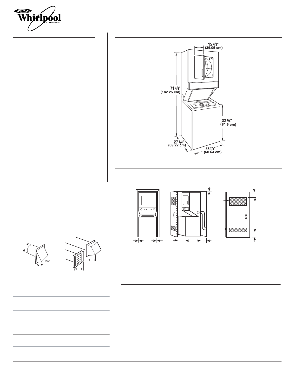
PRODUCT MODEL NUMBER OVERALL DIMENSIONS
RECESSED AREA AND CLOSET INSTALLATION
EXHAUST VENTING
LTG5243D
Gas supply: Dryer is equipped for use with
NATURAL gas. Dryer can be converted to L.P. gas.
When rigid pipe is used it should be 1/2 inch IPS.
When acceptable to the gas supplier and local
codes, 3/8-inch approved tubing may be used for
lengths under 20 feet. For lengths over 20 feet,
larger tubing should be used. Pipe-joint
compounds resistant to the action of L.P. gas must
be used. This washer/dryer is equipped with its
own permanent, flexible gas connector, designcertified by CSA International, for connecting the
appliance to the gas supply line. An individual
manual shutoff valve must be installed within 6
feet of the dryer in accordance with the National
Fuel Gas Code ANSI Z223.1.
Electrical: A 120-volt, 60 Hz, AC-only, electrical
supply is required. 15 or 20 amp fused circuit. A
separate circuit serving only this appliance and a
time-delay fuse or circuit breaker is recommended.
Exhaust venting: Exhaust your dryer to the
outside. Four-inch diameter vent is required. Rigid
or flexible metal exhaust vent must be used. Do
Not use plastic or metal foil vent. Exhaust outlet
hood must be at least 12 inches from the ground
or any object that may be in the path of the
exhaust. The dryer can be converted to exhaust
out right or left side.
Because Whirlpool Corporation policy includes a continuous commitment to improve
our products, we reserve the right to change materials and specifications without notice.
Dimensions are for planning purposes only. For complete details, see Installation
Instructions packed with product. Specifications subject to change without notice.
Ref. 8562591 Rev. A
11-01-04
Plan installation to use the fewest number of elbows
and turns.
Maximum length of the exhaust system depends
upon the type of vent used, number of elbows and
the type of exhaust hood. The maximum length for
both rigid and flexible vent is shown in the chart.
Additional clearance for wall, door and floor molding may be required.
Rear clearance may be 0 in. when house exhaust system is lined up directly with dryer exhaust.
*
A. Recessed area
B. Side view - closet or confined area
C. Closet door with vents
0"
0"
3"
3"
48 in.
24 in.
27237/
8
1
/
4
"
51/2"
1" "
(0 cm)
(0 cm)
(2.5 cm)
(60.64 cm)
(69.22 cm)
(14 cm)
(7.6 cm)
(7.6 cm)
(310 cm )
(155 cm )
2
2
2
2
0"
(0 cm)
Vent Length Chart
NOTE:
Side exhaust adds a 90° turn inside the washer/dryer. To
determine maximum exhaust length, add one 90° turn to the
chart.
Number of
90∫ turns
or elbows
Type of Vent Box or
Louvered
hoods
Angled
hoods
0 Rigid metal
Flexible metal
43 ft (13.1 m)
30 ft (9.1 m)
36 ft (11.0 m)
24 ft (7.3 m)
1 Rigid metal
Flexible metal
33 ft (10.1 m)
24 ft (7.3 m)
26 ft (7.9 m)
18 ft (5.5 m)
2 Rigid metal
Flexible metal
24 ft (7.3 m)
16 ft (4.9 m)
16 ft (4.9 m)
10 ft (3.0 m)
Angled hood style
* Most installations require a
minimum 5-1/2 in. (14 cm)
clearance behind the dryer for
the exhaust vent with elbow.
DRAIN SYSTEM
Standpipe drain system - wall or floor
The standpipe drain requires a minimum diameter standpipe of 2" (5 cm). The minimum carry-away
capacity can be no less than 17 gal. (64 L) per minute. A 2” (5 cm) diameter to 1" (2.5 cm) diameter
standpipe adapter kit is available.
The top of the standpipe must be at least 39" (99 cm) high and no higher than 96" (2.4 m) from the
bottom of the washer.
Laundry tub drain system
The laundry tub needs a minimum 20 gal. (76 L) capacity. The top of the laundry tub must be at least
34" (86.4 cm) above the floor and no higher than 96" (2.4 m) from the bottom of the washer.
Floor drain system
The floor drain system requires a siphon break that may be purchased separately.
The siphon break must be a minimum of 28" (71 cm) from the bottom of the washer. Additional hoses
might be needed.
A. Louvered hood style
B. Box hood style
A
B
A B C
2
4"
(10.2 cm)
(6.4 cm)
1
4"
(10.2 cm)
4"
(10.2 cm)
 Loading...