

Whirlpool LFB2611LQ, LFB2611LT Installation Instructions
IRONING STATION INSTALLATION INSTRUCTIONS
STATION DE REPASSAGE - INSTRUCTIONS
D'INSTALLATION
Table of Contents Table des matières
IRONING STATION SAFETY .........................................................1
INSTALLATION REQUIREMENTS................................................2
Tools and Parts ............................................................................2
Location Requirements................................................................2
Electrical Requirements ...............................................................3
INSTALLATION INSTRUCTIONS..................................................3
Unpack Ironing Station ................................................................3
Cabinet Mounting.........................................................................3
Recessed Mounting .....................................................................5
Make Electrical Connections .......................................................6
Install Door (optional) ...................................................................7
IRONING STATION SAFETY
SÉCURITÉ DE LA STATION DE REPASSAGE.............................8
EXIGENCES D’INSTALLATION.....................................................8
Outillage et pièces........................................................................8
Emplacement d'installation..........................................................9
Spécifications électriques ............................................................9
INSTRUCTIONS D'INSTALLATION.............................................10
Déballage de la station de repassage .......................................10
Montage dans un placard ..........................................................10
Montage dans un encastrement ...............................................12
Raccordements électriques .......................................................14
Installation de la porte (option)...................................................15
Your safety and the safety of others are very important.
We have provided many important safety messages in this manual and on your appliance. Always read and obey all
safety messages.
This is the safety alert symbol.
This symbol alerts you to potential hazards that can kill or hurt you and others.
All safety messages will follow the safety alert symbol and either the word “DANGER” or
“WARNING.” These words mean:
You can be killed or seriously injured if you don't
immediately follow instructions.
can be killed or seriously injured if you don't
You
follow instructions.
All safety messages will tell you what the potential hazard is, tell you how to reduce the chance of injury, and tell you
what can
8537104A
happen if the instructions are not followed.

Location Requirements
You must verify the default position of the ironing board before
installing the ironing center. Refer to the Ironing Board Height
Chart following for the proper height of the various installation
configurations.
Ironing Board Height Chart
Tip Over Hazard
Ironing station is top heavy and tips easily when
not completely installed.
Use two or more people to move and install
ironing station.
Failure to do so can result in serious injury
or cuts.
INSTALLATION
REQUIREMENTS
Tools and Parts
Assemble the required tools and parts before starting installation.
Read and follow the instructions provided with any tools listed
here.
Tools Needed
■ Stud finder (optional) ■ Tape measure
Dimensions shown reflect mounting height above floor level.
(Mount cabinet above floor)
Desired board height range Lower shelf
38 in. (96.5 cm) to 42 in. (106.7 cm)
37 in. (94 cm) to 41 in. (104.1 cm)
36 in. (91.4 cm) to 40 in. (101.6 cm)
35 in. (88.9 cm) to 39 in. (99.1 cm)
34 in. (86.4 cm) to 38 in. (96.5 cm)
33 in. (83.8 cm) to 37 in. (94 cm)
32 in. (81.3 cm) to 36 in. (91.4 cm)
31 in. (78.7 cm) to 35 in. (88.9 cm)
30 in. (76.2 cm) to 34 in. (86.4 cm)
29 in. (73.7 cm) to 33 in. (83.8 cm)
28 in. (71.1 cm) to 32 in. (81.3 cm)
NOTE: The user can adjust height of board after installation with
a 4 in. (10.2 cm) differential between maximum and minimum
heights.
mounting height
above floor
30 in. (76.2 cm)
29 in. (73.7 cm)
28 in. (71.1 cm)
27 in. (68.6 cm)
26 in. (66 cm)
25 in. (63.5 cm)
24 in. (61 cm)
23 in. (58.4 cm)
22 in. (58.9 cm)
21 in. (53.3 cm)
20 in. (50.8 cm)
Installation Clearances
The ironing station board swivels in both directions. To ensure the
board is able to swing into position properly, allow 24 in. (61 cm)
on each side of the board.
■ Carpenter’s level ■ Drill (electric
recommended)
■ Phillips screwdriver ■ Safety glasses
■ Small Phillips screwdriver ■ ¹⁄₄ in. drill bit
■ ¹⁄₁₆ in. drill bit (for
mounting optional door
kit)
Parts Supplied
Look for the small pouch attached to the bottom bar of the
ironing board. This pouch contains the supplied parts.
■ 5 #12 x 1¹/₂ in. screws for cabinet and recessed installation.
■ 3 lag screws for surface installation.
Parts Needed
■ 40w candelabra-style light bulb
■ Filler trim strips for cabinet mounting
24" (61 cm)
24"
(61 cm)
24" (61 cm)
2

Use hinges mounted on the exterior to allow the door to swing
open as fully as possible and to allow the board to swivel.
Electrical Requirements
■ All electrical work must be done in accordance with all
applicable electrical codes.
■ Dedicated 120 Volt AC GFCI Circuit must be used for direct
wire.
■ UL or CSA approved strain relief.
1
1. Automatic cutoff switch
Cabinet Mounting
WARNING
Electrical Shock Hazard
Disconnect power before servicing.
Replace all parts and panels before operating.
Failure to do so can result in death or
electrical shock.
Strain relief
INSTALLATION
INSTRUCTIONS
Choose the installation mode desired: cabinet mounting, or
recessed mounting.
Unpack Ironing Station
WARNING
Excessive Weight Hazard
Use two or more people to move and install
ironing station.
Failure to do so can result in back or other injury.
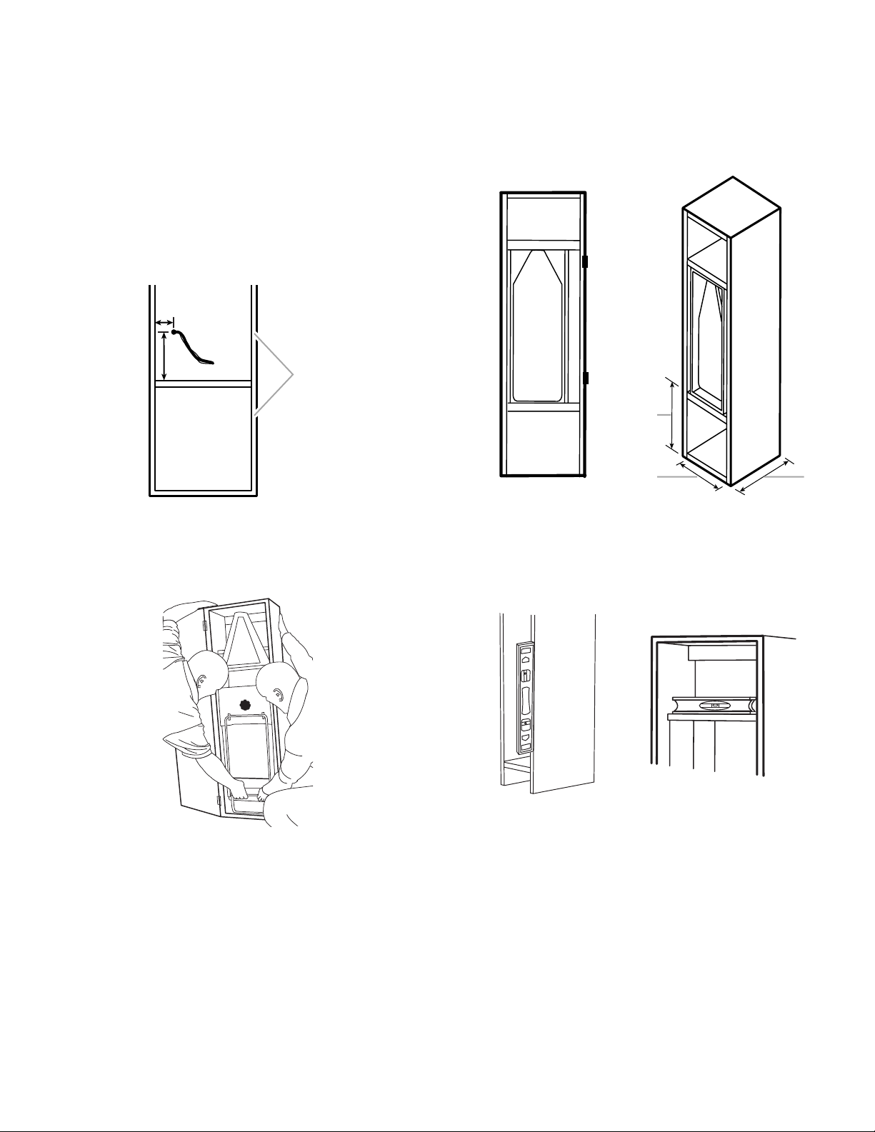
The dimensions of the ironing station unit are 14³/₈ in. (36.6 cm) x
47¹/₂ in. (120.7 cm) x 11¹/₂ in. (29.2 cm).
1. Drill ¹/₄ in. pilot holes in a triangular pattern in the top of the
ironing station box as shown in the following graphic.
NOTE: Drill slowly or add a backing piece to prevent chipping
of the cabinet interior.
67/8" (17.5 cm)
3"
(7.6 cm)
TOP
3
/4"
7
(19.7 cm)
(17.8 cm)
(7.6 cm)
7"
3"
FRONT
2. Drill ¹/₄ in. pilot holes in the bottom of the ironing station box
as shown in the following graphic.
BOTTOM
After removing the ironing station from the carton, locate the
automatic cutoff switch and remove the protective foam
covering.
3"
(7.6 cm)
73/4"
(19.7 cm)
FRONT
3"
(7.6 cm)
3"
(7.6 cm)
3
3. Remove the two screws from the cover of the electrical
3
junction box located in the bottom section of the cabinet.
NOTE: Pigtails are provided inside the junction box located
underneath the lower shelf for hookup to the supply line.
4. Remove the knockout for the appropriate wiring entrance
location.
NOTE: For cabinet mounting, the wiring will enter from the
back of the ironing station unit.
5. Before putting the unit into place, install a strain relief in the
location where the knockout was removed.
6. Make sure the supply wire is in a location to thread through
the wiring opening in the ironing station approximately 4³/₄ in.
(12.2 cm) from the bottom of the unit. A free wire length of 5 ft
(152.4 cm) is recommended.
1
/8"
2
(5.3 cm)
43/4"
(12.2 cm)
1
9. Place the ironing station box inside the cabinet and slide it to
the side wall opposite the hinges and flush with the front of
the cabinet. Feed the wiring through the strain relief while
sliding the unit into the cabinet.
NOTE: Filler trim strips may be added to cover any open
space left after the unit is in place in the cabinet.
1
1. Cabinet
7. Begin installation by picking up the ironing station unit with
one hand grasping the bottom bar of the ironing board and
the other hand on the top back of the ironing station.
8. As you are placing the ironing station into its location, feed
the wire through the strain relief.
2
1. Nominal height - 26 in. (66 cm)
2. Minimum inside dimension - 17.4 in. (44.1 cm)
3. Depth - 24 in. (61 cm) or 12 in. (30.5 cm) minimum
10. Check to see whether the ironing station is level by placing a
level against the front face and top shelf of the unit.
NOTE: Shim the bottom of the unit to make the top of the unit
reach the underside of the top cabinet shelf. If it is not level,
correct by further shimming.
11. Mount the unit to the top shelf using three #12 x 1¹⁄₂ in.
Phillips screws in a triangular pattern. When screwing the
screws into the top shelf, screw in the two front screws first.
When they are in place, screw in the third screw.
12. Mount the unit to the bottom shelf using two #12 x 1¹⁄₂ in.
Phillips screws.
4
13. Use the exterior mounted hinges to allow the door to swing at
a wider angle and to allow the board to swivel.
NOTE: Swiveling of the board may be restricted depending
on the type of door hinge used.
14. See “Make Electrical Connections” section for final wiring
directions.
Recessed Mounting
WARNING
Electrical Shock Hazard
Disconnect power before servicing.
Replace all parts and panels before operating.
Failure to do so can result in death or
electrical shock.
The ironing station unit extends into the room approximately
7¹⁄₂ in. (19.1 cm).
1. Determine the desired ironing board height above the floor
using the chart in the “Location Requirements” section. Care
should be taken to ensure the unit will be mounted at the
ironing board height desired.
2. Using a stud finder, locate the wall studs to be used for
mounting.
3. Locate the existing wiring in the wall to prevent drilling into or
severing a wire or other hidden utilities during drilling.
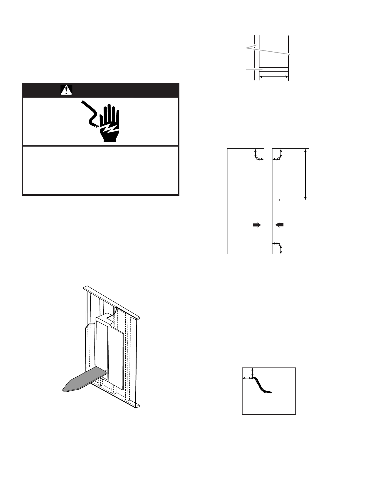
4. Cut a hole in the drywall large enough for the ironing station
to fit. The dimensions of the ironing station unit are 14¹/₂ in.
(36.8 cm) x 47¹/₂ in. (120.7 cm) x 11¹/₂ in. (29.2 cm).
6. Attach 2 in. (5.1 cm) x 4 in. (10.2 cm) cross supports between
the studs, level with the the bottom of the opening.
1
2
16"
(40.6 cm)
1. Studs
2. Cross support - 2 in. x 4 in.
(5.1 cm x 10.2 cm)
7. Shim the side walls to match the width of the ironing station.
8. Using a ¹/₄ in. drill bit, predrill the pilot holes through the unit
frame as indicated in the graphic below.
NOTE: Drill slowly or add backing piece to prevent chipping
of the cabinet interior.
LEFT SIDE
INTERIOR
(5.1 cm)
(3.8 cm)
BACK
2"
11/2"
2"
(5.1 cm)
11/2"
(3.8 cm)
11/2"
(3.8 cm)
2"
(5.1 cm)
1
18
(47 cm)
BACK
/2"
RIGHT SIDE
INTERIOR
9. Remove the two screws from the cover of the electrical
junction box located in the bottom section of the cabinet.
NOTE: Pigtails are provided inside of the junction box located
underneath the lower shelf for hookup to the supply line.
10. Remove the knockout for the appropriate wiring entrance
location.
NOTE: For recessed mounting, the wiring will enter from the
bottom of the ironing station unit.
11. Before putting the unit into place, install a strain relief in the
location where the knockout was removed.
12. Make sure the supply wire is in a location to thread through
the wiring opening in the ironing station approximately from
the bottom of unit. A free wire length of 5 ft (152.4 cm) is
recommended.
BACK
21/8" (5.3 cm)
21/8"
(5.3 cm)
5. Allow at least 16 in. (40.6 cm) to the side of the unit for the
door to swing open. Door opens approximately 180 degrees.
See “Install Door.”
FRONT
5
 Loading...