

Whirlpool LFB2611L User Manual
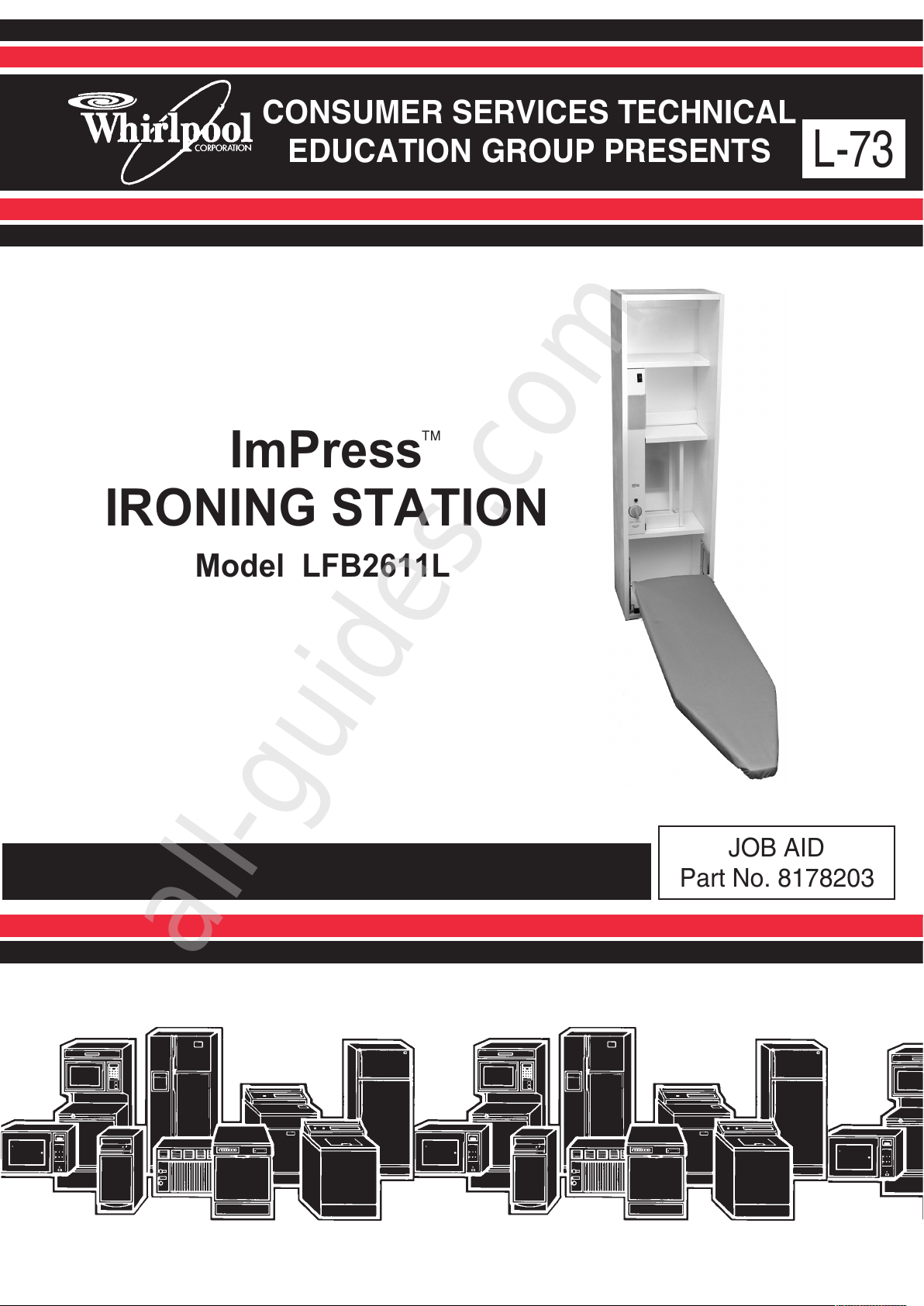
CONSUMER SERVICES TECHNICAL
EDUCATION GROUP PRESENTS
L-73
JOB AID
Part No. 8178203
Model LFB2611L
ImPress
IRONING STATION
All manuals and user guides at all-guides.com
all-guides.com
WHIRLPOOL CORPORATION assumes no responsibility for any repairs made
on our products by anyone other than Authorized Service Technicians.
FORWARD
This Whirlpool Job Aid, “ImPress Ironing Station,” (Part No. 8178203), provides the technician
with information on the installation, operation, and service of the ImPress
Ironing Station. It is
to be used as a training Job Aid and Service Manual.
The Wiring Diagram used in this Job Aid is typical and should be used for training purposes only.
Always use the Wiring Diagram supplied with the product when servicing the unit.
GOALS AND OBJECTIVES
The goal of this Job Aid is to provide detailed information that will enable the service technician to
properly diagnose malfunctions and repair the Whirlpool ImPress
Ironing Station.
The objectives of this Job Aid are to:
• Understand and follow proper safety precautions.
• Successfully troubleshoot and diagnose malfunctions.
• Successfully perform necessary repairs.
• Successfully return the Ironing Station to its proper operational status.
Copyright © 2002, Whirlpool Corporation, Benton Harbor, MI 49022
- ii -
All manuals and user guides at all-guides.com
TABLE OF CONTENTS
GENERAL............................................................................................................................... 1-1
Safety First......................................................................................................................... 1-1
Model & Serial Number Designations ................................................................................ 1-2
Model & Serial Number Label And Wiring Diagram Locations .......................................... 1-3
Specifications..................................................................................................................... 1-4
Whirlpool ImPress Ironing Station Warranty ...................................................................... 1-5
INSTALLATION INFORMATION ........................................................................................... 2-1
Surface Mounting............................................................................................................... 2-1
PRODUCT OPERATION ........................................................................................................ 3-1
Adjusting The Board Height ............................................................................................... 3-1
Adjusting The Swivel Tension............................................................................................ 3-1
The Work Light .................................................................................................................. 3-1
Using The Iron ................................................................................................................... 3-2
Storing The Ironing Board.................................................................................................. 3-2
COMPONENT ACCESS ......................................................................................................... 4-1
Removing The Light Socket, Indicator Light, Timer,
AC Receptacle, & Cutoff Switch ..................................................................................... 4-1
COMPONENT TESTING ........................................................................................................ 5-1
Timer.................................................................................................................................. 5-1
Cutoff Switch...................................................................................................................... 5-2
WIRING DIAGRAM................................................................................................................. 6-1
Page
- iii -
All manuals and user guides at all-guides.com

- iv -
— NOTES —
All manuals and user guides at all-guides.com
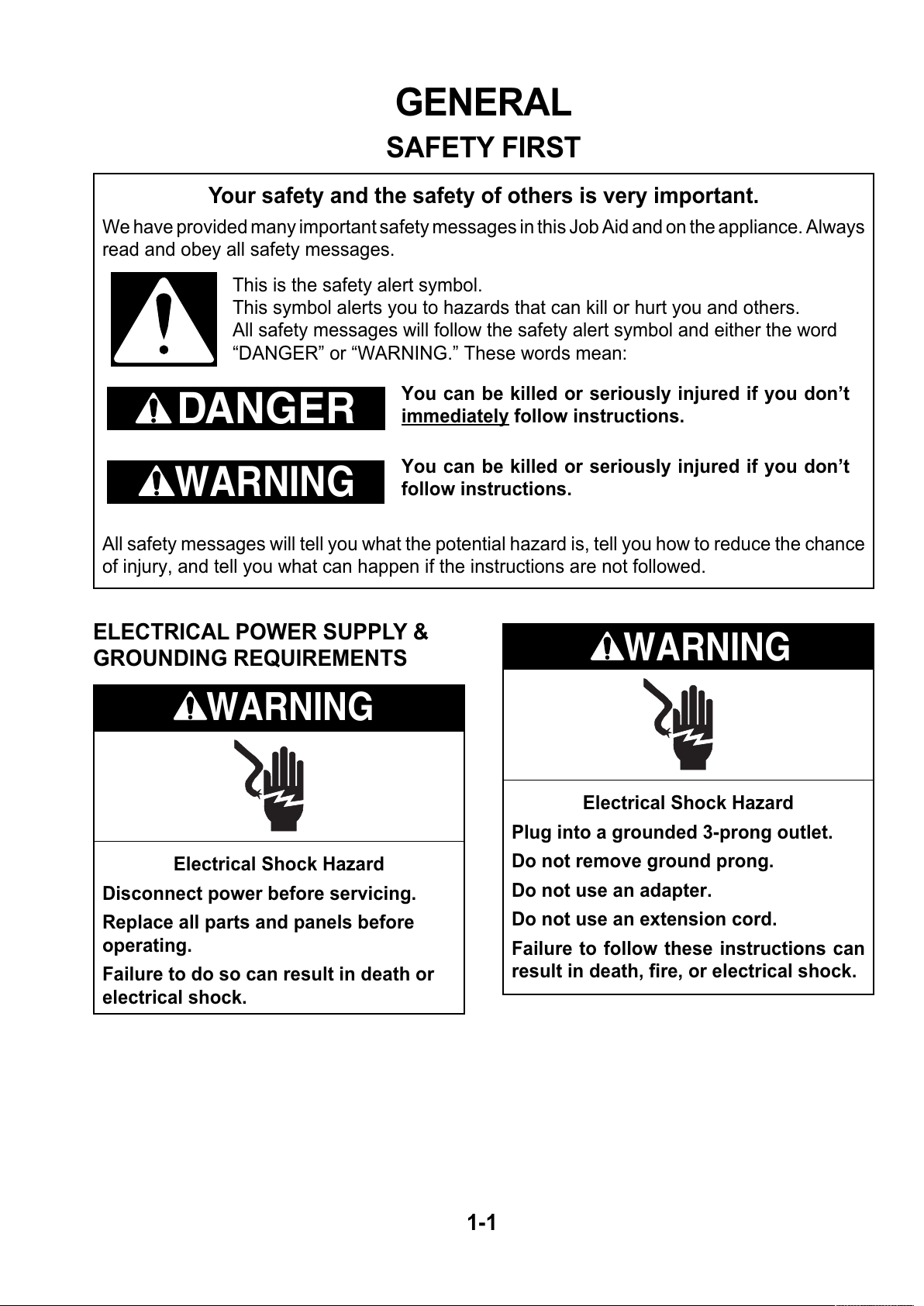
Electrical Shock Hazard
Plug into a grounded 3-prong outlet.
Do not remove ground prong.
Do not use an adapter.
Do not use an extension cord.
Failure to follow these instructions can
result in death, fire, or electrical shock.
Electrical Shock Hazard
Disconnect power before servicing.
Replace all parts and panels before
operating.
Failure to do so can result in death or
electrical shock.
GENERAL
SAFETY FIRST
Your safety and the safety of others is very important.
We have provided many important safety messages in this Job Aid and on the appliance. Always
read and obey all safety messages.
This is the safety alert symbol.
This symbol alerts you to hazards that can kill or hurt you and others.
All safety messages will follow the safety alert symbol and either the word
“DANGER” or “WARNING.” These words mean:
DANGER
WARNING
All safety messages will tell you what the potential hazard is, tell you how to reduce the chance
of injury, and tell you what can happen if the instructions are not followed.
You can be killed or seriously injured if you don’t
immediately follow instructions.
You can be killed or seriously injured if you don’t
follow instructions.
ELECTRICAL POWER SUPPLY &
GROUNDING REQUIREMENTS
WARNING
WARNING
1-1
All manuals and user guides at all-guides.com
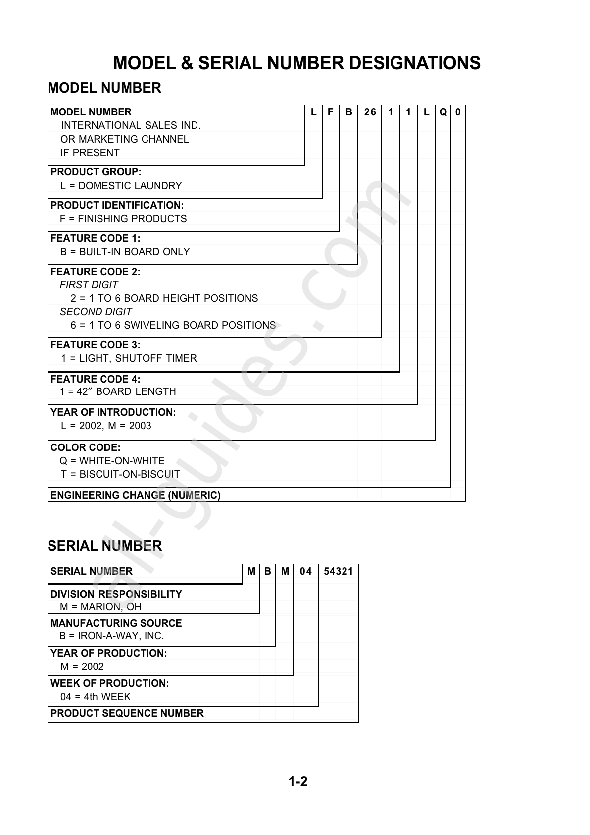
MODEL & SERIAL NUMBER DESIGNATIONS
MODEL NUMBER
SERIAL NUMBER
1-2
MODEL NUMBER L F B 26 1 1 L Q 0
INTERNATIONAL SALES IND.
OR MARKETING CHANNEL
IF PRESENT
PRODUCT GROUP:
L = DOMESTIC LAUNDRY
PRODUCT IDENTIFICATION:
F = FINISHING PRODUCTS
FEATURE CODE 1:
B = BUILT-IN BOARD ONLY
FEATURE CODE 2:
FIRST DIGIT
2 = 1 TO 6 BOARD HEIGHT POSITIONS
SECOND DIGIT
6 = 1 TO 6 SWIVELING BOARD POSITIONS
FEATURE CODE 3:
1 = LIGHT, SHUTOFF TIMER
FEATURE CODE 4:
1 = 42″ BOARD LENGTH
YEAR OF INTRODUCTION:
L = 2002, M = 2003
COLOR CODE:
Q = WHITE-ON-WHITE
T = BISCUIT-ON-BISCUIT
ENGINEERING CHANGE (NUMERIC)
SERIAL NUMBER M B M 04 54321
DIVISION RESPONSIBILITY
M = MARION, OH
MANUFACTURING SOURCE
B = IRON-A-WAY, INC.
YEAR OF PRODUCTION:
M = 2002
WEEK OF PRODUCTION:
04 = 4th WEEK
PRODUCT SEQUENCE NUMBER
All manuals and user guides at all-guides.com
all-guides.com
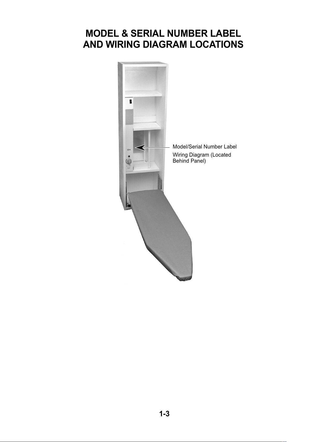
MODEL & SERIAL NUMBER LABEL
AND WIRING DIAGRAM LOCATIONS
1-3
Model/Serial Number Label
Wiring Diagram (Located
Behind Panel)
All manuals and user guides at all-guides.com
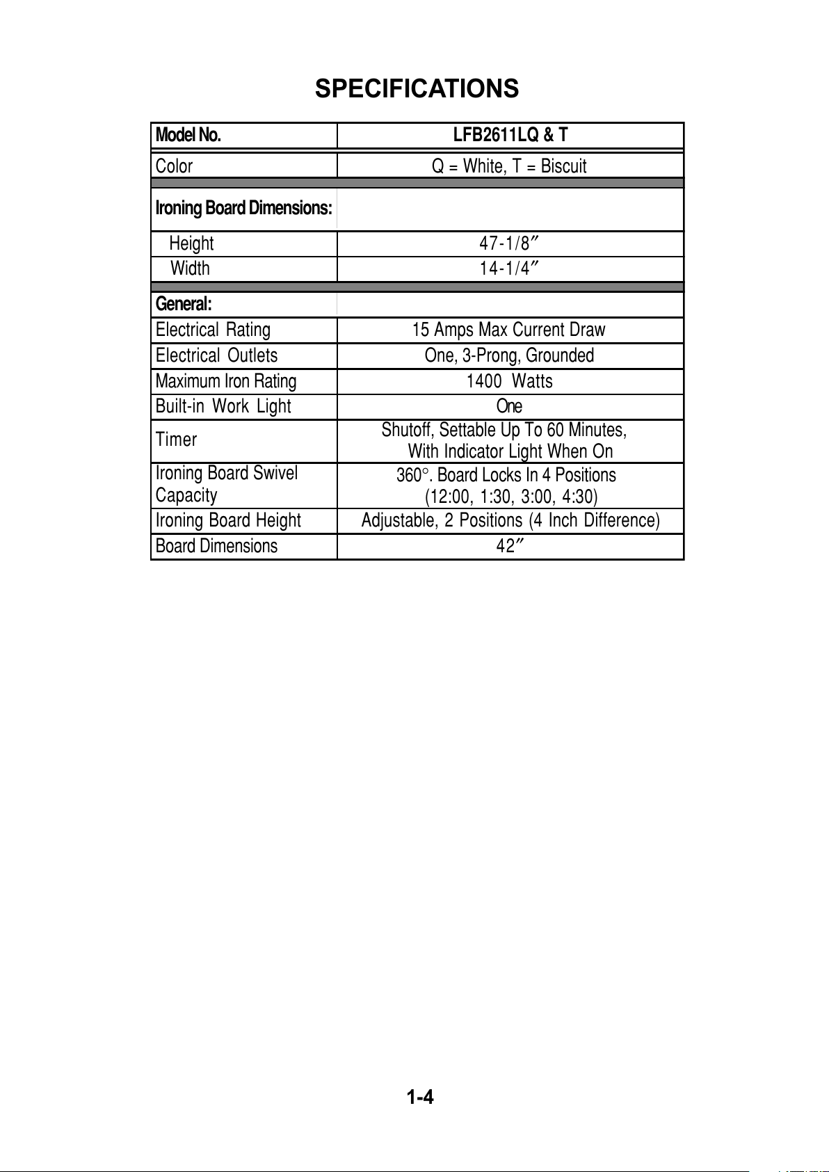
SPECIFICATIONS
1-4
Model No. LFB2611LQ & T
Color Q = White, T = Biscuit
Ironing Board Dimensions:
Height 47-1/8″
Width 14-1/4″
General:
Electrical Rating 15 Amps Max Current Draw
Electrical Outlets One, 3-Prong, Grounded
Maximum Iron Rating 1400 Watts
Built-in Work Light One
Timer
Shutoff, Settable Up To 60 Minutes,
With Indicator Li
g
ht When On
Ironing Board Swivel
Capacity
360°. Board Locks In 4 Positions
(
12:00, 1:30, 3:00, 4:30
)
Ironing Board Height Adjustable, 2 Positions (4 Inch Difference)
Board Dimensions 42″
All manuals and user guides at all-guides.com
 Loading...