

Whirlpool LDR3822PQ User Manual
®
120-VOLT ELECTRIC
COMPACT DRYER
Use & Care Guide
For questions about features, operation/performance
parts, accessories, or service, call: 1-800-253-1301
In Canada, call 1-800-807-6777
www.whirlpool.com or www.whirlpool.ca
or visit our website at...
SÉCHEUSE ÉLECTRIQUE
COMPACTE 120 VOLTS
Guide d’utilisation
et d’entretien
Pour des questions à propos des caractéristiques, du
fonctionnement, de la performance, des pièces, accessoires
ou service, composez le 1-800-807-6777
ou visitez notre site web à
www.whirlpool.ca
8578198C
Table of Contents/Table des matières.................. 2
TABLE OF CONTENTS
TABLE DES MATIÈRES
DRYER SAFETY..............................................................................2
INSTALLATION INSTRUCTIONS..................................................4
Tools and Parts ............................................................................4
Location Requirements................................................................4
Electrical Requirements ...............................................................5
Venting Requirements..................................................................6
Plan Vent System.........................................................................6
Install Vent System.......................................................................7
Install Cord Bracket and Casters.................................................8
Connect Vent................................................................................8
Complete Installation ...................................................................8
DRYER USE ....................................................................................9
Starting Your Dryer.......................................................................9
Stopping and Restarting...................................
Loading.......................................................................................10
Drying, Cycle, and Temperature Tips ........................................10
Cycles.........................................................................................10
DRYER CARE ...............................................................................11
Cleaning the Dryer Location ......................................................11
Cleaning the Lint Screen............................................................11
Cleaning the Dryer Interior .........................................................11
Removing Accumulated Lint......................................................12
Vacation and Moving Care.........................................................12
TROUBLESHOOTING ..................................................................12
ASSISTANCE OR SERVICE.........................................................13
WARRANTY ..................................................................................14
...........................9
SÉCURITÉ DE LA SÉCHEUSE ....................................................15
INSTRUCTIONS D’INSTALLATION............................................16
Outillage et pièces nécessaires .................................................16
Emplacement d’installation .......................................................16
Spécifications électriques ..........................................................17
Exigences concernant l'évacuation ...........................................18
Planification du système d'évacuation ......................................19
Installation du conduit d’évacuation..........................................20
Installation de la bride du cordon et des roulettes ....................20
Conduit d’évacuation .................................................................21
Achever l'installation ..................................................................21
UTILISATION DE LA SÉCHEUSE..................
Mise en marche de la sécheuse ................................................22
Arrêt et remise en marche..........................................................22
Chargement................................................................................23
Conseils pour séchage, programmes et température...............23
Programmes...............................................................................23
ENTRETIEN DE LA SÉCHEUSE..................................................24
Nettoyage de l'emplacement de la sécheuse ...........................24
Nettoyage du filtre à charpie......................................................24
Nettoyage de l'intérieur de la sécheuse.....................................24
Enlever la charpie accumulée ....................................................25
Précautions à prendre pour les vacances et
déménagement ..........................................................................25
DÉPANNAGE.................................................................................25
ASSISTANCE OU SERVICE.........................................................27
GARANTIE.....................................................................................28
..............................22
avant un
DRYER SAFETY
Your safety and the safety of others are very important.
We have provided many important safety messages in this manual and on your appliance. Always read and obey all safety
messages.
This is the safety alert symbol.
This symbol alerts you to potential hazards that can kill or hurt you and others.
All safety messages will follow the safety alert symbol and either the word “DANGER” or “WARNING.”
These words mean:
You can be killed or seriously injured if you don't immediately
DANGER
WARNING
All safety messages will tell you what the potential hazard is, tell you how to reduce the chance of injury, and tell you what can
happen if the instructions are not followed.
follow instructions.
You
can be killed or seriously injured if you don't
instructions.
follow
2
IMPORTANT SAFETY INSTRUCTIONS
WARNING:
including the following:
Read all instructions before using the dryer.
Do not place items exposed to cooking oils in your dryer.
Items contaminated with cookin g oils may contribute to
a chemical reaction that could cause a load to catch fire.
Do not dry articles that have been previously cleaned in,
was hed in, soaked in, or spotted with gasoline, drycleaning solvents, other flammable, or explosive
substances as they give off vapors that could ignite or
explode.
Do not allow children to play on or in the dryer. Close
supervision of children is necessary when the dryer is
used near children.
Befor e the dryer is removed from service or discarded,
remove the door to the drying compartment.
Do not reach into the dryer if the drum is moving.
Do not install or store the dryer where it will be exposed
to the weather.
Do not tamper with controls.
To reduce the risk of fire, electric shock, or injury to persons when using the dryer, follow basic precautions,
SAVE THESE INSTRUCTIONS
Do not repair or replace any part of the dryer or attempt
any servicing unless specifically recommended in this
Use and Care Guide or in published user-repair
instructions that you understand and have the skills to
carry out.
Do not use fabric softeners or products to eliminate static
unless recommended by the manufacturer of the fabric
softener or product.
Do not use heat to dry articles containing foam rubber or
similarly textured rubber-like materials.
Clean lint screen before or after each load.
Keep area around the exhaust opening and adjacent
surrounding areas free from the accumulation of lint, dust,
and dirt.
The interior of the dryer and exhaust vent should be
cleaned periodically by qualified service personnel.
See installation instructions for grounding requirements.
3
INSTALLATION INSTRUCTIONS
Tools and Parts
To o ls n e e d ed
Gather the required tools and parts before starting installation.
Read and follow the safety instructions provided with any tools
listed here.
Flat-blade screwdriver
Level
Adjustable wrench
Vent clamps
Parts supplied
Remove parts package from the dryer drum. Check that all parts
listed are included.
1 - Cycle Control (timer)
knob
1 - Push to Start button
4 - casters
Parts needed
Check local codes, existing electrical supply and venting, and
see “Venting Requirements” and “Electrical Requirements”
before purchasing parts.
Mobile home installations require metal exhaust system
hardware
Permanent installations require 4 dryer feet
For ordering information, please reference the “Assistance or
Service” section of this manual. You can also contact the dealer
from whom you purchased your dryer.
Caulking gun and
compound (for installing
new exhaust vent)
Tin snips (new vent
installations)
2 - cord brackets
2-screws
A grounded electrical outlet located within 2 ft (610 mm)
of either side of the dryer. See “Electrical Requirements.”
A sturdy floor to support the dryer weight (dryer and load)
of 115 lbs (52 kg). The combined weight of a companion
appliance should also be considered.
A level floor with a maximum slope of 1" (25 mm) under entire
dryer.
Do not operate your dryer at temperatures below 45ºF (7ºC). At
lower temperatures, the dryer might not shut off at the end of an
automatic cycle. Drying times can be extended.
The dryer must not be installed or stored in an area where it will
be exposed to water and/or weather.
Check code requirements. Some codes limit, or do not permit,
installation of the dryer in garages, closets, mobile homes, or
sleeping
quarters. Contact your local building inspector.
Installation Clearances
The location must be large enough to allow the dryer door to
open fully.
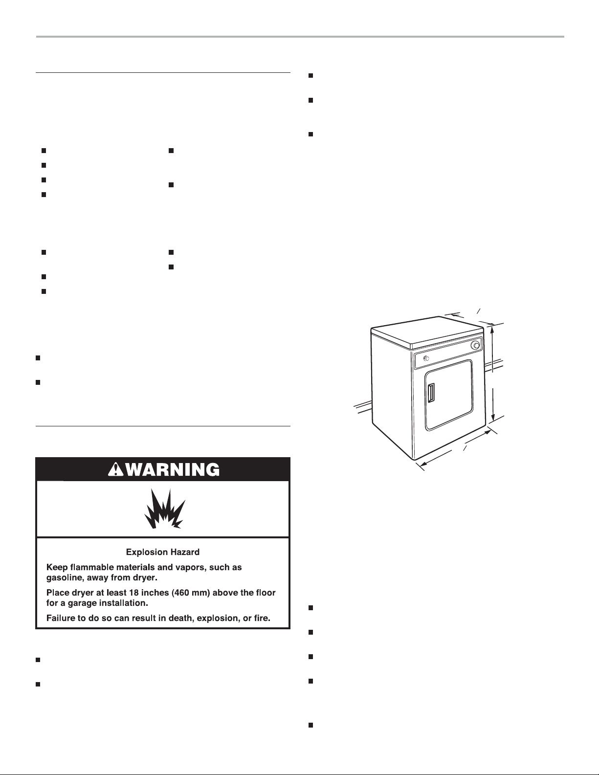
Dryer Dimensions
3
20
4
"
*
(527 mm)
†
31"
(787 mm)
Location Requirements
You will need
A location that allows for proper exhaust installation. See
“Venting Requirements.”
A 120-volt, 60-hz., AC-only, 15- or 20-amp circuit.
7
23
8
"
(606 mm)
†Height with caster is 32½" (826 mm)
*Most installations require a minimum 5½" (140 mm) clearance
behind the dryer for the exhaust vent with elbows. See “Venting
Requirements.”
Minimum installation spacing for recessed area and closet
installation
The following dimensions shown are for the minimum spacing
allowed when the unit is to be
Stack Stand Kit. To purchase a Stack Stand Kit, see “Assistance
or Service.”
Additional spacing should be considered for ease of
installation and servicing.
Additional clearances might be required for wall, door, and
floor moldings.
Additional spacing of 1" (25 mm) on all sides of the dryer
is recommended to reduce noise transfer.
For closet installation with a door, minimum ventilation
openings in the top and bottom of the door are required.
Louvered doors with equivalent ventilation openings are
acceptable.
Companion appliance spacing should also be considered.
operated with, or without, the
4
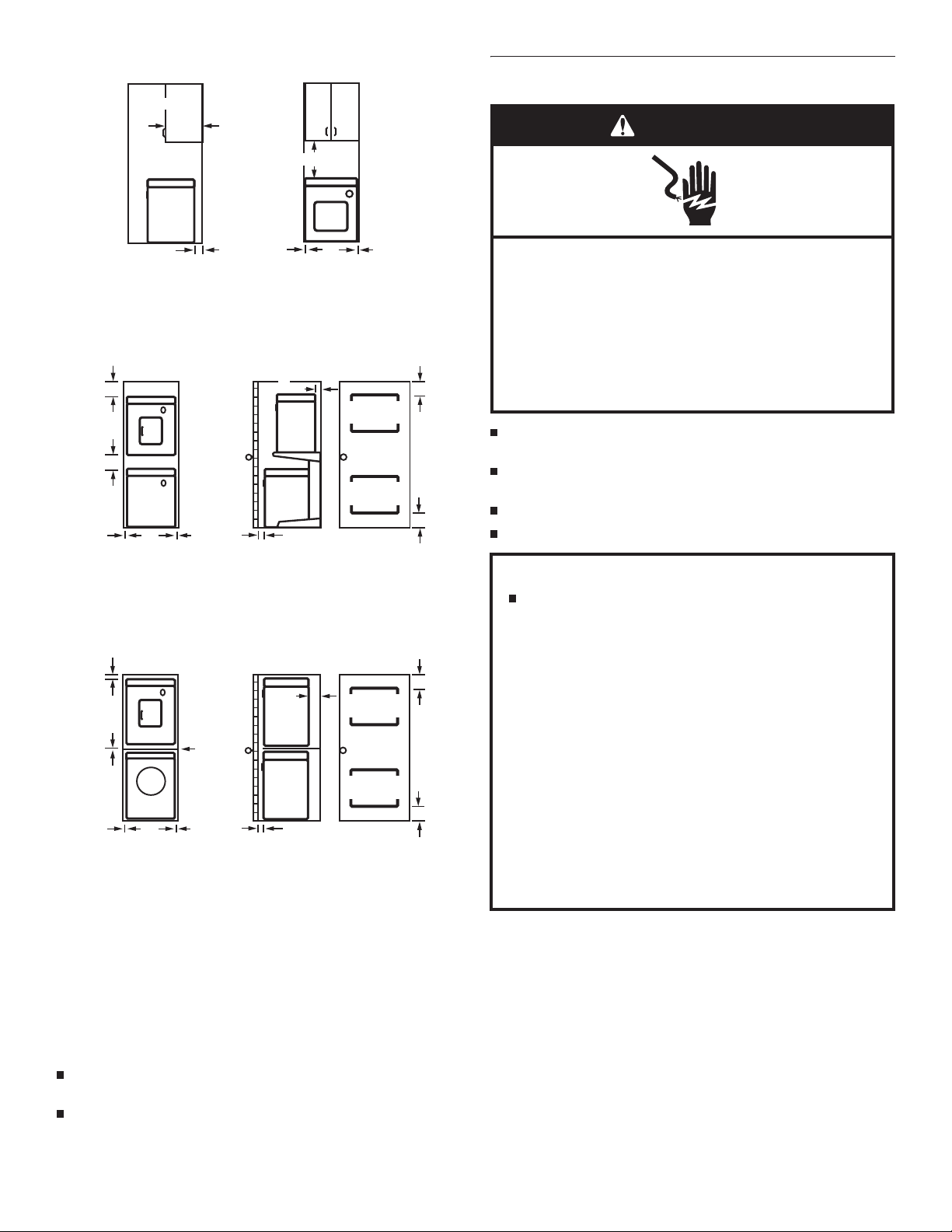
Recessed or closet installation - Dryer only
14"
(356 mm)
18"(457 mm)
Electrical Requirements
WARNING
3"
(76 mm)
0"
(0 mm)
0"
(0 mm)
BA
A. Side view - closet or conned area
B. Recessed area
Recessed or closet installation - Stacked
12"
(305 mm)
12"
(305 mm)
0"
(0 mm)
DRYER
WASHER
0"
(0 mm)
1"
(25 mm)
A. Recessed area
B. Side view - closet or conned area
C. Closet door with vents
3"
(76 mm)
48 in.
(309.7 cm )
(154.8 cm )
BA
Closet installation with WFC7500VW - Stacked
2"
1"
(25 mm)
0"
(0 mm)
0"
(0 mm)
DRYER
SHELF
WASHER
0"
(0 mm)
1"
(25 mm)
A. Recessed area
B. Side view - closet or conned area
C. Closet door with vents
(51 mm)
BA
48 in.
(309.7 cm )
(154.8 cm )
24 in.
C
24 in.
C
Electrical Shock Hazard
Plug into a grounded 3 prong outlet.
Do not remove ground prong.
Do not use an adapter.
Do not use an extension cord.
3"
(76 mm)
2
2
Failure to follow these instructions can result in death,
re, or electrical shock.
A 120-volt, 60-Hz., AC-only, 15- or 20-amp fused electrical
supply is required.
2
2
3"
(76 mm)
A time-delay fuse or circuit breaker is recommended. Be sure
fuse or circuit breaker matches the rating of your line.
Use a separate circuit serving only your dryer.
Do not use an extension cord.
GROUNDING INSTRUCTIONS
For a grounded, cord-connected dryer:
This dryer must be grounded. In the event of malfunction or
breakdown, grounding will reduce the risk of electric shock
by providing a path of least resistance for electric current.
3"
(76 mm)
2
2
This dryer is equipped with a cord having an equipmentgrounding conductor and a grounding plug. The plug must
be plugged into an appropriate outlet that is properly
installed and grounded in accordance with all local codes
and ordinances.
2
2
3"
(76 mm)
WARNING: Improper connection of the equipment-
grounding conductor can result in a risk of electric shock.
Check with a qualied electrician or service representative
or personnel if you are in doubt as to whether the dryer is
properly grounded. Do not modify the plug provided with the
dryer: if it will not t the outlet, have a proper outlet installed
by a qualied electrician.
SAVE THESE INSTRUCTIONS
Mobile Home - Additional Location Requirements
This dryer is suitable for mobile home installations. The
installation must conform to the Manufactured Home
Construction and Safety Standard, Title 24 CFR, Part 3280
(formerly the Federal Standard for Mobile Home Construction
and Safety, Title 245, HUD Part 280) or Standard CAN/CSA-Z240
MH.
Mobile home installations require:
Metal exhaust system hardware which is available for
purchase from your dealer.
Special provisions must be made in mobile homes to
introduce outside air into the dryer. The opening (such as a
nearby window) should be at least twice as large as the dryer
exhaust opening.
5
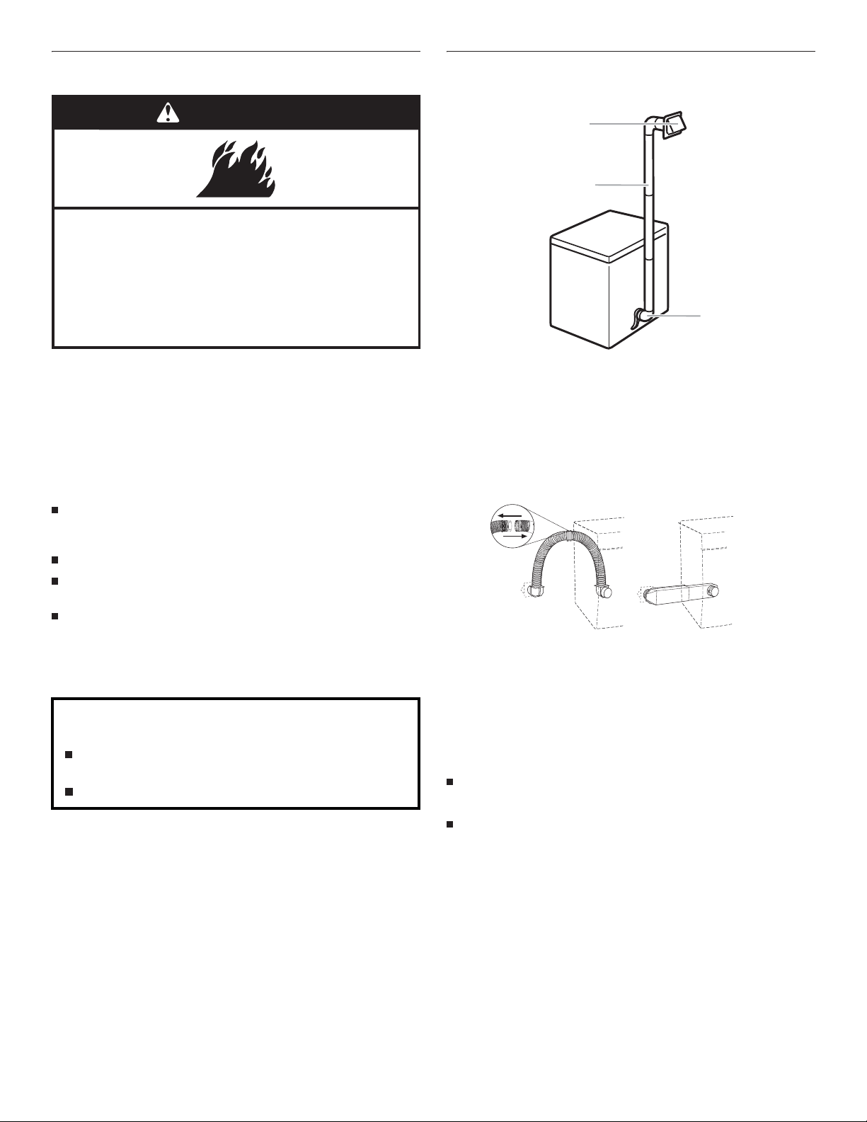
Venting Requirements
C
Plan Vent System
Typical installations vent the dryer from the rear of the dryer.
WARNING
Fire Hazard
Use a heavy metal vent.
Do not use a plastic vent.
Do not use a metal foil vent.
Failure to follow these instructions can result in death
or fire.
WARNING: To reduce the risk of fire, this dryer MUST BE
EXHAUSTED OUTDOORS.
Only rigid or flexible metal duct shall be used for exhausting.
4" (102 mm) heavy metal exhaust vent and clamps must be used.
DURASAFE™ vent products are recommended.
DURASAFE™ vent products can be purchased from your dealer
or by calling Whirlpool Parts and Accessories. For more
information, see the “Assistance or Service” section of this
manual.
The dryer exhaust must not be connected into any gas vent,
chimney, wall, ceiling, attic, crawlspace, or a concealed space
of a building.
Do not use an exhaust hood with a magnetic latch.
Do not install flexible metal vent in enclosed walls, ceilings,
or floors.
Use clamps to seal all joints. Exhaust vent must not be
connected or secured with screws or other fastening devices
which extend into the interior of the duct and catch lint.
Do not use duct tape.
IMPORTANT: Observe all governing codes and ordinances.
Improper venting can cause moisture and lint to collect
indoors, which may result in:
Moisture damage to woodwork, furniture, paint,
wallpaper, carpets, etc.
Housecleaning problems and health problems.
Use a heavy metal vent. Do not use plastic or metal foil vent.
Rigid metal vent is recommended to prevent crushing and kinking.
Flexible metal vent must be fully extended and supported when
the dryer is in its final position. Remove excess flexible metal vent
id sagging and kinking that may result in reduced airflow.
to avo
The total length of flexible metal vent should not exceed
3
7
⁄4 ft (2.4 m).
An exhaust hood should cap the vent to prevent rodents and
insects from entering the home.
Exhaust hood must be at least 12" (305 mm) from the ground
or any object that may be in the path of the exhaust (such as
flowers, rocks or bushes, etc.).
If using an existing vent system, clean lint from the entire length
of the system and make sure exhaust hood is not plugged with
lint. Replace any plas
flexible metal vent.
6
tic or metal foil vent with rigid metal or
A
B
A. Exhaust hood
B. Flexible metal vent or rigid metal vent
C. Elbow
Alternate installations for close clearances
Venting systems come in many varieties. Select the type best
for your installation. Two close-clearance installations are shown.
Refer to the manufacturer’s instructions provided with the vent
system.
A
A. Over-The-Top installation (also available with
one offset elbow)
B. Periscope installation
NOTE: The following kits for close clearance alternate
installations are available for purchase. For ordering information
see “Assistance or Se
Over-The-Top Installation:
Part Number 4396028
Periscope Installation (for use with dryer vent to wall vent
mismatch):
Part Number 4396037 - for mismatch of 0" (0 mm)
to 18" (457 mm)
Part Number 4396011 - for mismatch of 18" (457 mm)
to 29" (737 mm)
Part Number 4396014 - for mismatch of 29" (737 mm)
to 50" (1.27 m)
rvice.”
B
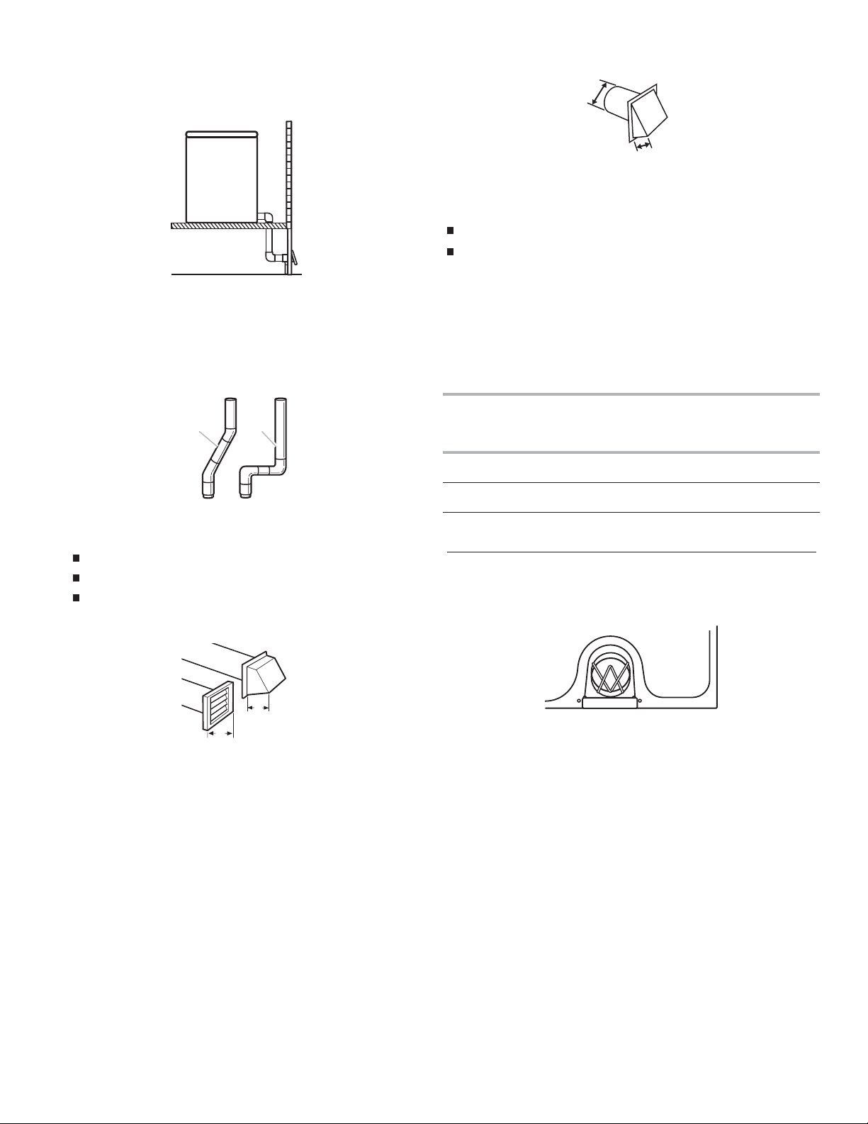
Special provisions for mobile home installations
The exhaust vent must be securely fastened to a noncombustible
portion of the mobile home structure and must not terminate
beneath the mobile home. Terminate the exhaust vent outside.
Determine vent length
1. Select the route that will provide the straightest and most
direct path outdoors. Plan the installation to use the fewest
number of elbows and turns. When using elbows or making
turns, allow as much room as possible. Bend ven
to avoid kinking. Avoid 90° turns when possible.
tgradually
The angled hood style (shown following) is acceptable.
4"
(102 mm)
2½"
(64 mm)
See the exhaust vent length chart that matches your hood type
for the maximum vent lengths you can use.
Exhaust systems longer than specied will:
Shorten the life of the dryer.
Reduce performance, resulting in longer drying times and
increased energy usage.
3. Determine the number of elbows you will need.
IMPORTANT: Do not use vent runs longer than specied in the
Vent Length Chart.
Find the maximum length of metal vent on the same line as the
number of elbows.
Vent Length Chart
better
good
2. Determine vent length.
The maximum length of the exhaust system depends upon:
The type of vent (rigid metal or exible metal).
The number of elbows used.
Type of hood.
Recommended hood styles are shown here.
B
A
4"
(102 mm)
4"
(102 mm)
A. Louvered style
B. Box hood style
Number of
90º turns
or elbows
Type of
vent
Box or
louvered
hoods
Angled
hoods
0 Rigid metal 36 ft (11 m) 26 ft (7.9 m)
1 Rigid metal 26 ft (7.9 m) 16 ft (4.9 m)
2 Rigid metal 16 ft (4.9 m) 6 ft (1.8 m)
Install Vent System
1. Before installing the vent system, be sure to remove the wire
exhaust guard that is located at the exhaust outlet.
2. Install exhaust hood. Use caulking compound to seal exterior
wall opening around exhaust hood.
3. Connect vent to exhaust hood. Vent must t inside exhaust
hood. Secure vent to exhaust hood with 4" (102 mm) clamp.
4. Run vent to dryer location. Use the straightest path possible.
See “Determine vent length.”
seal all joints. Do not use duct tape, screws, or other fastening
devices that extend into the interior of the vent to secure
the vent, because they can catch lint.
Avoid 90º turns. Use clamps to
7
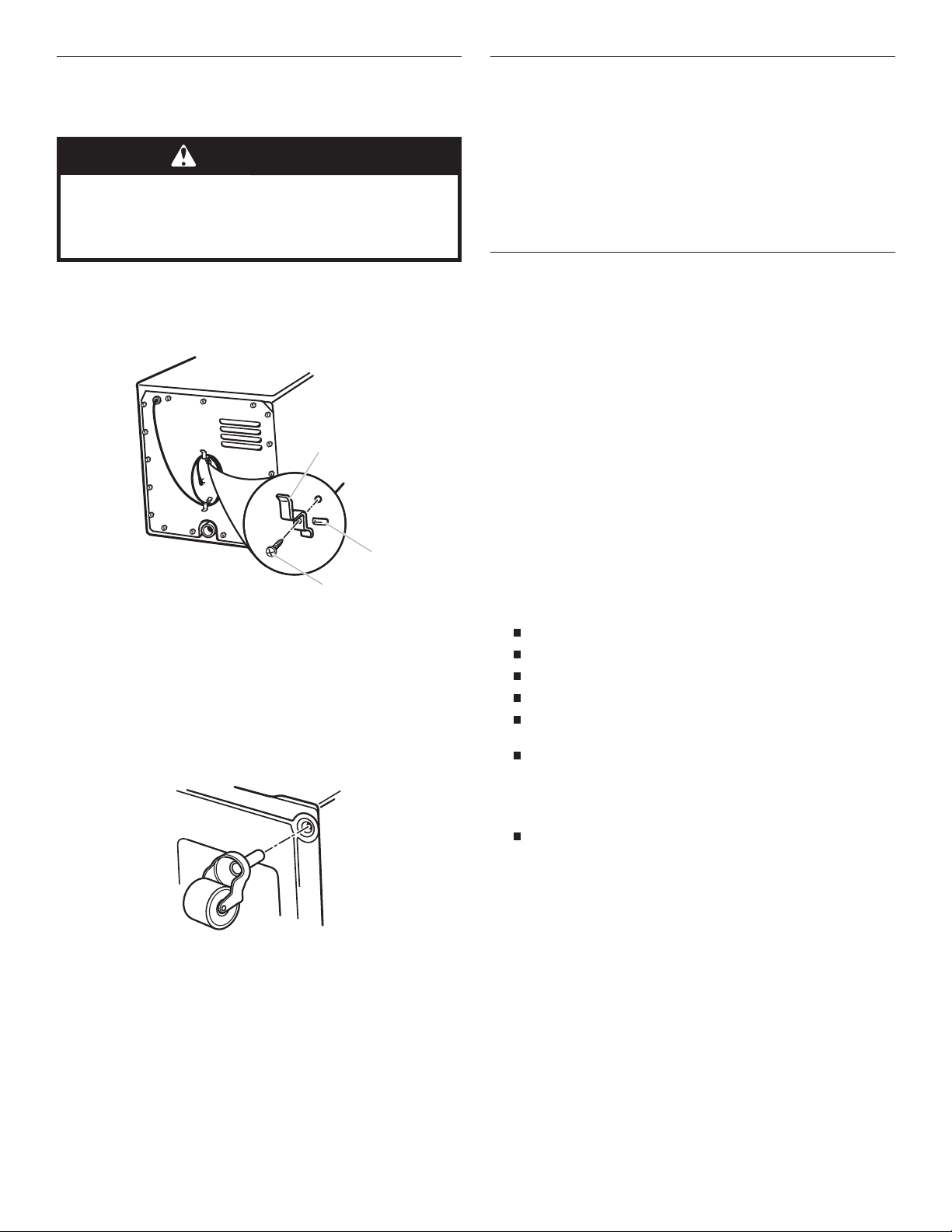
Install Cord Bracket and Casters
B
Do not move dryer into its final position until the following steps
have been performed.
WARNING
Excessive Weight Hazard
Use two or more people to move and install dryer.
Failure to do so can result in back or other injury.
Connect Vent
1. Using a 4" (102 mm) clamp, connect vent to exhaust outlet
in dryer. If connecting to existing vent, make sure the vent is
clean. The dryer vent must fit over the dryer exhaust outlet
and inside the exhaust hood. Make sure the vent is secured
to exhaust hood with a 4" (102 mm) clamp.
2. Move dryer into final position. Do not crush or kin k vent.
Make sure dryer is level.
3. (On gas models) Checkt o be sure there are no kinksin
flexible gas line.
the
Install cord bracket
1. Remove tape from the power cord and the rear panel.
2. Insert cord brackets into slotted holes in rear panel and
secure with screws provided.
A
C
A. Cord bracket
B. Slotted hole
C. Screw
NOTE: Power supply cord may be wrapped around the bracket s
for storage convenience when dryer is not in use.
Install casters
1. Lay the dryer on its side.
2. Use the carton to prevent damage to the dryer.
Complete Installation
1. Check to be sure all parts are now installed. If there is an
extra part, go back through the steps to see wh ich step was
skipped.
2. Check to be sure you have all of your tools.
3. Dispose of/r ecycle all packaging materials.
4. Check the dryer’s final location. Be sure the vent is not
crushed or kinked.
5. Check to be sure the dryer is on a level surface.
6. Plug into a grounded 3 prong outlet. Turn power on.
7. Remove the blue protective film on the console and any tape
remaining on the dryer. Remove tape from the lint screen
(located on inside back wa ll of dryer).
8. Read “Dryer Use.”
9. Wipe the dryer drum interior thoroughly wi th a damp cloth to
remove any dust.
10. To test the dryer, set the dryer on a full heat cycle (not an air
cycle) for 20 minutes and start the dryer.
If the dryer will not start, check the following:
Controls are set in a running or “On” position.
Start button has been firmly pushed.
Dryer is plugged into a grounded 3 prong outlet.
Electrical supply is connected.
House fuse is intact and tight, or circuit breaker has not
tripped.
Dryer door is closed.
11. When the dryer has been running for 5 minutes, open the
dryer door and feel for heat.
If you do not feel heat, check the following:
Controls are set on a heated cycle, not an air cycle.
NOTE: You may notice an odor when dryer is first heated.
This odor is common when the heating element is first used.
The odor willgoaway.
3. Screwcas ters into dryer base at four corners and tighten
securely.
4. Set the dryer upright. In doing so, be careful that the dryer
does not roll away from you.
NOTE: Permanent installations require 4 dryer feet. See
“Assistance or Service” section for ordering information.
8
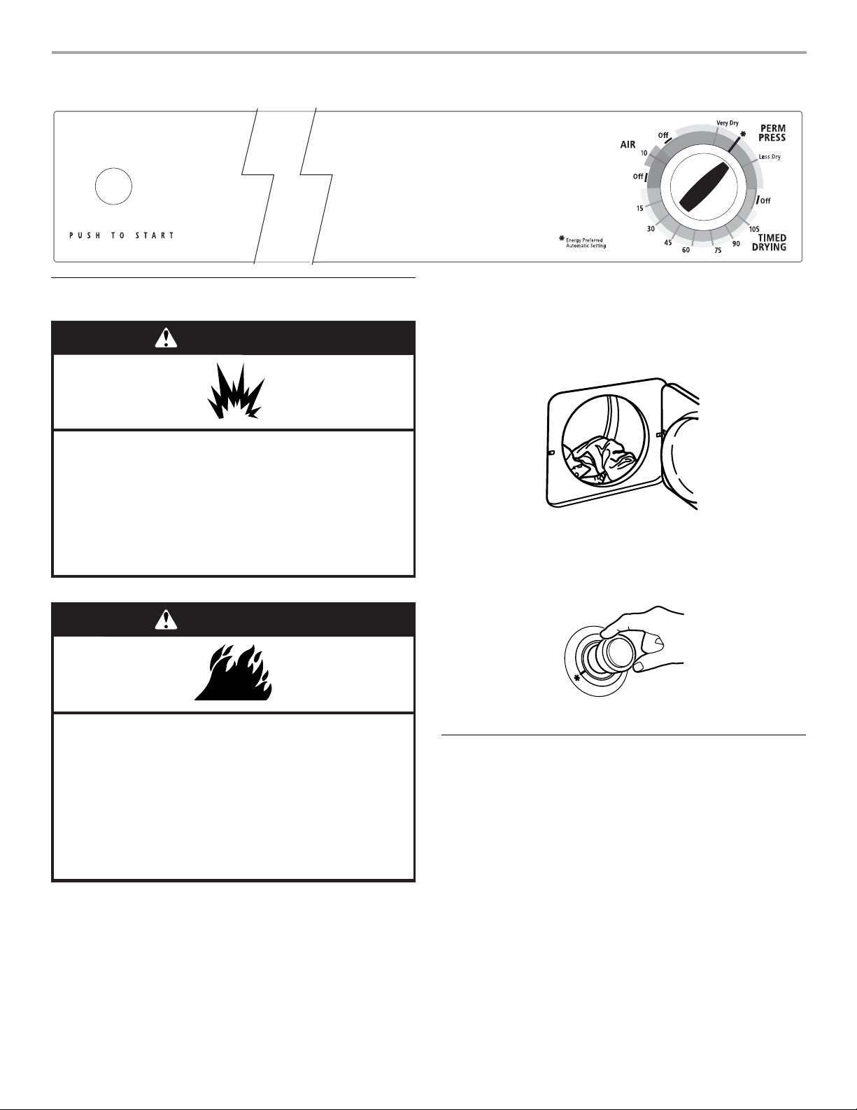
DRYER USE
Starting Your Dryer
WARNING
Explosion Hazard
Keep flammable materials and vapors, such as
gasoline, away from dryer.
Do not dry anything that has ever had anything
flammable on it (even after washing).
Failure to follow these instructions can result in death,
explosion, or fire.
Before using your dryer, wipe the dryer drum with a damp cloth to
remove dust from storing and shipping.
1. Clean the lint screen before or after each cycle. See
“Cleaning the Lint Screen.”
2. Load clothes loosely into the dryer and close the door. Do not
pack the dryer. Allow space for clothes to tumble freely.
3. Turn the Cycle Control knob to the recommended cycle for
the type of load being dried. Use the Energy Preferred
Automatic Setting (
weight loads. See “Drying, Cycle, and Temperature Tips.”
) to dry most heavyweight and medium
*
WARNING
Fire Hazard
No washer can completely remove oil.
Do not dry anything that has ever had any type of oil on
it (including cooking oils).
Items containing foam, rubber, or plastic must be dried
on a clothesline or by using an Air Cycle.
Failure to follow these instructions can result in death
or fire.
WARNING: To reduce the risk of fire, electric shock, or injury to
persons, read the IMPORTANT SAFETY INSTRUCTIONS before
operating this appliance.
4. Press the PUSH TO START button.
Stopping and Restarting
You can stop your dryer any time during a cycle.
To stop your dryer
Open the dryer door or turn the Cycle Control knob to OFF.
NOTE: The Cycle Control knob should point to an Off area when
the dryer is not in use.
To restart your dryer
1. Close the door.
2. Select a new cycle and temperature (if desired).
3. Press the PUSH TO START button.
9
 Loading...