

Whirlpool LCE4332PQ User Manual
CONSUMER SERVICES TECHNICAL
EDUCATION GROUP PRESENTS
22″ COMPACT
AUTOMATIC
WASHER
L-74
MODEL LCE4332PQ
JOB AID
Part No. 8178436

FORWARD
This Whirlpool Job Aid “22″ Compact Automatic Washer” (Part No. 8178436), provides the
technician with information on the installation, operation, and service of the 22″ Compact
Automatic Washer. It is to be used as a training Job Aid and Service Manual. For specific
information on the model being serviced, refer to the “Use and Care Guide,” or “Tech Sheet”
provided with the washer.
The Wiring Diagram and Strip Circuits used in this Job Aid are typical and should be used for
training purposes only. Always use the Wiring Diagram supplied with the product when servicing
the unit.
GOALS AND OBJECTIVES
The goal of this Job Aid is to provide detailed information that will enable the service technician to
properly diagnose malfunctions and repair the Whirlpool 22″ Compact Automatic Washer.
The objectives of this Job Aid are to:
• Understand and follow proper safety precautions.
• Successfully troubleshoot and diagnose malfunctions.
• Successfully perform necessary repairs.
• Successfully return the washer to its proper operational status.
WHIRLPOOL CORPORATION assumes no responsibility for any repairs made
on our products by anyone other than Authorized Service Technicians.
Copyright © 2004, Whirlpool Corporation, Benton Harbor, MI 49022
- ii -

TABLE OF CONTENTS
Page
GENERAL............................................................................................................................... 1-1
Safety First......................................................................................................................... 1-1
Model & Serial Number Designations ................................................................................ 1-2
Model & Serial Number Label And Tech Sheet Locations................................................. 1-3
Specifications..................................................................................................................... 1-4
Whirlpool Compact Washer Warranty ............................................................................... 1-5
INSTALLATION INFORMATION ........................................................................................... 2-1
Installation Requirements .................................................................................................. 2-1
Permanent Installation Instructions.................................................................................... 2-5
Portable Installation Instructions ...................................................................................... 2-10
PRODUCT OPERATION ........................................................................................................ 3-1
Theory Of Operation .......................................................................................................... 3-1
Washer Use ....................................................................................................................... 3-3
COMPONENT ACCESS ......................................................................................................... 4-1
Component Locations ........................................................................................................ 4-1
Removing The Pressure Switch, Water Inlet Valves, Lid Switch,
Interface And Electronic Control Boards......................................................................... 4-2
Removing The Basket ....................................................................................................... 4-6
Removing The Tub ............................................................................................................ 4-8
Removing The Brake And Gearcase Assemblies............................................................ 4-11
Removing The Capacitor And Drive Motor ...................................................................... 4-14
Removing The Brake Actuator Assembly ........................................................................ 4-16
Removing The Drain Pump ............................................................................................. 4-18
COMPONENT TESTING ........................................................................................................ 5-1
Pressure Switch ................................................................................................................. 5-1
Water Inlet Valve Solenoids............................................................................................... 5-2
Drive Motor Capacitor ........................................................................................................ 5-2
Brake Actuator ................................................................................................................... 5-3
Drive Motor ........................................................................................................................ 5-4
Drain Pump ........................................................................................................................ 5-4
DIAGNOSTICS & TROUBLESHOOTING .............................................................................. 6-1
Diagnostics ........................................................................................................................ 6-1
Time Charts .................................................................................................................... 6-2
Self Diagnostic Failure—Alarm Codes ........................................................................... 6-3
Service Routine .............................................................................................................. 6-4
Troubleshooting Guide ...................................................................................................... 6-6
WIRING DIAGRAM & STRIP CIRCUITS ............................................................................... 7-1
Wiring Diagram .................................................................................................................. 7-1
Strip Circuits ...................................................................................................................... 7-2
- iii -

— NOTES —
- iv -
GENERAL
SAFETY FIRST
Your safety and the safety of others is very important.
We have provided many important safety messages in this Job Aid and on the appliance. Always
read and obey all safety messages.
This is the safety alert symbol.
This symbol alerts you to hazards that can kill or hurt you and others.
All safety messages will follow the safety alert symbol and either the word
“DANGER” or “WARNING.” These words mean:
You can be killed or seriously injured if you don’t
DANGER
WARNING
All safety messages will tell you what the potential hazard is, tell you how to reduce the chance
of injury, and tell you what can happen if the instructions are not followed.
immediately follow instructions.
You can be killed or seriously injured if you don’t
follow instructions.
1-1

MODEL & SERIAL NUMBER DESIGNATIONS
MODEL NUMBER
MODEL NUMBER
Product Group
C = Laundry, Commercial
L = Laundry, Domestic
G = Laundry, Gold
Product Identification
A = Commercial A/W
B = Large Capacity A/W, 24" -U.S.
C = 22" Compact A/W
D = Electric Dryer, 120 volt
E = Electric Dryer, 240 volt
G = Gas Dryer
H = Electric Dryer, (Brazilian)
L = Large Capacity A/W, 27" U.S.
K = Kit
M = Reg. Capacity A/W - Mexico
P = 24" Compact A/W
S = Stack Commercial Dryer or
Super Capacity 27" A/W
T = Thin Twin
X = 96 Ex. Large Capacity A/W 27"
Z = 5KG A/W 22" - Brazil
Feature Code/Variation Lines
E = Electronic or N = No Match
Electric Thin Twin G = Gas Thin Twin
P = Pushbutton C = Clean Touch
R = Rotary L = Special
T = Circuit City W = Web
S = Water Saver V = Variation Line
Q = Rotary Quiet
Cycles - Domestic (1 - 9)
A/W (1 - 6) = Washer Speed Combinations
Washer (1 - 8) = Wash/Spin Combinations
Washer (1 - 5) = Water Levels
Year of Introduction
P = 2004
Color Code
W = White, N = Almond,
Q = White on White, Z = Almond on Almond
Engineering Change (numeric)
LCE4332PQ0
SERIAL NUMBER
SERIAL NUMBER
DIVISION RESPONSIBILITY
C = Clyde, OH
R = Multibras Rio Claro, Brazil
YEAR OF PRODUCTION
R = 2004
WEEK OF PRODUCTION
01 = 1st Week
PRODUCT SEQUENCE NUMBER
CR R 01 00102
1-2
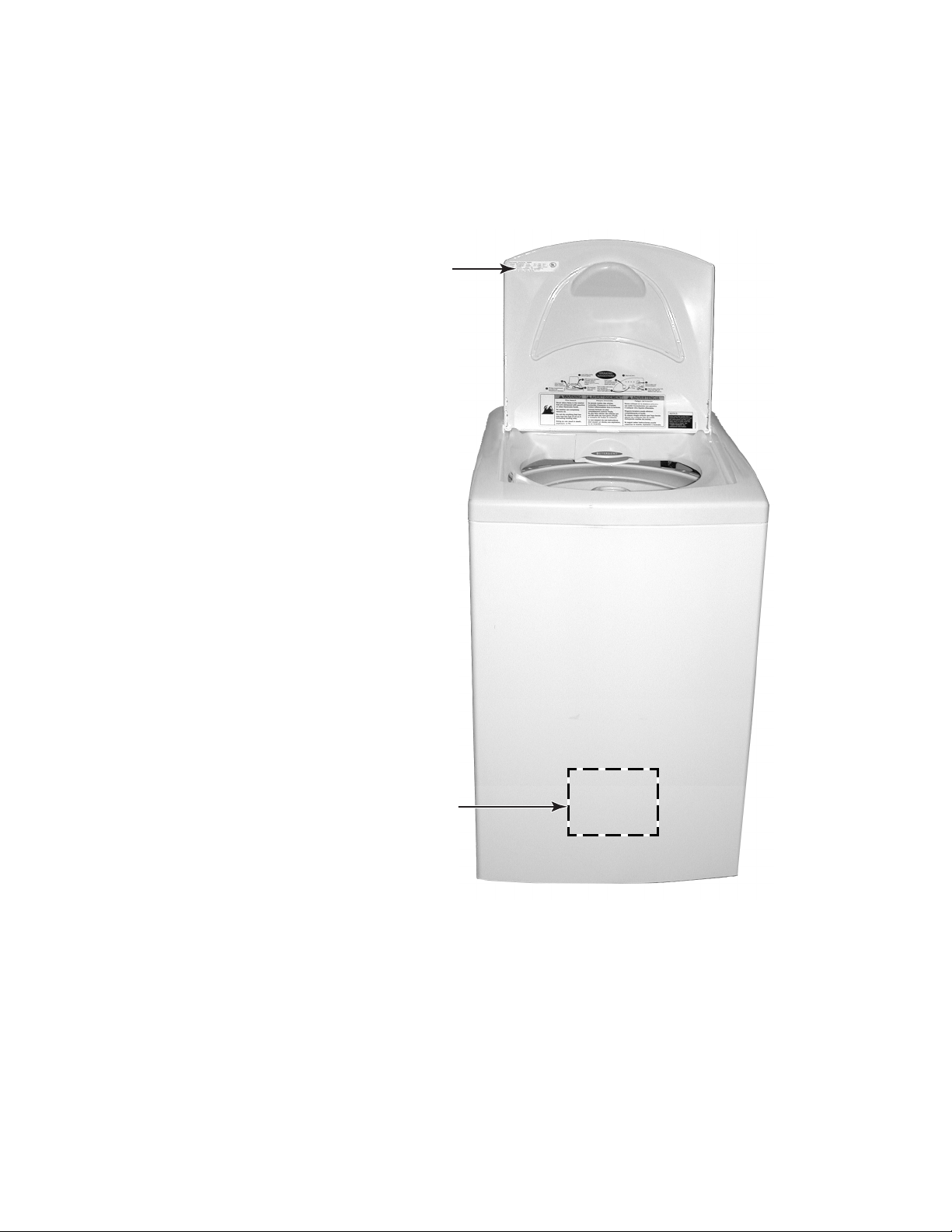
MODEL & SERIAL NUMBER LABEL
AND TECH SHEET LOCATIONS
The Model/Serial Number label and Tech Sheet locations are shown below.
Model & Serial
Number Label Location
Tech Sheet Location
(Behind Front Of Cabinet)
1-3

SPECIFICATIONS
WASHER MODEL LCE4332PQ0
WASHING SYSTEM
Washing System Agitator
Agitator Type Single Action
Basket Spinning (High) 750 rpm
Dispenser Yes - 1 drawer
Strokes Per Minute
Heavy Duty (Max) 64 spm
Normal (Max) 68 spm
Quick Wash (Max) 64 spm
Delicate (Max) 35 spm
ELECTRICAL
Nominal Voltage 120 VAC
Voltage Range 100 - 130 VAC
Frequency 60 Hz
Current (Rated) 5 amps
Motor
Power 1/4 HP
Rotation 1625 rpm
Current (Rated) 3 amps
Type PSC - Bi-directional
Drain Pump
Power 36 Watts
Current 0.8 amps
Flow 24 liters/minute
Capacitance
Circuit Breaker 15 amps (recommended)
HYDRAULIC
Max. Water Consumption (All Cycles)
High 33 gal./124 l
Medium 17 gal./64 l
Water Pressure
Maximum 690 kPa/100 psi
Minimum 34.5 kPa/5 psi
Water Level
High Just below balance ring
Medium 5 rows below balance ring
DIMENSIONS
Net Weight 86.4 lbs. (39.2 kg)
Height 38.2 in. (970 mm)
Width 22.2 in. (565 mm)
Depth 24.6 in. (625 mm)
Height W/Lid Open 51.1 in. (1300 mm)
Weight W/Package 94.8 lbs. (43 kg)
Height W/Package 41.7 in. (1060 mm)
Depth W/Package 26.6 in. (675 mm)
Width W/Package 25 in. (635 mm)
45 µF
1-4

WHIRLPOOL COMPACT WASHER WARRANTY
ONE-YEAR FULL WARRANTY
For one year from the date of purchase, when this washer is operated and maintained according to
instructions attached to or furnished with the product, Whirlpool Corporation will pay for FSP replacement
parts and repair labor costs to correct defects in materials or workmanship. Service must be provided by
a Whirlpool designated service company.
SECOND THROUGH FIFTH YEAR LIMITED WARRANTY
ON TOP, LID, AND GEARCASE ASSEMBLY
For the second through the fifth year from the date of purchase when this washer is operated and
maintained according to instructions attached to or furnished with the product, Whirlpool Corporation will
pay for FSP replacement parts for any top and lid rust and any part of the gearcase assembly, if defective
in materials or workmanship.
SECOND THROUGH TENTH YEAR LIMITED WARRANTY ON OUTER TUB
For the second through the tenth year from the date of purchase when this washer is operated and
maintained according to instructions attached to or furnished with the product, Whirlpool Corporation will
pay for FSP replacement parts for the outer tub should it crack or fail to contain water, if defective in
materials or workmanship.
Whirlpool Corporation will not pay for:
1. Service calls to correct the installation of your washer, to instruct you how to use your washer, or to
replace house fuses or correct house wiring or plumbing.
2. Repairs when your washer is used in other than normal, single-family household use.
3. Damage resulting from accident, alteration, misuse, abuse, fire, flood, acts of God, improper installation,
not in accordance with local electrical and plumbing codes, or use of products not approved by Whirlpool
Corporation.
4. Any labor costs during the limited warranty periods.
5. Replacement parts or repair labor costs for units operated outside the United States and Canada.
6. Pickup and delivery. This product is designed to be repaired in the home.
7. Repairs to parts or systems resulting from unauthorized modifications made to the appliance.
8. In Canada, travel or transportation expenses for customers who reside in remote areas.
WHIRLPOOL CORPORATION AND WHIRLPOOL CANADA INC.
SHALL NOT BE LIABLE FOR INCIDENTAL OR CONSEQUENTIAL DAMAGES.
Some states and provinces do not allow the exclusion or limitation of incidental or consequential damages
so this exclusion or limitation may not apply to you. This warranty gives you specific legal rights and you
may also have other rights which vary from state to state or province to province.
Outside the 50 United States and Canada, this warranty does not apply. Contact your authorized
Whirlpool dealer to determine if another warranty apples.
If you need service first see “Troubleshooting” in the “Use & Care Guide.” Additional help can be found by
checking “Assistance or Service” or call our Customer Interaction Center at 1-800-253-1301 from
anywhere in the U.S.A., or write: Whirlpool Brand Home Appliances, Customer Interaction Center, 553
Benson Road, Benton Harbor, MI 49022-2692. In Canada, call Whirlpool Canada Inc. at 1-800-807-6777.
1-5

— NOTES —
1-6
INSTALLATION INFORMATION
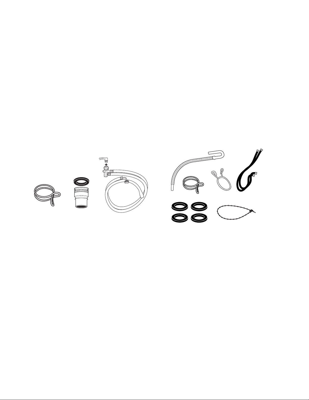
A. Drain hose
B. Silver, double-wire hose clamp
(for the botto m of the drain hose)
C. Yellow, single-w ire hose clamp
(for the top of the drain hose)
D. Water inlet hoses (2)
E. Flat water inlet hose
washers (4)
F. Beaded tie strap
A
BC
D
E
F
INSTALLATION REQUIREMENTS
TOOLS AND PARTS
Assemble the required tools and parts before
starting installation. Read and follow the instructions provided with any tools listed here.
The parts supplied are in the washer basket.
Portable Installation
Tools needed:
• Pliers that open to 1-9/16″ (3.95 cm)
• Utility knife
• Flashlight (optional)
Parts supplied:
Permanent Installation
Tools needed:
• Pliers that open to 1-9/16″ (3.95 cm)
• Flashlight (optional)
• Adjustable or open end wrench 9/16″
(14 mm)
• Level
• Wood block
• Utility knife
• Measuring tape
Parts supplied:
A
A. Silver, double-wir e hose clamp (for the bottom of the
drain hose)
B. Faucet adapter
C. Fill-and-drain hose
B
C
NOTE: To change a permanent installation to
a portable installation, kit #285768 is required.
NOTE: To change a portable installation to a
permanent installation, kit #4396746 is required.
2-1
Alternate Parts
Your installation may require additional parts.
For ordering information, please refer to the
“Assistance or Service” section of the “Use &
Care Guide.”
If You Have: You Will Need to Buy:
Laundry tub or Sump pump system (if not
standpipe taller already available)
than 72″ (183 cm)
1″ (2.5 cm) diameter 2″ (5 cm) diameter to 1″
standpipe diameter standpipe adapter
#3363920
Overhead sewer Standard 20 gal. (76 L) 39″
(99 cm) tall drain tub or
utility sink, sump pump and
connectors (available from
local plumbing suppliers)
Floor drain Siphon break, #285320;
additional drain hose,
#3357090 and connector kit,
#285442
Water faucets 2 longer water fill hoses:
beyond reach of 6 ft (1.8 m) #76314,
fill hoses 10 ft (3.0 m) #350008
Drain hose too Drain hose, #388423 and
short hose kit, #285442
Drain hose that is Hose kit, #285442
too long
Lint clogged drain Drain protector, #367031
• Hot and cold water faucets located within
3-1/2 ft (1.1 m) of the hot and cold water fill
valves, and water pressure of 5-100 psi
(34.5-690 kPa).
• A level floor with a maximum slope of 3/4″
(2.0 cm) under entire washer. Installing the
washer on carpeting is not recommended.
• A sturdy floor to support the washer weight
(washer, water and load) of 260 lbs (118 kgs).
Do not store or operate your washer in temperatures at or below 32°F (0°C). Some water
can remain in the washer and can cause damage in low temperatures. See “Washer Care”
in the “Use & Care Guide” for winterizing information.
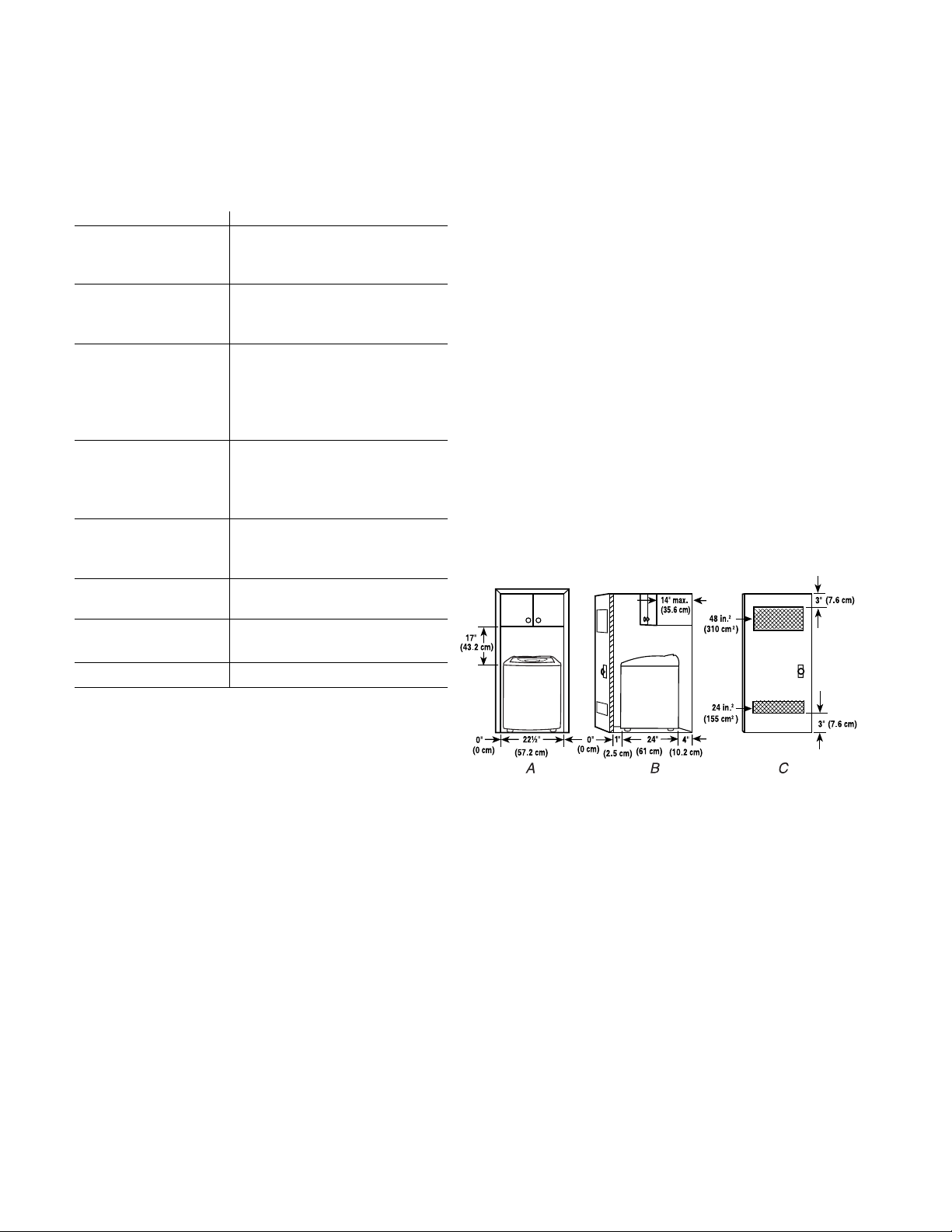
Recessed area or closet installation
The dimensions shown are for the recommended spacing allowed, except the closet
door ventilation openings. The dimensions
shown for the closet door ventilation openings
are the minimum required.
LOCATION REQUIREMENTS
Selecting the proper location for your washer
improves performance and minimizes noise
and possible washer “walk.”
Your washer can be installed in a basement,
laundry room, closet, or recessed area (see
“Drain System”).
IMPORTANT: Do not install or store the washer
where it will be exposed to the weather.
Proper installation is your responsibility.
You Will Need:
• A water heater set to deliver 120°F (49°C)
water to the washer.
• A grounded electrical outlet located within
5 ft (1.5 m) of where the power cord is
attached to the back of the washer (see
“Electrical Requirements”).
A. Front view
B. Side view
C. Closet door with vents
• Additional spacing should be considered for
ease of installation and servicing.
• Additional clearances may be required for
wall, door and floor moldings.
• Additional spacing of 1″ (2.5 cm) on all sides
of the washer is recommended to reduce
noise transfer.
• If a closet door is installed, the minimum air
openings in the top and bottom of the door
are required. Louvered doors with air openings in the top and bottom are acceptable.
• Companion appliance spacing should also
be considered.
2-2
ELECTRICAL REQUIREMENTS
t
WARNING
Electrical Shock Hazard
• If codes permit and a separate ground wire
is used, it is recommended that a qualified
electrician determine that the ground path is
adequate.
• Do not ground to a gas pipe.
• Check with a qualified electrician if you are
not sure the washer is properly grounded.
• Do not have a fuse in the neutral or ground
circuit.
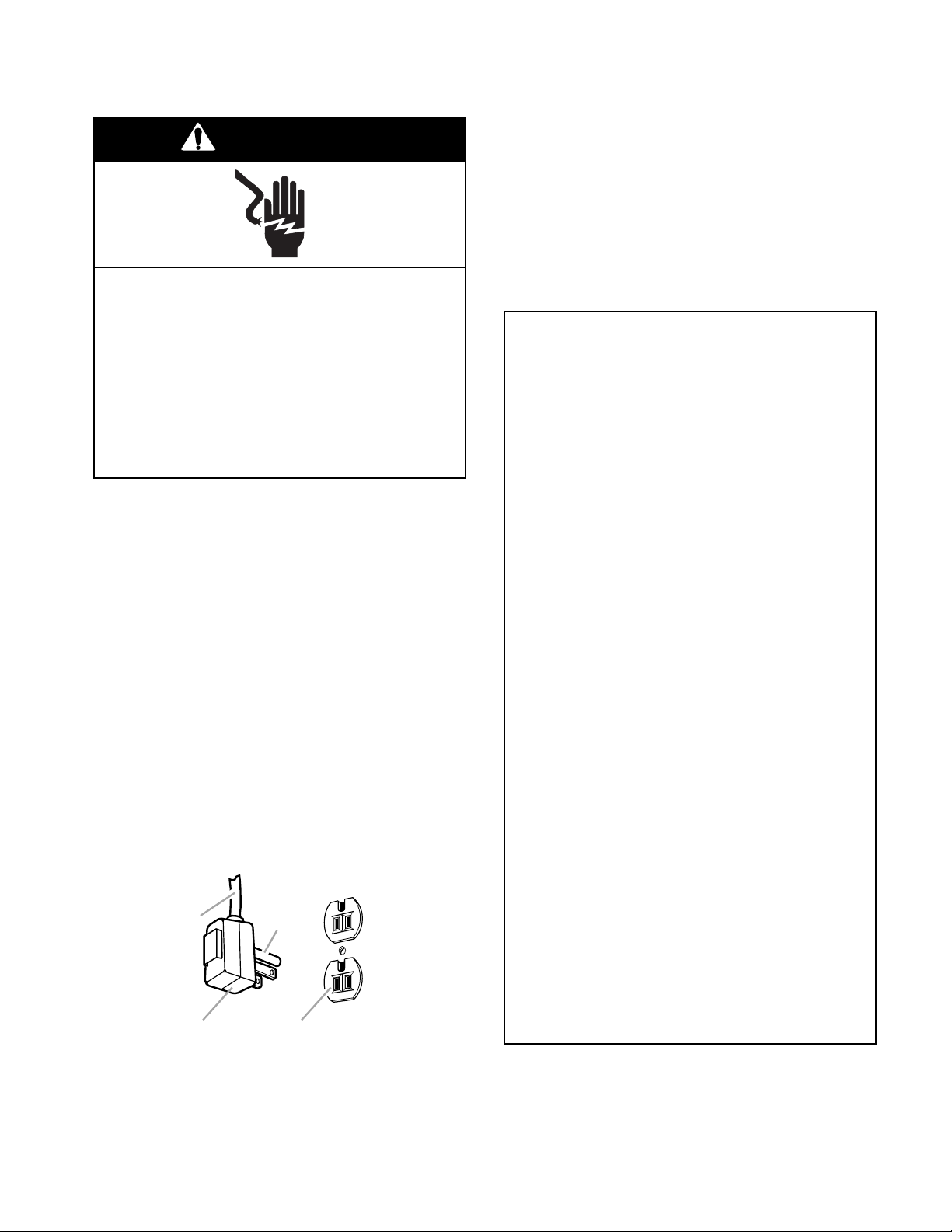
Plug into a grounded 3 prong outlet.
Do not remove ground prong.
Do not use an adapter.
Do not use an extension cord.
Failure to follow these instructions can
result in death, fire, or electrical shock.
• A 120-volt, 60-Hz., AC-only, 15- or 20-ampere, fused electrical supply is required. A
time-delay fuse, or circuit breaker, is recommended. It is recommended that a separate
circuit serving only this appliance be provided.
• This washer is equipped with a power supply
cord having a 3 prong grounding plug.
• To minimize possible shock hazard, the cord
must be plugged into a mating, 3 prong,
grounding-type outlet, grounded in accordance with local codes and ordinances. If a
mating outlet is not available, it is the personal responsibility and obligation of the
customer to have the properly grounded
outlet installed by a qualified electrician.
GROUNDING INSTRUCTIONS
For a grounded, cord-connected
washer:
This washer must be grounded. In the event
of a malfunction or breakdown, grounding
will reduce the risk of electrical shock by
providing a path of least resistance for electric current. This washer is equipped with a
cord having an equipment-grounding conductor and a grounding plug. The plug must
be plugged into an appropriate outlet that is
properly installed and grounded in accordance with all local codes and ordinances.
WARNING: Improper connection of the
equipment-grounding conductor can result
in a risk of electric shock. Check with a
qualified electrician or serviceman if you are
in doubt as to whether the appliance is
properly grounded.
Do not modify the plug provided with the
appliance. If it will not fit the outlet, have a
proper outlet installed by a qualified electrician.
B
A
A. 3 p rong grounding plug
B.
Power supply cord
C. Ground prong
D.
3 prong grounding-type outle
C
D
For a permanently connected washer:
This washer must be connected to a grounded
metal, permanent wiring system, or an equipment-grounding conductor must be run with
the circuit conductors and connected to the
equipment-grounding terminal or lead on the
appliance.
2-3
REMOVE SHIPPING MATERIAL
WARNING
Excessive Weight Hazard
Use two or more people to move and
install washer.
Failure to do so can result in back or
other injury.
Before you install your washer, remove all
shipping material.
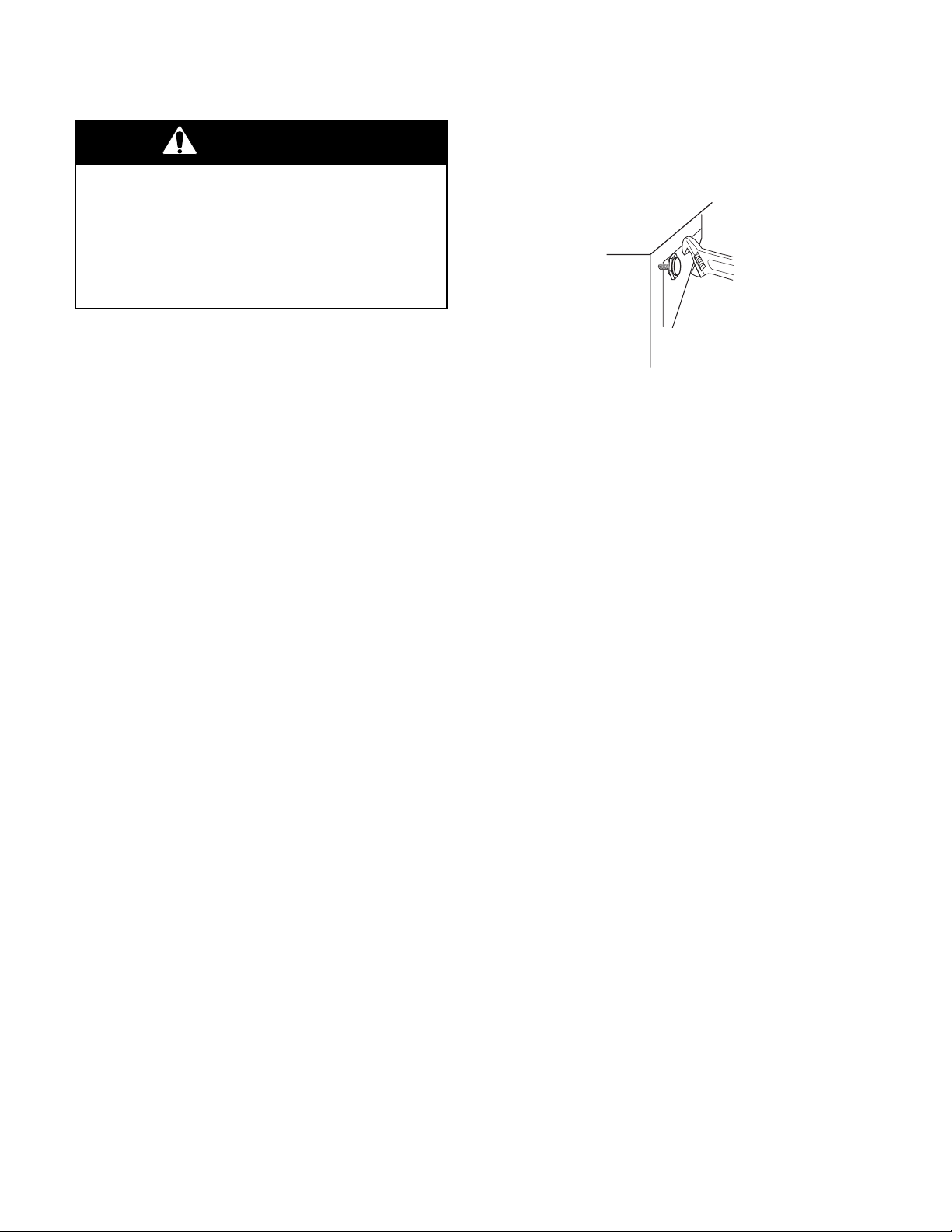
4. For permanently installed compact
washers only, use an adjustable wrench
to turn the washer legs out approximately
3/4″ (2.0 cm). This is the recommended
setting. Later adjustment may be needed.
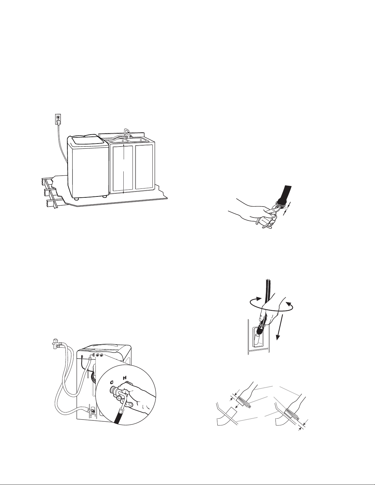
1. To protect the floor, place two corner posts
from the shipping material on the floor in
back of the washer.
2. Firmly grasp the body of the washer and
gently lay it on the corner posts.
3. Remove plastic foam packaging from under washer.
5. Stand the washer up.
6. Remove the tape from the washer lid.
Open the washer lid and remove the foam
shipping piece, parts bag, and hoses from
the washer basket. Close the lid.
NOTE: If you are using a permanent installation, proceed to page 2-5. If you are using a
portable installation, proceed to page 2-10.
2-4
39"
(99 cm)
AB
PERMANENT INSTALLATION INSTRUCTIONS
WARNING
Excessive Weight Hazard
Use two or more people to move and
install washer.
Failure to do so can result in back or
other injury.
BEFORE YOU START
• To prevent floor damage, set the washer
onto cardboard before moving across floor.
• Move the washer to within approximately 3 ft
(90 cm) of the final location.
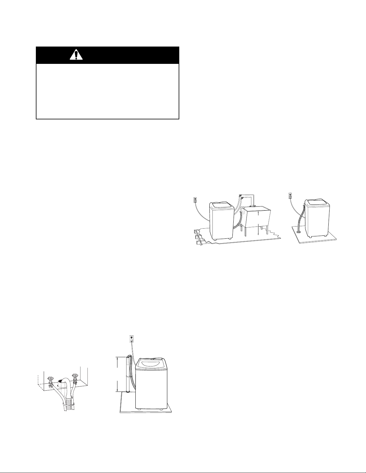
DRAIN SYSTEM
The washer can be installed using the standpipe
drain system (floor or wall), the laundry tub
drain system, or the floor drain system. Select
the drain hose installation method you need.
Laundry tub drain system (view A)
The laundry tub requires a minimum carryaway capacity of 13 gal. (49.2 L) per minute.
The top of the laundry tub must be at least 39″
(99 cm) above the floor and no higher than 72″
(183 cm) from the bottom of the washer.
Floor drain system (view B)
The floor drain system requires a siphon break
that may be purchased separately (see “Alternate Parts” on page 2-2).
The siphon break must be a minimum of 28″
(71 cm) from the bottom of the washer. Additional hoses might be needed.
The minimum carry-away capacity can be no
less than 13 gallon (49.2 L) per minute.
Standpipe drain system - wall or floor
(views A & B)
The standpipe drain requires a minimum diameter standpipe of 2″ (5 cm). The minimum
carry-away capacity can be no less than
13 gallons (49.2 L) per minute. A 2″ (5 cm)
diameter to 1″ (2.5 cm) diameter standpipe
adapter kit is available (see “Alternate Parts”
on page 2-2).
The top of the standpipe must be at least
39″ (99 cm) high and no higher than 72″ (183 cm)
from the bottom of the washer.
39"
(99 cm)
CONNECT DRAIN HOSE
Proper connection of the drain hose will protect
your floors from damage due to water leakage.
To prevent the drain hose from coming off or
leaking, it must be installed per the following
instructions.
IMPORTANT: To ensure proper installation,
this procedure must be followed exactly.
1. Check the drain hose to see that it is the
proper length.
2. Wet the inside of the straight end of the
drain hose with tap water. IMPORTANT:
Do not use any lubricant other than water.
AB
2-5
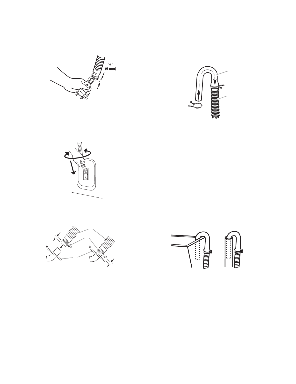
3. Squeeze the ears of the silver, doublewire clamp with pliers to open it. Place the
clamp over the straight end of the drain
hose 1/4″ (6 mm) from the end.
4. Open the clamp and twist the hose back
and forth while pushing down onto the
drain connector at the bottom of the washer.
Continue until the hose contacts the cabinet.
For standpipe or laundry tub drain systems
1. Open the yellow, single-wire clamp with
pliers, and slide it over the hooked end of
the drain hose to secure the rubber and
corrugated sections together.
A
B
A. Hooked end
B. Drain hose
2. Place the hooked end of drain hose into
the laundry tub, or standpipe. Rotate the
hook to eliminate kinks.
To prevent drain water from going back into the
washer:
5. Place the clamp over the area marked
“CLAMP,” and release the clamp.
1/4"
(6 mm)
C
A. Drain hose
B. Clamp
C. Cabinet
A
B
1/4"
(6 mm)
• Do not straighten the hooked end of drain
hose.
• Do not force excess drain hose into the
standpipe. The hose should be secure, but
loose enough to provide a gap for air.
• Do not lay excess drain hose in the bottom of
the laundry tub.
• For floor drain installation, see kit number
required under “Alternate Parts” on page
2-2.
2-6
CONNECT THE INLET HOSES
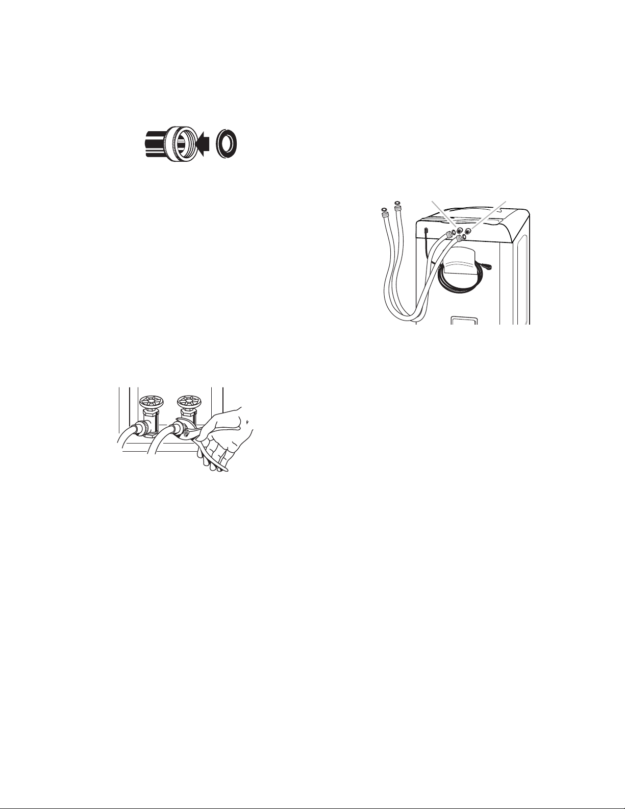
1. Insert the new flat washers (supplied) into
each end of the inlet hoses. Firmly seat the
washers in the couplings.
A B
A. Coupling
B. Washer
7. Attach the hose with the red coupling to
the HOT (right) inlet valve. Attaching the
red coupling first makes it easier to tighten
connection with pliers. Screw the coupling
on by hand until it is seated on the washer.
Using pliers, tighten the couplings with an
additional two-thirds turn. NOTE: Do not
overtighten the couplings, or damage to
the valves may result.
A
B
2. Make sure the washer basket is empty.
3. Attach the hose with the red coupling to
the hot water faucet. Screw the coupling
on by hand until it is seated on the washer.
4. Attach the hose with the blue coupling to
the cold water faucet. Screw the coupling
on by hand until it is seated on the washer.
5. Using pliers, tighten the couplings an additional two-thirds turn. NOTE: Do not
overtighten the couplings, or damage to
the valves may result.
6. Run water through both faucets and inlet
hoses, into a bucket or laundry tub, to get
rid of particles in the water lines that might
clog the inlet valve screens.
C
H
A. Cold water inlet valve (blue)
B. Hot water inlet valve (red)
8. Attach the hose with the blue coupling to
the COLD water (left) inlet valve. Screw
the coupling on by hand until it is seated on
the washer. Using pliers, tighten the couplings with an additional two-thirds turn.
NOTE: Do not overtighten the couplings,
or damage to the valves may result.
2-7
9. Turn on the water faucets and check for
leaks. A small amount of water might enter
the washer. You will drain this later.
NOTE: Replace inlet hoses after 5 years of use
to reduce the risk of hose failure. Record the
hose installation or replacement dates for future reference.
• If you connect only one water hose, you must
cap off the remaining water inlet port.
• Periodically inspect and replace the hoses if
bulges, kinks, cuts, wear, or leaks are found.
SECURE DRAIN HOSE
1. Drape the power cord over the console.
2. Move the washer to its final location and
remove any cardboard used to move
washer.
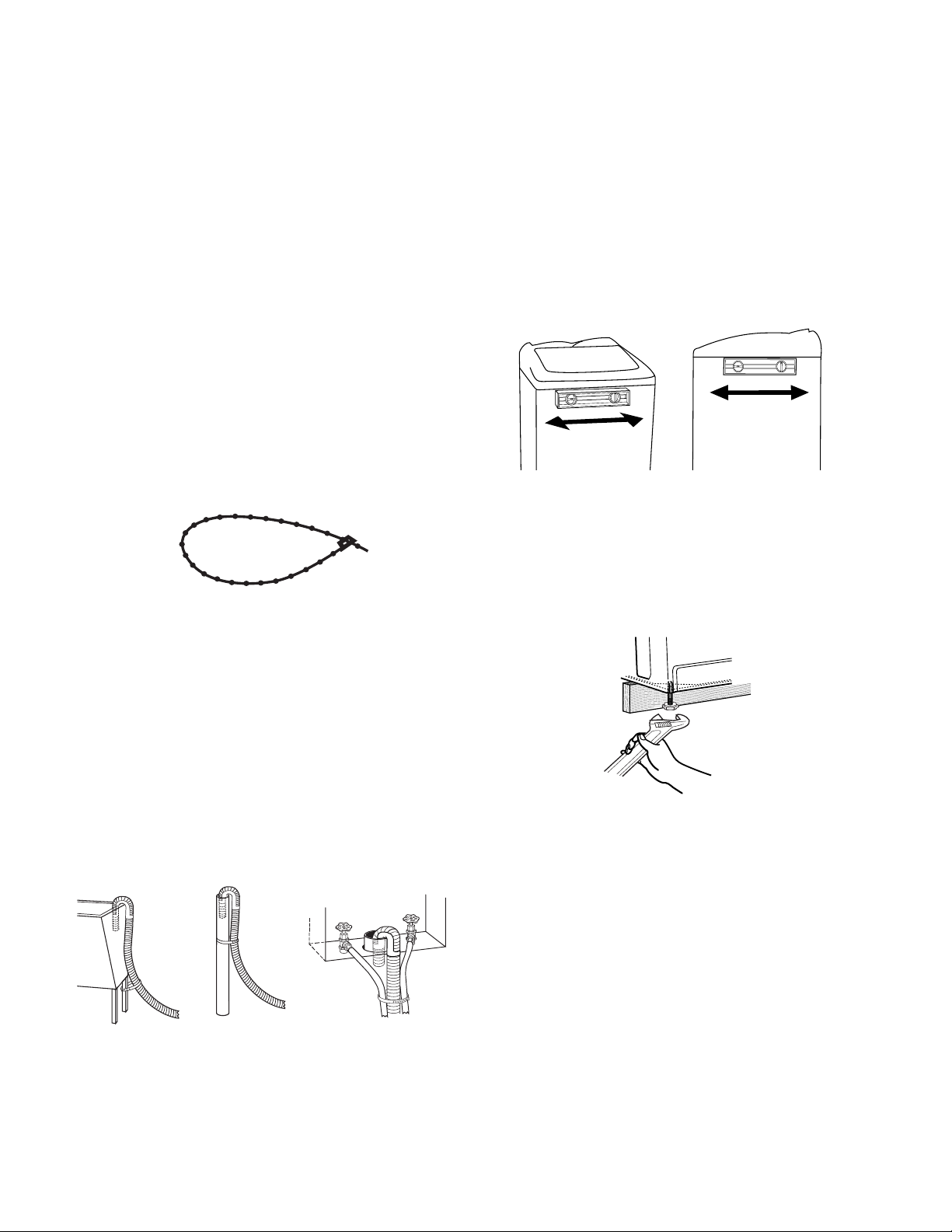
LEVEL THE WASHER
Properly leveling the washer will help prevent
excessive noise and vibration. To level the
washer:
1. Move the washer to its final location.
2. Check to see if the washer is level. Check
from side-to-side and from front-to-back
by lining up the level with the top edge of
the washer cabinet where it meets the
washer top.
3. Locate the beaded tie strap (supplied).
Beaded Tie Strap
4. Wrap the drain hose to the laundry tub leg
or standpipe with the tie strap (see illustrations A and B).
If the washer faucets and the drain
standpipe are recessed, place the hooked
end of the drain hose in the standpipe (see
illustration C). Tightly wrap the tie strap
around the water inlet hoses and the drain
hose.
Do not force excess drain hose back into the
rear of the washer.
3. If the washer is not level, prop up the front
of the washer with the wood block and
adjust the feet up or down as necessary. If
the washer is against a wall, move the
washer out slightly before tipping back.
Repeat this step until washer is level.
A
B C
2-8

COMPLETE INSTALLATION
1. Check the electrical requirements on page
2-3, and make sure that you have the
correct electrical supply and the recommended grounding method.
2. Check to be sure that all the parts are now
installed. If there is an extra part, go back
through the steps to see which step was
skipped.
3. Check to be sure you have all of your tools.
4. Dispose or recycle all packaging materials. Keep the expanded foam plug for use
if the washer should be transported.
5. Check to be sure the water faucets are on.
6. Check for leaks around faucets and inlet
hoses.
WARNING
Electrical Shock Hazard
Plug into a grounded 3 prong outlet.
Do not remove ground prong.
Do not use an adapter.
Do not use an extension cord.
Failure to follow these instructions can
result in death, fire, or electrical shock.
7. Plug into a grounded 3 prong outlet.
8. Read the “Washer Use.”
9. To test the washer:
a) Measure and add 1/2 the normal rec-
ommended amount of detergent to the
washer.
b) Close the lid.
c) Select any cycle, and then press the
START/OFF keypad.
d) Allow the washer to complete one
whole cycle.
2-9
PORTABLE INSTALLATION INSTRUCTIONS
DRAIN SYSTEM
The washer must drain into a sink or laundry
tub with a carry-away capacity of 7 gallons
(26.6 L) per minute. The top of the tub must be
at least 27″ (68.6 cm) above floor, and no
higher than 48″ (121.9 cm) from the bottom of
the washer.
27"
(68.6 cm)
CONNECT FILL-AND-DRAIN HOSE
Connect Drain Hose
To prevent the fill-and-drain hose from leaking,
it must be installed per the following instructions.
IMPORTANT: To ensure proper installation,
this procedure must be followed exactly.
1. Wet the inside end of the fill-and-drain
hose with tap water. IMPORTANT: Do not
use any lubricant other than water.
2. Squeeze the ears of the silver, doublewire clamp with pliers to open the clamp.
3. Place the clamp over the straight end of
the drain hose so it is 1/4″ (6 mm) from the
end.
(6 mm)
1/4"
Proper connection of the fill-and-drain hose will
protect your floors from damage due to water
leakage. To connect the hoses:
Connect Fill Hose
Attach the fill-and-drain hose to the cold water
(left) inlet valve. Tighten coupling by hand. Use
pliers to make an additional two-thirds turn.
NOTE: Do not overtighten the couplings, or
damage to the valves may result.
The hot water (right) inlet valve is capped.
Leave this valve capped.
4. Open the clamp. Twist the hose back and
forth while pushing down onto drain connector at the bottom of the washer. Continue until hose contacts the cabinet.
5. Place the clamp over the area marked
“CLAMP,” and release it.
1/4"
(6 mm)
A
B
1/4"
C
(6 mm)
2-10
A. Drain hose
B. Clamp
C. Cabinet
 Loading...