

Page 1
KR-28
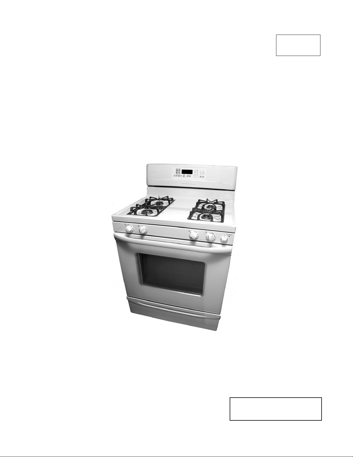
WHIRLPOOL GAS RANGE
DIRECT SPARK
IGNITION SYSTEM
JOB AID
Part No. 8177893
Page 2

FORWARD
This Job Aid, “Whirlpool Gas Range Direct Spark Ignition System,” (Part No. 8177893), provides
the technician with information on the operation and service of the Direct Spark Ignition System.
It is to be used as a training Job Aid and Service Manual.
The Wiring Diagrams used in this Job Aid are typical and should be used for training purposes
only. Always use the Wiring Diagrams supplied with the product when servicing the unit.
GOALS AND OBJECTIVES
The goal of this Job Aid is to provide detailed information that will enable the service technician to
properly diagnose malfunctions and repair the Direct Spark Ignition System.
The objectives of this Job Aid are to:
• Understand and follow proper safety precautions.
• Successfully troubleshoot and diagnose malfunctions.
• Successfully perform necessary repairs.
• Successfully return the Direct Spark Ignition System to the proper operational status.
WHIRLPOOL CORPORATION assumes no responsibility for any repair
made on our products by anyone other than Authorized Factory Service
Technicians.
Copyright 2000, Whirlpool Corporation, Benton Harbor, MI 49022
- ii -
Page 3

Table of Contents
PAGE
SECTION 1 ................................................................................................................................ 1
THEORY OF OPERATION ........................................................................................................ 1
Introduction ........................................................................................................................... 1
Gas Distribution Valve ..........................................................................................................2
Manual Oven Shutoff Valve .............................................................................................. 3
Bake & Broil Solenoid-Activated Ports.............................................................................. 4
L.P. Gas Conversion.............................................................................................................5
Direct Spark Ignition Control ................................................................................................. 7
Electronic Spark Ignition .......................................................................................................8
Cooktop Burner Operation ................................................................................................ 8
Oven Burner Operation..................................................................................................... 9
SECTION 2 .............................................................................................................................. 11
COMPONENT ACCESS .......................................................................................................... 11
Removing The Direct Spark Ignition Control ...................................................................... 11
Removing The Gas Distribution Valve ................................................................................ 12
SECTION 3 .............................................................................................................................. 13
COMPONENT TESTING ......................................................................................................... 13
Direct Spark Ignition Control ............................................................................................... 13
Gas Distribution Valve ........................................................................................................ 17
SECTION 4 .............................................................................................................................. 19
WIRING DIAGRAM & STRIP CIRCUITS ................................................................................. 19
Wiring Diagram ................................................................................................................... 19
Strip Circuits ....................................................................................................................... 20
SECTION 5 .............................................................................................................................. 23
TECH TIPS .............................................................................................................................. 23
Diagnostic Flow Charts ....................................................................................................... 23
- iii -
Page 4

IMPORTANT SAFETY INFORMATION
Your safety and the safety of others is very important.
Important safety messages have been provided in this Job Aid. Always read and obey all
safety messages.
This is the safety alert symbol.
This symbol alerts you to hazards that can kill or hurt you and others.
All safety messages will be preceded by the safety alert symbol and the word
“WARNING.”
All safety messages will identify the hazard, tell you how to reduce the chance of injury, and tell
you what can happen if the instructions are not followed.
GENERAL INFORMATION
IMPORTANT MODEL & SERIAL
NUMBER INFORMATION
The Direct Spark Ignition System is used on
Whirlpool gas ranges produced, beginning
January 3, 2000, Serial Code RK02. The Model
number of these units will be a “-5” version of
the current G-line gas range.
Example: SF365PEGQ5
This Direct Spark Ignition System will only be
available on self-cleaning gas ranges.
ELECTRICAL REQUIREMENTS
The supply voltage is critical for proper operation of the Direct Spark Ignition (DSI) System.
The requirements are 102 to 132 VAC with the
proper polarity and ground. If the electrical supply is less than 102 VAC, sparking will not be
reliable. If the system is over 132 VAC, permanent damage to the DSI can occur.
Proper polarity must also be supplied. If the
supply polarity is reversed, the DSI control will
not be able to detect the presence of a flame.
Reverse polarity will not affect the cooktop operation, but the Bake and Broil burners will fail
to remain lit.
A proper ground is also required. The DSI control generates a significant amount of electrical noise. This noise is minimized by clamping the noise to ground. If a proper ground is
not connected, the ERC may periodically display “PF,” which means that a reset has occurred in the ERC.
GAS REQUIREMENTS
Gas supply pressure should be a minimum of
7˝ water column pressure for natural gas, and
11˝ water column pressure for L.P. gas. However, the gas distribution valve should maintain 4˝ water column pressure for natural gas,
and 10˝ water column pressure for L.P. gas.
NOTE TO TECHNICIAN: Improper polarity will cause the direct spark ignition
system to malfunction. Always check for
proper polarity at the wall outlet before
replacing parts.
- iv -
Page 5
SECTION 1SECTION 1
SECTION 1
SECTION 1SECTION 1
THEORY OF OPERATION
INTRODUCTION
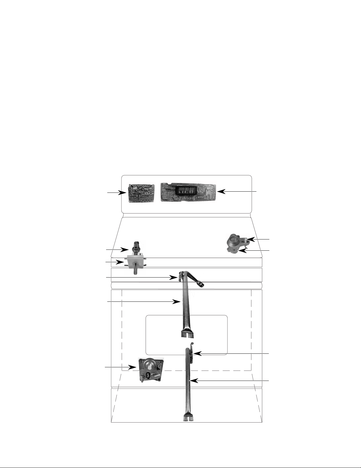
The Direct Spark Ignition System contains a
Gas Distribution Valve and a Direct Spark Ignition (DSI) Control that interfaces with the
Electronic Oven Control, and spark electrodes.
This provides the direct spark ignition and gas
distribution for Whirlpool self-cleaning gas freestanding ranges.
A proper ground and the correct polarity is necessary for the DSI control to sense the pres-
Direct Spark
Ignition Control
Gas Valve /
ence of a flame. If the polarity is reversed, or
in some cases if there is a poor ground, the
control will appear to operate normally. However, after an oven burner ignites, the spark
will continue to occur at the burner, and the
valve will then shut off after 4 seconds. This is
because the DSI control does not recognize
the presence of a flame when one is present
(see “Monitoring System,” on page 9).
Gas Distribution Valve
Ignitor &
Cooktop Burner
Ignition Switch
Broil Burner Ignitor
Broil Burner
Gas Distribution Valve
Bake Burner Ignitor
Bake Burner
- 1 -
Page 6
GAS DISTRIBUTION VALVE
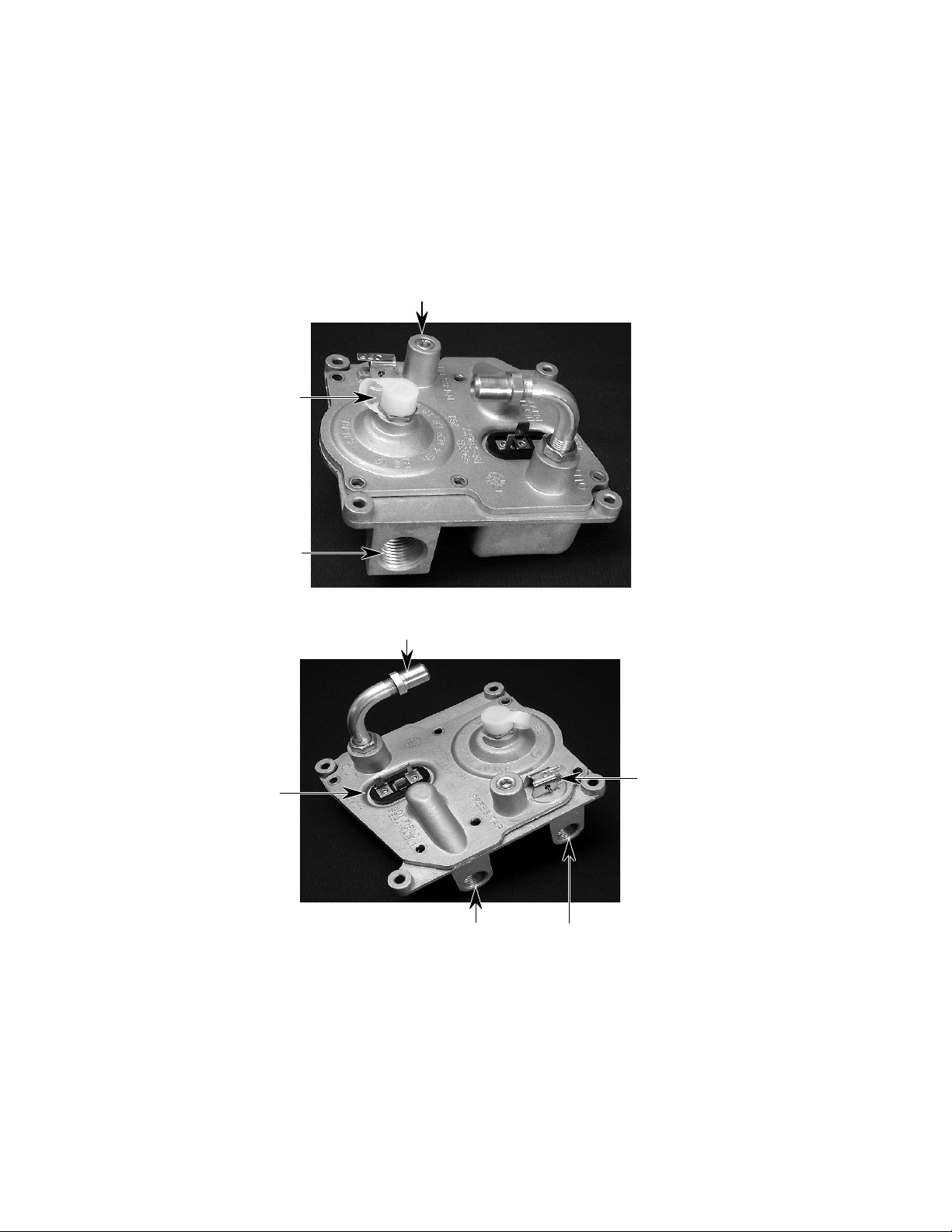
The gas distribution valve can be converted to
L.P. gas, when necessary. It regulates the distribution of gas to the cooktop and both oven
burners. The gas distribution valve is non-serviceable.
Pressure Tap
(1/8˝ - 27 N.P.T.)
L.P. Conversion Cap
Gas Inlet (1/2˝
Female Threads)
The gas distribution valve is made up of the
following features:
• Natural & L.P. gas regulator
• Manual oven shutoff valve
• Bake & broil solenoids
• Pressure tap - To measure gas outlet
pressure
Electrical
Terminals
To Bake Burner
To Broil Burner
Gas Distribution Valve
Manual Oven
Shutoff Valve
To Cooktop
- 2 -
Page 7
MANUAL OVEN SHUTOFF VALVE
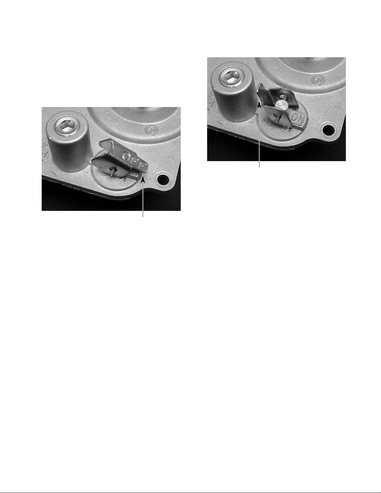
A manual oven shutoff valve is available on
the gas distribution valve to shut off the gas to
the oven burners. This valve will not affect the
operation of the cooktop burners. When the
lever is down, the gas to the oven burners is
turned off.
When the lever is raised, the gas to the oven
burners is turned on.
Manual Valve Lever
Raised (Gas On)
Manual Valve Lever
Down (Gas Off)
- 3 -
Page 8
BAKE & BROIL SOLENOIDACTIVATED PORTS
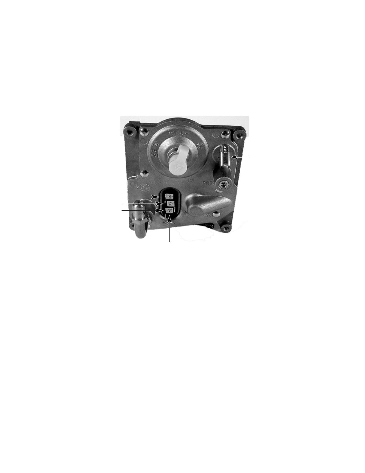
The bake and broil gas supply ports are opened
and closed by electrically-operated solenoids.
When voltage is received from the spark
ignition control for the bake or broil function,
(8-18 VDC), the solenoid for that function is
activated, and the valve opens to allow gas
Electrical Terminals:
Broil = 1/8˝ wide
Common = 1/4˝ wide
Bake = 3/16˝ wide
flow to the burner. The electrical connections
at the valve consist of three terminals, each
one sized differently to prevent incorrect wiring (see below).
The solenoids require special voltage/current
(8 - 18 VDC) from the direct spark ignition control to operate properly. IMPORTANT: Do not
attempt to operate the solenoids with any
other voltage supply.
Manual Oven
Shutoff Valve
216 Ω Resistance Across
Each Solenoid Terminal
8 to 18 VDC
NOTE: Always check
both solenoids. If either
solenoid is defective,
neither one will operate.
- 4 -
Page 9
L.P. GAS CONVERSION
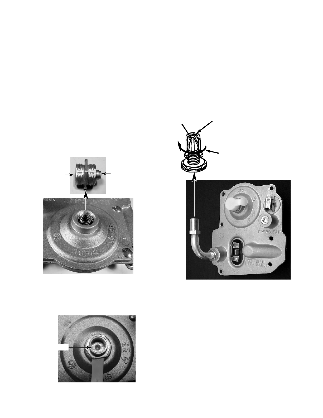
The range is manufactured to use natural gas.
To convert the range to use L.P. gas, the following steps are performed:
1. Turn off the gas and electrical supplies to
the range.
2. Remove the storage drawer from the
range.
3. Locate the gas distribution valve at the
rear of the range. To convert the gas
distribution valve:
a)Unscrew the conversion cap from the
gas distribution valve. Note the difference between the L.P. and natural gas
ends of the cap.
L.P. Gas
Natural Gas
4. To convert the bake burner:
a)Open the oven door and remove the
oven racks.
b)Use a 1/2" open-end wrench and turn
the orifice hood down snug onto the pin
(approximately 2-1/2 turns). DO NOT
OVERTIGHTEN THE ORIFICE. The
burner flame cannot be properly adjusted if this conversion is not made.
Pin
Orifice Hood
Natural Gas:
Unit is manufactured
for natural gas
L.P. Gas:
Turn down 2-1/2 turns in
this direction
b)Install the conversion cap on the gas
distribution valve with the L.P. side facing up (you will see L.P. stamped inside
the cap, as shown).
L.P. Gas
- 5 -
Page 10
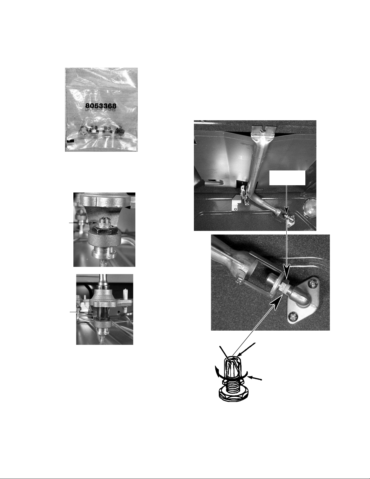
5. To convert the cooktop burners:
6. To convert the broil burner:
NOTE: The L.P. orifices for the cooktop burners are supplied in the literature pack inside
the oven.
a)Use an 8 mm socket and carefully re-
move the orifice spud from each of the
four burners.
Surface
Burner
Orifice
a)Open the oven door and remove the
oven racks.
b)Use a 1/2" open-end wrench and turn
the orifice hood down snug onto the pin
(approximately 2-1/2 turns). DO NOT
OVERTIGHTEN THE ORIFICE. The
burner flame cannot be properly adjusted if this conversion is not made.
Broil Burner
Orifice
8mm
Socket
b)Install the four L.P. gas orifices in the
burners.
Pin
Orifice Hood
Natural Gas:
Unit is manufactured
for natural gas
L.P. Gas:
Turn down 2-1/2 turns in
this direction
7. Reinstall the storage drawer and oven
racks.
- 6 -
Page 11
DIRECT SPARK IGNITION CONTROL
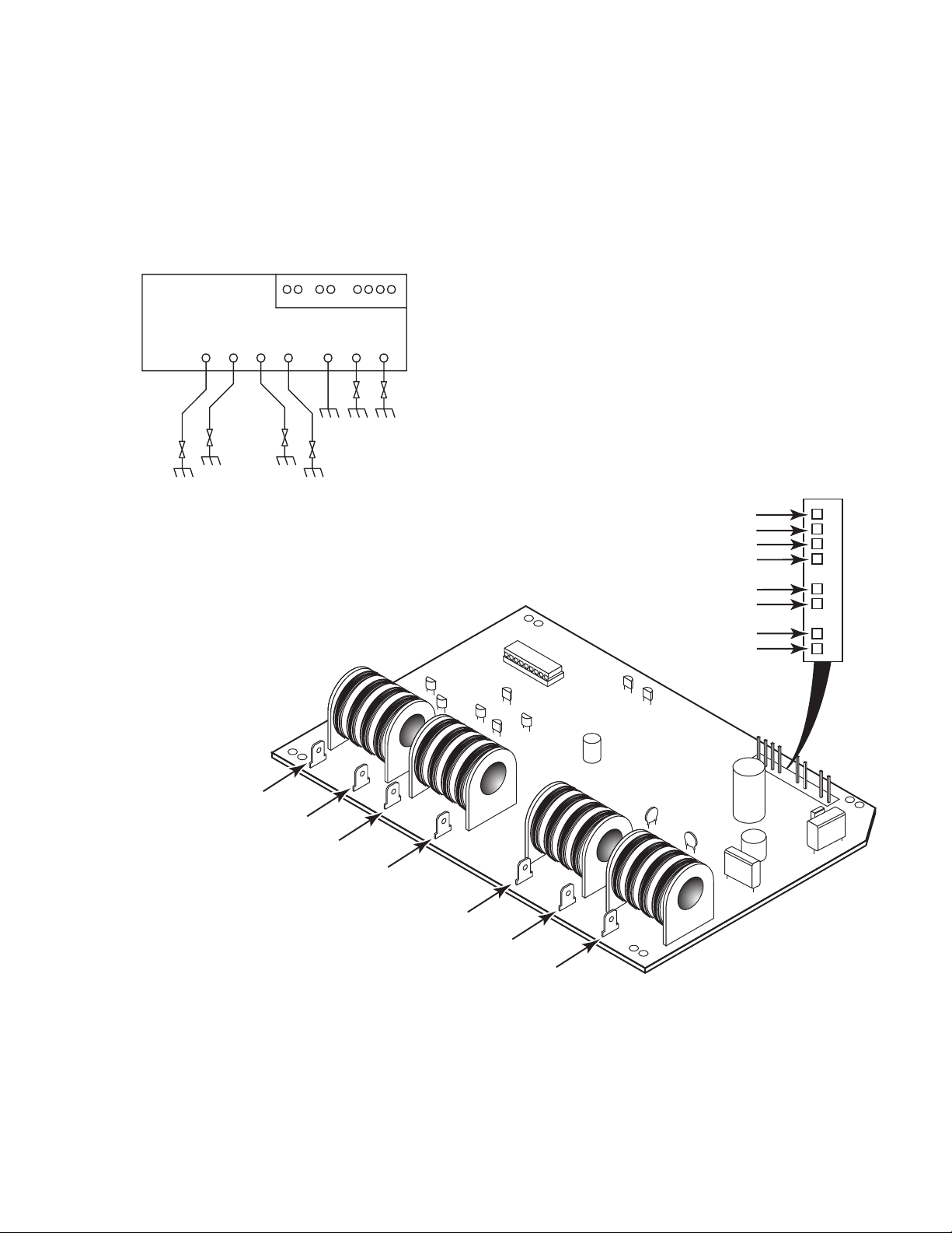
The Direct Spark Ignition (DSI) Control interfaces with the Electronic Oven Control for the
Bake, Broil, and Self-Clean functions. The DSI
also interfaces with the four cooktop burner ignition switches, to provide ignition for the
cooktop.
DIRECT SPARK
IGNITION CONTROL
TOP BURNERS
J1
10-PIN CONNECTOR
GND BAKE BROIL
643217910
The DSI control uses a self-diagnostic test to
verify that the oven ignition system is working
properly. It will also continually monitor the
flame presence within the oven. The DSI control operates on 102 to 132 VAC. All input and
output testing is performed at the J1 connector (see below).
J1
Bake Valve Output
Valve Common
Broil Valve Output
Neutral
1
2
3
4
Right Front Spark Output
Left Front Spark Output
Right Rear Spark Output
Left Rear Spark Output
DIRECT SPARK IGNITION
ELECTRONIC CONTROL
T4
J7
J8
Chassis Ground
Bake Burner Spark Output
T3
J5
J6
Broil Burner Spark Output
J2
T2
J4
Top Burner Input
T1
J3
Bake Input
Broil Input
L1
6
7
9
10
J1
- 7 -
Page 12
ELECTRONIC SPARK IGNITION
COOKTOP BURNER OPERATION
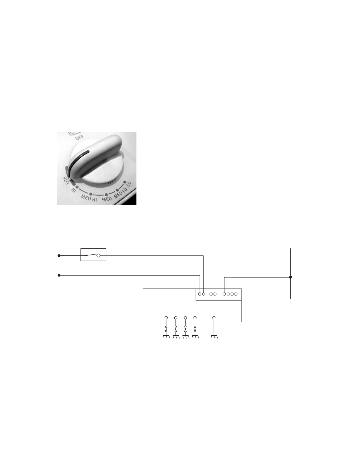
The top burner spark ignition system is initiated when the burner control is turned to the
LITE position.
120 VAC is supplied through the ignition switch
from the L1 side of the circuit to the direct spark
ignition control at input J1-9 on the control. The
circuit is completed through output pin J1-4 to
the neutral side of the circuit.
This 120 VAC is detected by the control, and
generates two sparks-per-second to all of the
top burners. Note that in the strip circuit below, 120 VAC is present at the control at all
times through input pin J1-10, and output pin
J1-4.
120 VAC is required to:
a)Monitor the internal self-diagnostics of
the control board.
b)Monitor the flame safety circuits to both
of the oven burners.
NOTE: The top burners are operator-monitored, and do not require electronic monitoring.
Cooktop Strip Circuit
L1
BK
BK
IGNITION
SWITCH
N
R
W
DIRECT SPARK
IGNITION CONTROL
TOP BURNERS GND
J1
10-PIN CONNECTOR
643217910
- 8 -
Page 13
OVEN BURNER OPERATION
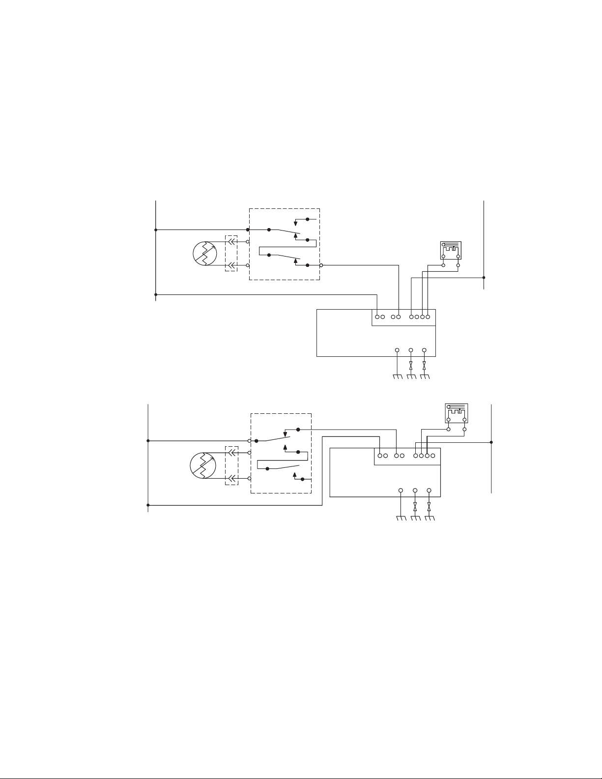
The spark ignition for the oven burners is
started at the Electronic Oven Control (ERC).
As the ERC is programmed for Bake or Broil,
the appropriate relay is closed on the ERC.
120 VAC is provided from L1, through the ERC
relay(s) to the direct spark ignition control at
input pin J1-6 (Bake), or J1-7 (Broil), to the
neutral side of the circuit, through output pin
J1-4.
L1
BK
OVEN
TEMP
SENSOR
BK
OVEN CONTROL (ERC)
BROIL
P1-4
P1-5
RELAY
RELAY
P2-1
V
V
BAKE
This 120 VAC is used to generate two sparksper-second to both oven burners. The 120 volts
AC is also stepped-down to between 8 and 18
VDC through pins J1-1 and J1-2 (Bake), and
pins J1-3 and J1-2 (Broil). This DC voltage
opens the gas distribution valve, and provides
gas to the appropriate oven burner.
N
BAKE VALVE
P2-4
R
R
OR
W
Bake Operation
L1
BK
OVEN
TEMP
SENSOR
BK
OVEN CONTROL (ERC)
BROIL
P2-1
V
V
RELAY
P1-4
P1-5
BAKE
RELAY
Broil Operation
Monitoring System
When power is applied to the range, a safety
delay of 40 seconds takes place before the
direct spark ignition control becomes operational. The 40 second delay allows any unused
gas inside the oven cavity to dissipate before
a spark is activated. When the Bake or Broil
operation is activated, the direct spark ignition
control initiates an “internal self-test” and “flame
safety check.” The flame safety check takes
place anytime there is a flame present at either oven burner.
DIRECT SPARK
IGNITION CONTROL
P2-2
DIRECT SPARK
IGNITION CONTROL
J1
J1
643217910
10-PIN CONNECTOR
GND BAKE BROIL
643217910
10-PIN CONNECTOR
GND BAKE BROIL
BROIL VALVE
BUBU
OR
N
W
The self-test checks both solenoids on the gas
distribution valve to verify that they are properly connected. If they are not, the control will
turn the oven off, or lock it out. If the test is
successful, the control will then open the appropriate valve, and initiate sparking at the
burner ignitor. Both the bake and broil ignitors
spark simultaneously. Sparking will not occur
until the gas distribution valve opens.
- 9 -
Page 14
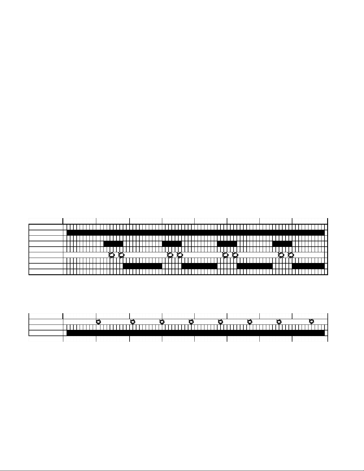
Once the gas has ignited, the “flame safety
circuit” will monitor the flame at the burner to
make sure it is present. If a flame is not present
at the burner:
a) The control will allow the ignitor to spark
for 4 seconds.
b)A 40 second delay to dissipate any un-
used gas inside the oven will occur.
The ignition attempt will occur three times. If
the burner does not ignite after the three attempts, the system will “lockout” (see the Timing Chart below).
Lockout
c) A flame is present within the oven for
more than 10 seconds after the gas
valve is off.
d)The flame is unexpectedly lost for any
reason after being established. NOTE:
If this occurs, a lockout condition will occur after 30 seconds with no attempt to
reignite.
During the lockout, the gas distribution valve
and ignition are turned off. All lockouts can be
reset by pressing the OFF/Cancel keypad on
the Electronic Oven Control. NOTE: There will
be no indication on the electronic oven control
display showing a lockout condition.
The control will perform an oven system lockout if:
a)Any of the self-test checks fail.
b)The oven fails to ignite after three igni-
tion attempts.
Time (sec)
Valve open
Charge Cap
Spark
Flame Sense
0 0.5 1.0 1.5 2.0 2.5 3.0 3.5
Timing Chart (Oven Burners)
Timing Sequence = 4 Seconds
3 Attempts Before Lockout
Time (sec)
Top Spark
0 0.5 1.0 1.5 2.0 2.5 3.0 3.5
Note To Technician: The cooktop spark operates normally even when the oven is in the
“lockout” mode. If the oven does not appear to
work at all, verify the operation of the cooktop
spark. If the cooktop spark is working correctly,
the DSI control is most likely okay, and the
problem is somewhere else in the range.
Valve Open
Timing Chart (Cooktop Burners)
- 10 -
Page 15
SECTION 2SECTION 2
SECTION 2
SECTION 2SECTION 2
COMPONENT ACCESS
This section instructs you on how to service the direct spark ignition system components inside the
Gas Range.
REMOVING THE DIRECT SPARK IGNITION CONTROL
4. Disconnect the wire connectors from the
direct spark ignition control.
WARNING
ELECTRICAL SHOCK HAZARD
Disconnect power before servicing the range.
Replace all panels before operating range.
Failure to do so can result in death or electrical shock.
FIRE HAZARD
Shut off gas supply line valve before servicing the range.
Check all gas line connections and replace
all panels before operating the range.
Failure to do so could result in explosion, fire,
or other injury.
CAUTION: When you work on the gas range,
be careful when handling the sheet metal parts.
Sharp edges may be present, and you can cut
yourself if you are not careful.
1. Turn off the gas to the range and disconnect the power cord from the wall outlet.
2. Pull the range away from the wall so you
can access the back of the unit.
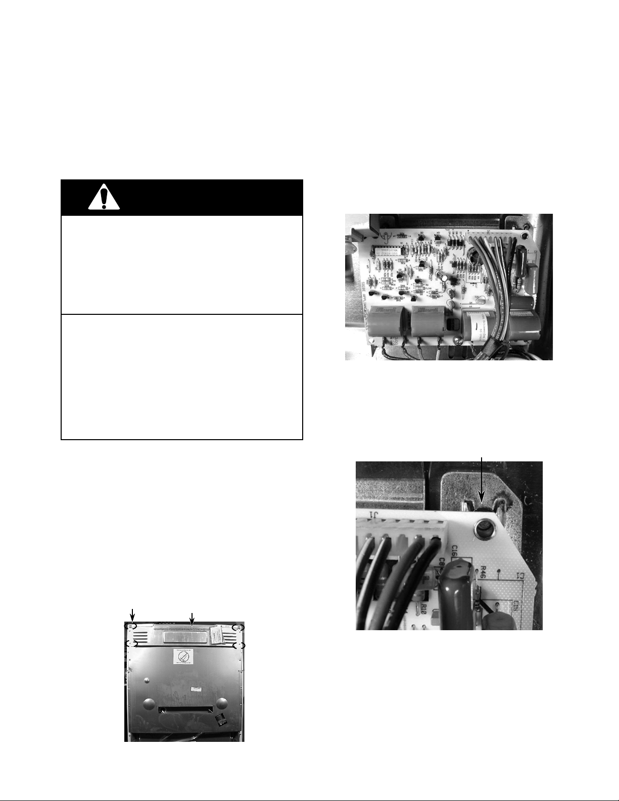
3. Remove the top rear cover (4 screws).
Screw (1 of 4)
Top Rear Cover
5. Remove the mounting screws.
6. Slide the two top pins out of the bracket
slots and remove the control from the
bracket.
Board Pin
In Slot
- 11 -
Page 16

REMOVING THE GAS DISTRIBUTION VALVE
WARNING
ELECTRICAL SHOCK HAZARD
Disconnect power before servicing the range.
Replace all panels before operating range.
Failure to do so can result in death or electrical shock.
FIRE HAZARD
Shut off gas supply line valve before servicing the range.
Check all gas line connections and replace
all panels before operating the range.
Failure to do so could result in explosion, fire,
or other injury.
3. Remove the gas outlet lines from the gas
distribution valve with a 9/16˝ open-end
wrench.
4. Remove the four mounting screws from
the gas distribution valve.
Gas Outlet
Screws
Gas
Distribution
Valve
CAUTION: When you work on the gas range,
be careful when handling the sheet metal parts.
Sharp edges may be present, and you can cut
yourself if you are not careful.
1. Turn off the gas to the range and disconnect the power cord from the wall outlet.
2. Pull the range away from the wall so you
can access the back of the unit.
Gas Distribution Valve
(Back of Range)
Gas Outlet
5. Lower the gas distribution valve so that it
is free of the bake burner, and lay it down,
as shown below.
6. Remove the electrical connections. NOTE:
The terminals are different sizes to prevent miswiring (see page 4).
Screws
- 12 -
Page 17
SECTION 3SECTION 3
SECTION 3
SECTION 3SECTION 3
COMPONENT TESTING
DIRECT SPARK IGNITION CONTROL
WARNING
Electrical Shock Hazard
Voltage is present during these tests.
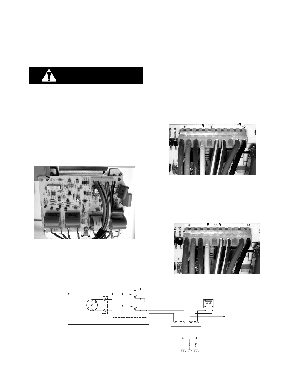
TEST PROCEDURE
Voltage Tests
3. If the top burners spark, proceed to step 4.
Touch the test leads to the J1 connector at
terminals 4 (white) and 10 (black). The AC
voltmeter should indicate 120 VAC. If not,
check for the proper voltage at the power
supply outlet, and check the main wiring
harness.
4 (white)
10 (black)
Bake Function
1. Set the voltmeter to read 120 VAC.
2. Program the range for the Bake operation.
J1 Connector
Bake Strip Circuit
J1 Connector
4. Touch the test leads to the J1 connector at
terminals 4 (white) and 6 (red/white). The
AC voltmeter should indicate 120 VAC. If
not, check the electronic oven control for
proper operation.
4 (white)
6 (red/white)
J1 Connector
L1
BK
SENSOR
BK
OVEN
TEMP
OVEN CONTROL (ERC)
P2-1
V
V
RELAY
P1-4
P1-5
BROIL
BAKE
RELAY
P2-4
- 13 -
R
J1
10-PIN CONNECTOR
DIRECT SPARK
IGNITION CONTROL
643217910
GND BAKE BROIL
BAKE VALVE
R
OR
N
W
Page 18
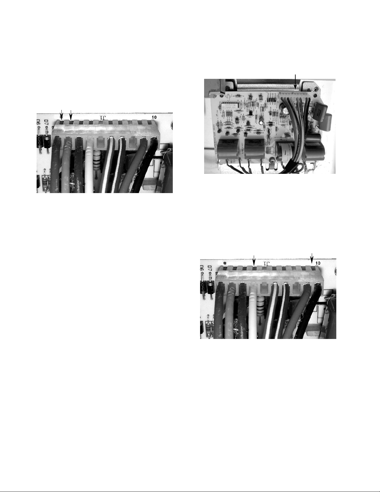
5. Set the voltmeter to read between 8 and
18 volts DC.
6. Touch the test leads to the J1 connector at
terminals 1 (red) and 2 (orange). The DC
voltmeter should indicate between 8 and
18 volts DC*. If not, replace the DSI control.
2 (orange)1 (red)
J1 Connector
* When power is applied to the range, a safety delay
of 40 seconds takes place before the direct spark
ignition control becomes operational. The operation will last for a period of 4 seconds, and the direct
spark ignition will again turn off (see the “Timing
Chart” for the oven burners on page 10).
Broil Function
1. Set the voltmeter to read 120 VAC.
2. Program the range for the Broil operation.
J1 Connector
3. If the top burners spark, proceed to step 4.
Touch the test leads to the J1 connector at
terminals 4 (white) and 10 (black). The AC
voltmeter should indicate 120 VAC. If not,
check for the proper voltage at the power
supply outlet, and check the main wiring
harness.
4 (white)
10 (black)
J1 Connector
- 14 -
Page 19
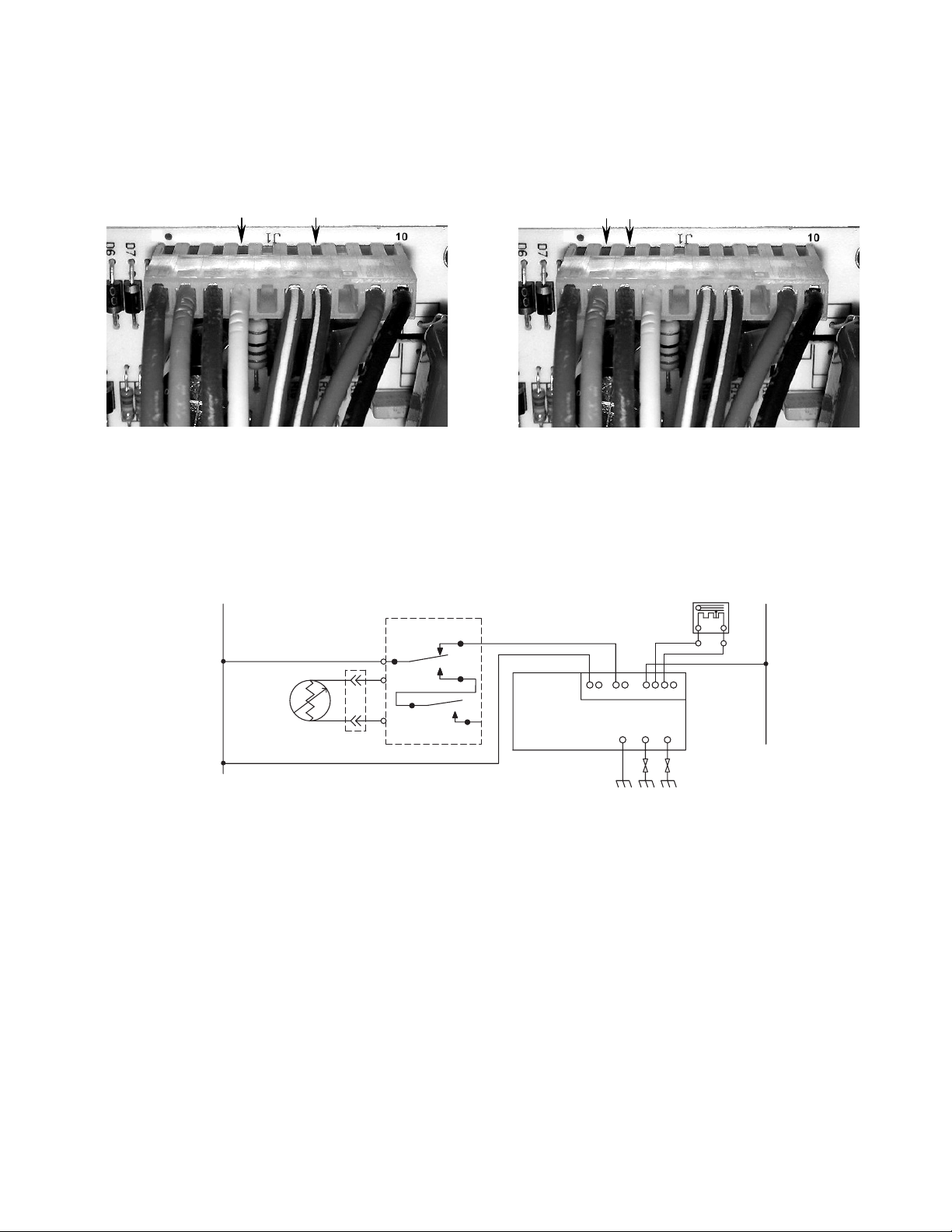
4. Touch the test leads to the J1 connector at
terminals 4 (white) and 7 (blue/white). The
AC voltmeter should indicate 120 VAC. If
not, check the electronic oven control for
proper operation.
4 (white)
7 (blue/white)
6. Touch the test leads to the J1 connector at
terminals 2 (orange) and 3 (blue). The DC
voltmeter should indicate between 8 and
18 volts DC*. If not, replace the DSI control.
2 (orange)
3 (blue)
J1 Connector
5. Set the voltmeter to read between 8 and
18 volts DC.
Broil Strip Circuit
L1
BK
OVEN
TEMP
SENSOR
BK
OVEN CONTROL (ERC)
BROIL
P2-1
V
V
RELAY
P1-4
P1-5
BAKE
RELAY
J1 Connector
* When power is applied to the range, a safety delay
of 40 seconds takes place before the direct spark
ignition control becomes operational. The operation will last for a period of 4 seconds, and the direct
spark ignition will again turn off (see the “Timing
Chart” for the oven burners on page 10).
BROIL VALVE
N
P2-2
DIRECT SPARK
IGNITION CONTROL
J1
10-PIN CONNECTOR
GND BAKE BROIL
643217910
BUBU
OR
W
- 15 -
Page 20
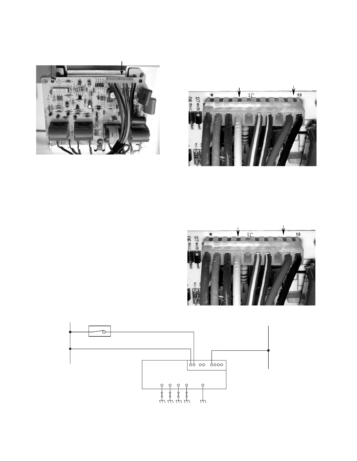
Cooktop Function
1. Set the voltmeter to read 120 VAC.
J1 Connector
2. Turn one of the cooktop burner valves to
the LITE position.
3. Touch the test leads to the J1 connector at
terminals 4 (white) and 10 (black). The AC
voltmeter should indicate 120 VAC. If not,
check for the proper voltage at the power
supply outlet, and check the main wiring
harness.
4 (white)
10 (black)
J1 Connector
4. Touch the test leads to the J1 connector at
terminals 4 (white) and 9 (red). The AC
voltmeter should indicate 120 VAC. If not,
check the ignition switch and the main
wiring harness.
Cooktop Strip Circuit
L1
BK
BK
IGNITION
SWITCH
4 (white)
9 (red)
J1 Connector
N
R
W
DIRECT SPARK
IGNITION CONTROL
TOP BURNERS GND
J1
10-PIN CONNECTOR
643217910
- 16 -
Page 21
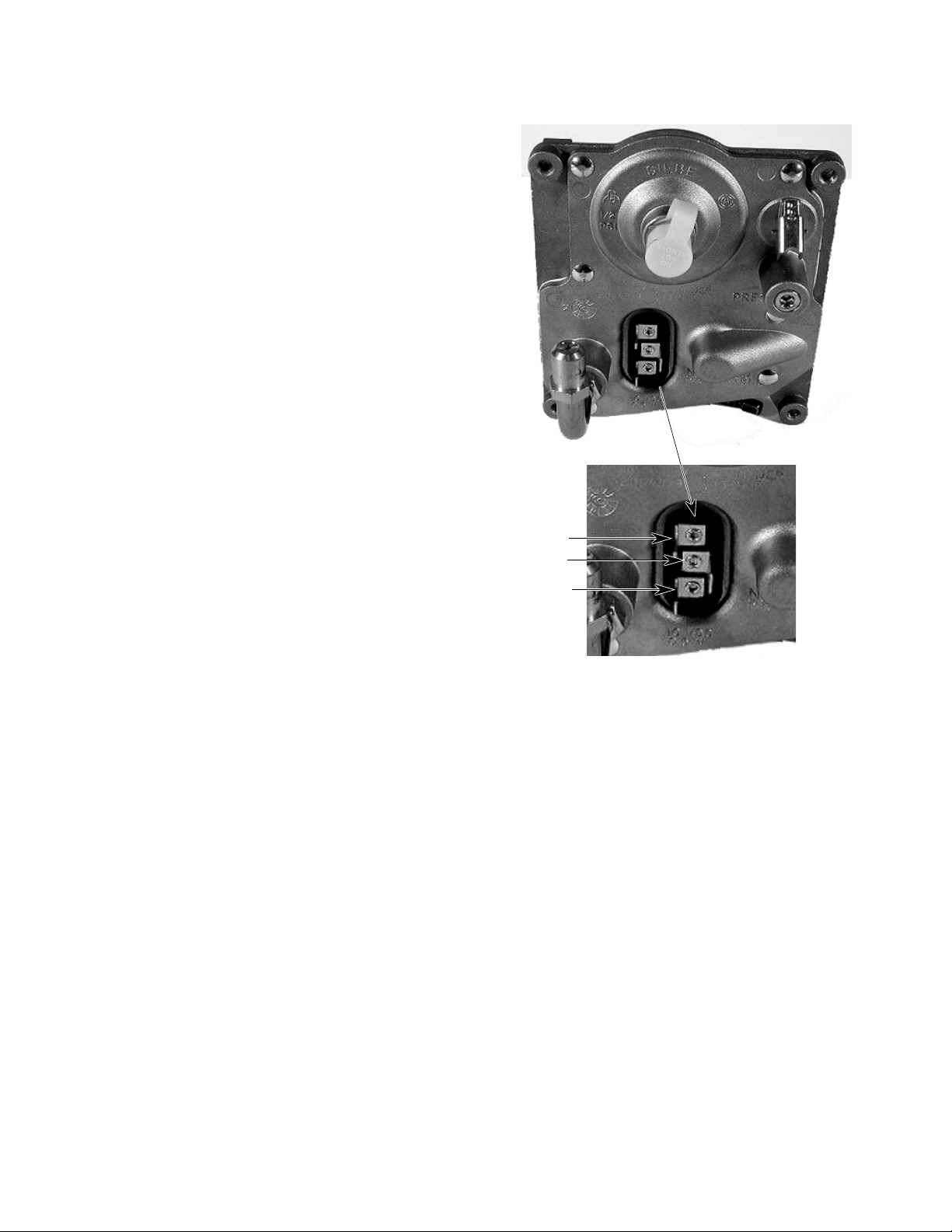
GAS DISTRIBUTION VALVE
TEST PROCEDURE
Solenoid Resistance Tests
1. Disconnect power from the range.
2. Set the ohmmeter to the R x 100 scale.
3. Touch the ohmmeter terminals to terminals 1 and 2 (Broil). The ohmmeter should
read 216 Ω ±30.
4. Touch the ohmmeter terminals to terminals 3 and 2 (Bake). The ohmmeter should
read 216 Ω ±30.
NOTE: Always check both solenoids. If one of
the solenoids is defective, neither one will
operate.
1
2
3
- 17 -
Page 22

— NOTES —
- 18 -
Page 23
N
SECTION 4SECTION 4
SECTION 4
SECTION 4SECTION 4
WIRING DIAGRAM & STRIP CIRCUITS
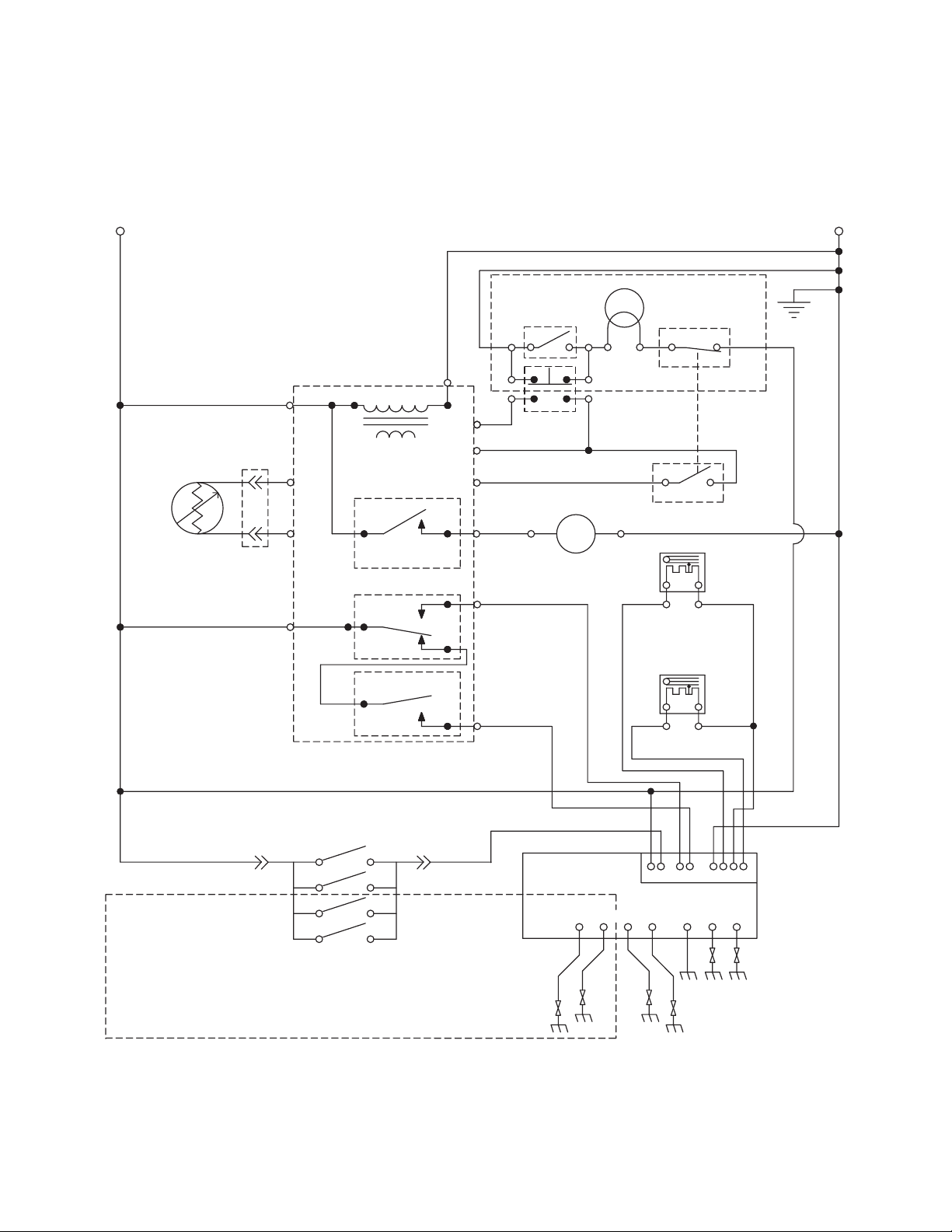
WIRING DIAGRAM
L1
BK
OVEN
TEMP
SENSOR
1080 W @ 72˚F
BK
OVEN LT.
ROCKER SW.
W
P1-2
P1-3
P1-1
P6-4
P2-2
P2-4
(IF EQUIPPED)
Y
DOOR
LIGHT SW.
GY
BU
LATCH DRIVE
BR
MOT
BU
R
W
W
Y
W
W
W
OVEN CONTROL
P6-1
TRANSFORMER
V
V
P2-1
P1-4
P1-5
LATCH RELAY
BROIL
RELAY
BAKE
RELAY
P6-3
DOOR
LATCH SW.
(IF EQUIPPED)
BK BK
GY
DOOR
LATCH SWITCH
BU
BROIL VALVE
R
BAKE VALVE
OR
OR
N/C
N/O
GND
W
BK
SURFACE BURNER
IGNITION SWITCHES
BK R
SEALED BURNER
UNITS EQUIPPED
WITH 4 IGNITORS,
OPEN BURNER UNITS
WITH 2 IGNITORS
NOTE: Drawing shows door latch switch in the Cook
position with oven door open, oven Off, and light On.
- 19 -
DIRECT SPARK
IGNITION CONTROL
TOP BURNERS
J1
643217910
10-PIN CONNECTOR
GND BAKE BROIL
PART NO. 8273173
Page 24
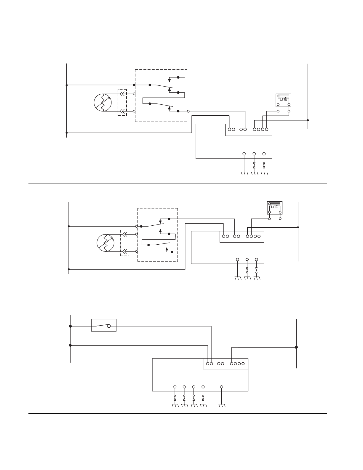
STRIP CIRCUITS
BAKE
BROIL
L1
L1
BK
OVEN
TEMP
SENSOR
BK
BK
SENSOR
BK
OVEN
TEMP
OVEN CONTROL (ERC)
P2-1
V
V
V
V
P1-4
P1-5
OVEN CONTROL (ERC)
BROIL
P2-1
RELAY
P1-4
P1-5
BROIL
RELAY
BAKE
RELAY
BAKE
RELAY
P2-4
DIRECT SPARK
IGNITION CONTROL
P2-2
DIRECT SPARK
IGNITION CONTROL
R
J1
J1
10-PIN CONNECTOR
643217910
10-PIN CONNECTOR
GND BAKE BROIL
BROIL VALVE
BUBU
643217910
GND BAKE BROIL
BAKE VALVE
R
OR
OR
W
N
W
N
COOKTOP
L1
BK
BK
IGNITION
SWITCH
N
R
W
DIRECT SPARK
IGNITION CONTROL
TOP BURNERS GND
J1
10-PIN CONNECTOR
643217910
- 20 -
Page 25
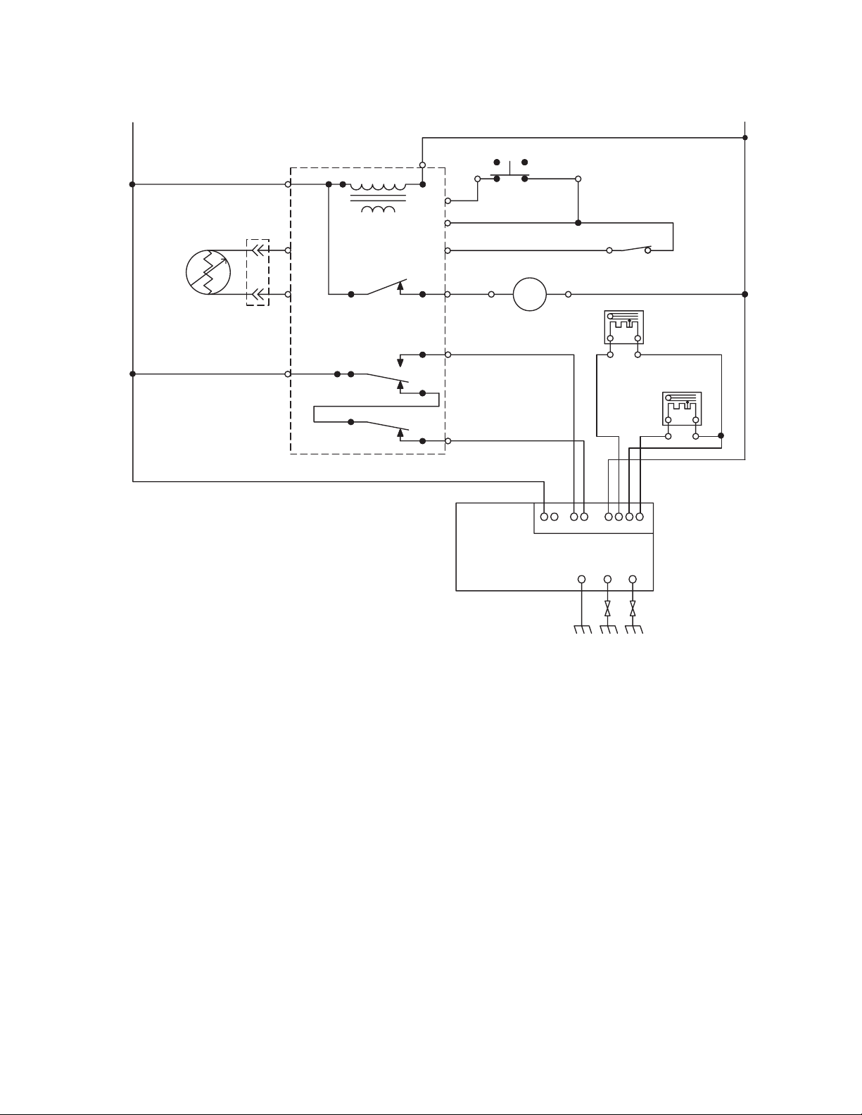
CLEAN
L1
OVEN
TEMP
SENSOR
1080 W @ 72˚F
V
BK
W
OVEN CONTROL
P6-1
TRANSFORMER
V
P2-1
P1-4
P1-5
LATCH
RELAY
BROIL
RELAY
BAKE
RELAY
P6-3
P1-2
Y
P1-3
P1-1
P6-4
BR
P2-2
P2-4
DIRECT SPARK
IGNITION CONTROL
DOOR SWITCH
GY
BU
LATCH DRIVE
MOT
BU
R
J1-
10-PIN CONNECTOR
Y
GY
DOOR
LATCH SW
W
BU
643217910
GND BAKE BROIL
N/O
BROIL VALVE
OR
BAKE VALVE
R
OR
N
- 21 -
Page 26

— NOTES —
- 22 -
Page 27
SECTION 5SECTION 5
SECTION 5
SECTION 5SECTION 5
TECH TIPS
DIAGNOSTIC FLOW CHARTS
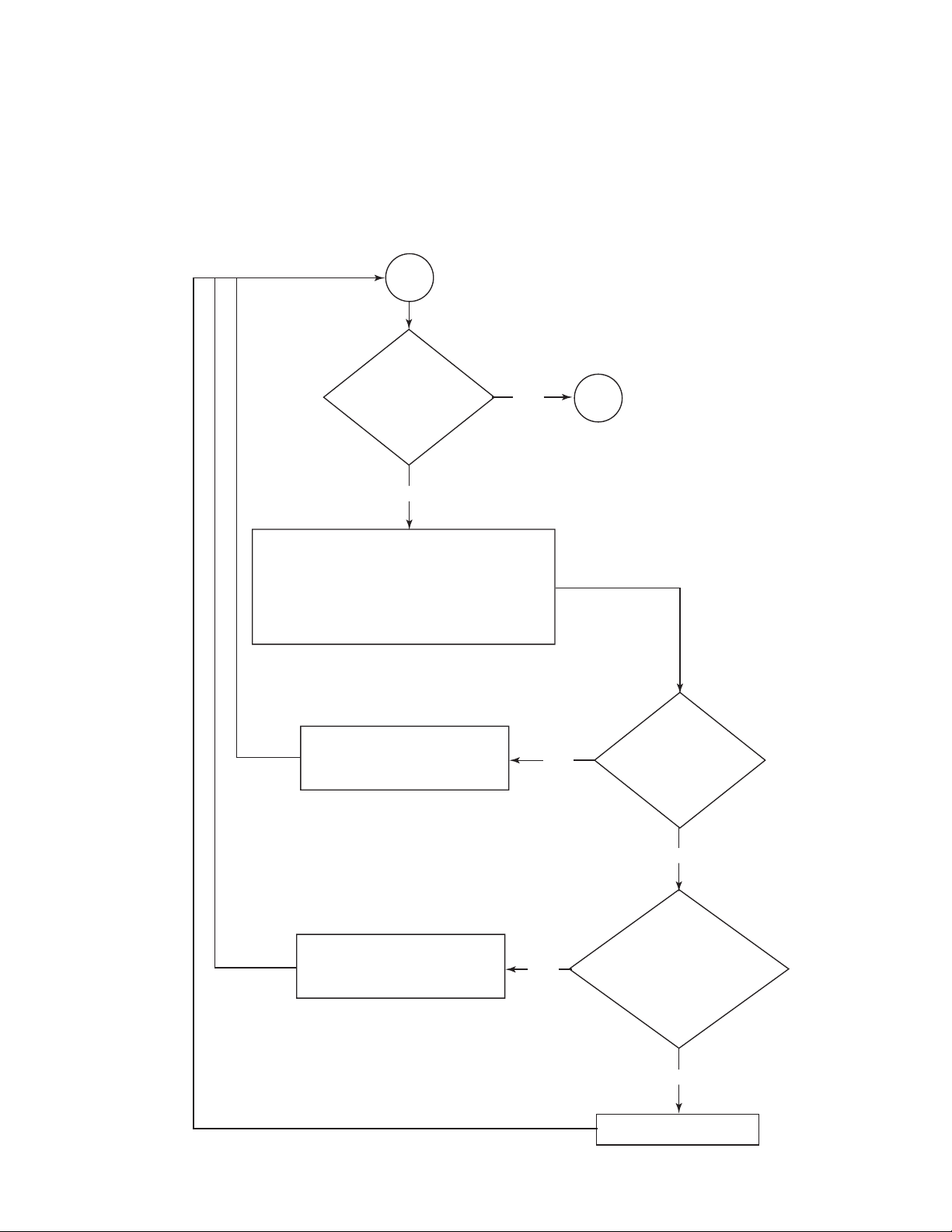
COOKTOP
Start
Does cooktop
spark properly?
no
Check the high voltage igniter wires for
continuity and proper connections from DSI
control to igniters. Make sure the burner
caps are the correct size and are properly
oriented. Also, if the supply voltage is
less than 102 VAC, the spark might not occur.
NOTE: The range must be plugged in for
at least 40 seconds before this test can begin.
yes
Done
Diagnose the main wiring
harness. 120 VAC should
always be present at this point.
Diagnose the cooktop wiring
harness. Check the cooktop
switches for the proper function.
- 23 -
no
no
Is 120 VAC
present from J1-4
to J1-10?
yes
With the cooktop
knob in LITE, is
120 VAC present
from J1-4 to J1-9?
yes
Replace the DSI control.
Page 28
BAKE
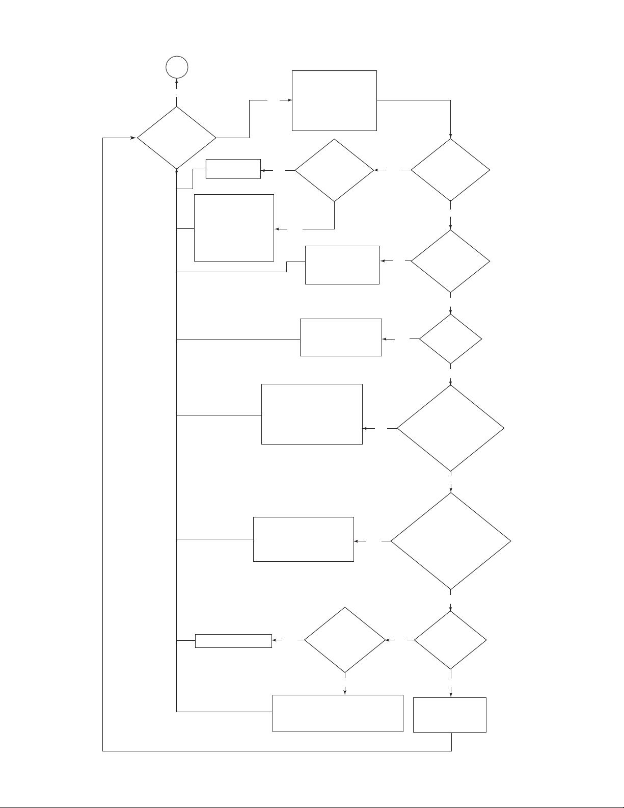
Done
yes
Does the Bake
cycle function
properly?
Replace the gas
distribution valve.
Check the igniter for
continuity. If not okay,
replace the igniter. If
the supply polarity is
correct, check the Bake
ignition wire for a loose
connection. If okay,
replace the DSI control.
Check the polarity of
the supply voltage. Even
if no ground is connected,
no
the DSI control will not be
able to sense the presence
of a flame at the igniter if
the polarity is reversed.
no
continue after a
flame is present?
yes
wiring harness and/or
Does the spark
Diagnose the main
the electronic oven
control (ERC).
yes
Does the Bake
burner establish
a flame and then
turn off?
no
Is 120 VAC
no
present from
J1-4 to J1-6?
yes
Diagnose the ERC.
The DSI control will lockout
if a call for Bake & Broil
exists simultaneously.
Measure the resistance at
the distribution valve. If different
than measured at the DSI control,
diagnose the wiring harness.
If resistances are the same as
measured at the DSI control,
replace the valve.
If the voltage is higher than
18 VDC, check the main wiring
harness for bad connections.
If okay, replace the
distribution valve.
yes
yes
no
Wait 40 seconds, then start a Bake
Is 120 VAC
present from
J1-4 to J1-7?
Turn the ERC off.
Test the distribution valve
for continuity at J1-1 and J1-2,
then J1-2 and J1-3. Are
both resistances
216 Ω ±30?
yes
Connect a DC voltmeter
to J1-1 (+) and J1-2 (–).
cycle. 6 seconds later, does
the meter indicate
8 to 18 VDC?
no
no
Replace the DSI control.
yes
ceramics. If cracks are found, replace
the igniter. Diagnose the Bake igniter
wiring harness. If okay, replace the control.
but not the Bake?
yes
Check the igniter for cracks in the
Does spark
occur at the Broil igniter
- 24 -
no
Does spark
occur at the igniter?
The igniter position is
out of tolerance for the
proper ignition. Replace
the igniter and burner.
yes
Page 29
BROIL
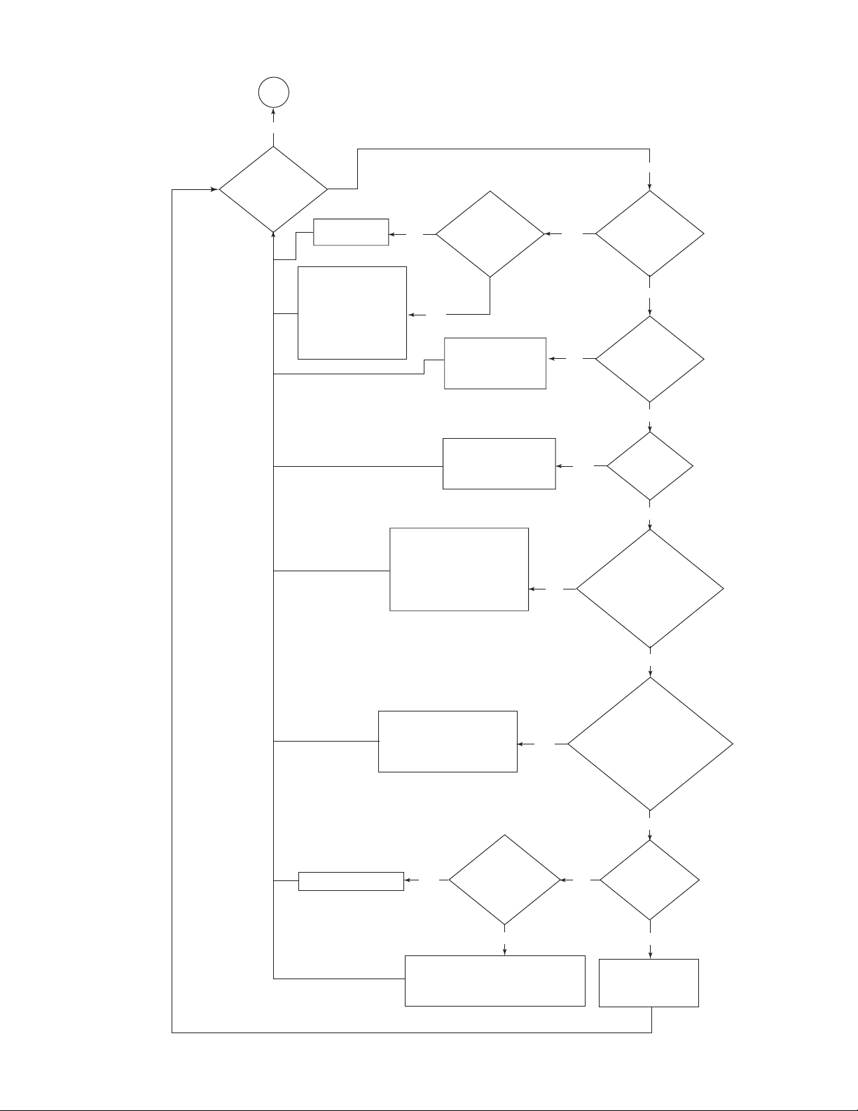
Done
yes
Does the Broil
cycle function
properly?
Replace the gas
distribution valve.
Check the igniter for
continuity. If not okay,
replace the igniter. If
the supply polarity is
correct, check the Broil
ignition wire for a loose
connection. If okay,
replace the DSI control.
no
Does the spark
no
continue after a
flame is present?
yes
Diagnose the main
wiring harness and/or
the electronic oven
control (ERC).
yes
no
Does the Broil
burner establish
a flame and then
turn off?
no
Is 120 VAC
present from
J1-4 to J1-7?
yes
Diagnose the ERC.
The DSI control will lockout
if a call for Bake & Broil
exists simultaneously.
Measure the resistance at
the distribution valve. If different
than measured at the DSI control,
diagnose the wiring harness.
If resistances are the same as
measured at the DSI control,
replace the valve.
If the voltage is higher than
18 VDC, check the main wiring
harness for bad connections.
If okay, replace the
distribution valve.
yes
yes
no
Wait 40 seconds, then start a Broil
Is 120 VAC
present from
J1-4 to J1-6?
Turn the ERC off.
Test the distribution valve
for continuity at J1-1 and J1-2,
then J1-2 and J1-3. Are
both resistances
216 Ω ±30?
Connect a DC voltmeter
to J1-3 (+) and J1-2 (–).
cycle. 6 seconds later, does
the meter indicate
8 to 18 VDC?
no
yes
no
Replace the DSI control.
yes
ceramics. If cracks are found, replace
the igniter. Diagnose the Broil igniter
wiring harness. If okay, replace the control.
but not the Broil?
yes
Check the igniter for cracks in the
Does spark
occur at the Bake igniter
- 25 -
no
Does spark
occur at the igniter?
The igniter position is
out of tolerance for the
proper ignition. Replace
the igniter and burner.
yes
 Loading...