

Page 1
MICROWAVE
OVEN HOOD
COMBINATION
KM-30
8178573
i
Page 2

FORWARD
This Job Aid, “Whirlpool Microwave Oven Hood Combination,” (Part No. 8178573), provides the
In Home Service Professional with information on the operation and service of the Whirlpool Micro-
wave Oven Hood Combination. It is to be used as a training Job Aid and Service Manual. For specic
information on the model being serviced, refer to the “Use and Care Guide,” or “Tech Sheet” provided
with the microwave oven.
The Wiring Diagrams and Strip Circuits used in this Job Aid are typical and should be used for
training purposes only. Always use the Wiring Diagram supplied with the product when servicing
the unit.
GOALS AND OBJECTIVES
The goal of this Job Aid is to provide detailed information that will enable the In Home Service Professional to properly diagnose malfunctions and repair the Microwave Oven Hood Combination.
The objectives of this Job Aid are to:
• Understand and follow proper safety precautions.
• Successfully troubleshoot and diagnose malfunctions.
• Successfully perform necessary repairs.
• Successfully return the microwave oven to proper operational status.
WHIRLPOOL CORPORATION assumes no responsibility for any repairs made
on our products by anyone other than Authorized In Home Service Professionals.
Copyright © 2006, Whirlpool Corporation, Benton Harbor, MI 49022
ii
Page 3

TABLE OF CONTENTS
GENERAL ................................................................................................................................. 1-1
Important Safety Information ............................................................................................1-1
Warning to In Home Service Professionals ...................................................................... 1-2
Precautions To Be Observed Before and During Servicing
to Avoid Possible Exposure to Excessive Microwave Energy .......................................... 1-3
R.F. Leakage Test ............................................................................................................. 1-4
Whirlpool Model Number Designations ............................................................................1-5
Whirlpool Serial Number Designations ............................................................................. 1-6
Model & Serial Number Label and Tech Sheet Locations ................................................ 1-6
Specications .................................................................................................................... 1-7
Whirlpool Microwave Oven Warranty ................................................................................1-10
INSTALLATION INFORMATION ...............................................................................................
Hood Fan Motor Mounting Positions ................................................................................2-1
THEORY OF OPERATION ........................................................................................................ 3-1
Air Flow Paths ................................................................................................................... 3-1
COMPONENT ACCESS ...........................................................................................................
Component Locations ....................................................................................................... 4-1
Removing the Turntable Motor & Hood (Cooktop) Lamp Assembly ................................. 4-2
Removing the Control Panel & Control Board .................................................................. 4-4
Removing the Motor Capacitor and Line Fuse ................................................................. 4-6
Removing the Door Switches ...........................................................................................4-6
Removing the Oven Cavity Lamp and Charcoal Filter ...................................................... 4-8
Removing the Oven Rack Retainers ................................................................................4-9
Removing the Outer Cabinet ............................................................................................ 4-10
Removing the Thermostats and Thermistor ...................................................................... 4-11
Removing the Magnetron .................................................................................................4-12
Removing the High-Voltage Transformer .......................................................................... 4-13
2-1
4-1
Removing the High-Voltage Diode and Capacitor ............................................................ 4-14
Removing the Oven Cavity Lamp Socket ......................................................................... 4-15
Removing the AC Line Filter ............................................................................................. 4-16
Removing the Hood Fan Motor and Humidity Sensor ...................................................... 4-17
Removing the Fuse Holder & Mounting Bracket ............................................................... 4-18
Removing the Door and Door Disassembly ...................................................................... 4-19
COMPONENT TESTING ...........................................................................................................
H.V. Transformer ............................................................................................................... 5-1
Magnetron ......................................................................................................................... 5-2
H.V. Capacitor ................................................................................................................... 5-2
H.V. Diode ......................................................................................................................... 5-3
iii
5-1
Page 4

TABLE OF CONTENTS - CONTINUED
Turntable Motor ................................................................................................................. 5-3
Humidity Sensor ...............................................................................................................5-4
Hood Exhaust Fan Motor .................................................................................................. 5-4
AC Line Filter .................................................................................................................... 5-5
Thermostats ...................................................................................................................... 5-5
DIAGNOSIS & TROUBLESHOOTING ..................................................................................... 6-1
Interlock Switch Checkout Procedures ............................................................................. 6-1
Touch Panel and Electronic Control Test .......................................................................... 6-2
Microwave Oven Power Output Test ................................................................................ 6-3
Failure Codes Indications ................................................................................................. 6-3
WIRING DIAGRAM & STRIP CIRCUITS ..................................................................................
Wiring Diagram - 8205889 - Sensor Model ......................................................................7-1
Wiring Diagram - 8205660 - Non Sensor Model ............................................................... 7-2
Strip Circuits .....................................................................................................................7-3
Microwave Cooking ..................................................................................................... 7-3
Hood Exhaust Fan On High Automatically .................................................................. 7-3
Hood Exhaust Fan On Low Speed.............................................................................. 7-3
Hood Exhaust Fan On High / Medium ........................................................................ 7-4
Microwave Oven Plugged In—Time of Day Displayed ............................................... 7-4
Door Open—Oven Cavity Light Is On ......................................................................... 7-4
Cooktop Light On High ................................................................................................ 7-4
Cooktop Light On Low (Night Light) ............................................................................ 7-4
7-1
iv
Page 5

GENERAL
IMPORTANT SAFETY INFORMATION
ELECTROSTATIC DISCHARGE
(ESD) SENSITIVE ELECTRONIC
ESD problems are present everywhere. ESD
may damage or weaken the electronic control
assembly. The new control assembly
may appear to work well after repair is nished,
but failure may occur at a later date
due to ESD stress.
IMPORTANT SAFETY
INSTRUCTIONS
Before touching any oven component or wiring,
always unplug the oven from its power
source and discharge the capacitor by using a
20,000 ohm discharge resistor or use an insulated plastic handle screwdriver to short across
the capacitor terminals.
Check that the unit is grounded before troubleshooting. Discharge any static charge from your
body by touching ground before handling any part
of the circuitry on the control board. Electrostatic
discharge may damage the control circuit.
Do not touch oven components or wiring during
operation. Attach meter leads with alligator
clips when making operational tests.
For continued protection against radiation
emission, replace only with these types of
switches: Primary (Interlock) Switch: SZM-V16FA-63 or VP-533A-OF; Secondary (Interlock)
Switch: SZM-V01-FA-32; Interlock (Monitor)
Switch: SZM-VI6-FA-62 or VP-532A-OF; Oven
Lamp Switch: SZM-V6-FA-31 or VP-331 AOD.
• Use an antistatic wrist strap. Connect
the wrist strap to a green ground connection
point or unpainted metal in the
appliance; or touch your nger repeatedly
to a green ground connection point
or unpainted metal in the appliance.
• Before removing the part from its package,
touch the antistatic bag to a green
ground connection point or unpainted
metal in the appliance.
• Avoid touching electronic parts or terminal
contacts. Handle the electronic
control assembly by the edges only.
• When repackaging the failed electronic
control assembly in an antistatic bag,
observe the above instructions.
It is neither necessary nor advisable to attempt
measurement of high voltage.
Attaching the adaptor ground terminal to the
wall receptacle cover screw does not ground
the appliance unless the cover screw is metal
and not insulated and the wall receptacle is
grounded through the house wiring.
1-1
Page 6

WARNING TO IN HOME SERVICE PROFESSIONALS
To avoid possible exposure to microwave
radiation or energy, visually check the oven for
damage to the door and door seal before
operating any oven. Use a microwave survey
meter to check the amount of leakage before
servicing. In the event the R.F. Ieakage exceeds
4 mw/cm2 at 5 cm, appropriate repair
must be made before continuing to service the
unit. Check interlock function by operating the
door latch. The oven cook cycle should cut off
before the door can be opened.
The door and latching assembly contains the
radio frequency energy within the oven. The
door is protected by three safety interlock
switches. Do not attempt to defeat them.
Under no circumstances should you try to
operate the oven with the door open.
• Proper operation of microwave ovens requires
that the magnetron be properly
assembled to the waveguide and cavity.
Never operate the magnetron unless it is
properly installed.
• Be sure the “RF” seal is not damaged and
is assembled around the magnetron dome
properly when installing the magnetron.
• Routine service safety procedures should
be exercised at all times.
• Untrained personnel should not attempt
service without a thorough review of test
procedures and safety information contained
in this Job Aid.
Whirlpool microwave ovens have a monitoring
system designed to ensure proper operation of
the safety interlock systems.
The interlock monitor switch will immediately
cause the oven fuse to blow if the door is
opened and the primary door interlock switch
and/or the secondary interlock switch contacts
fail in a closed position.
CAUTION: Replace a blown fuse with a 20
ampere class H fuse only.
Test the upper and lower door interlock
switches, cook relay and interlock monitor
switch (middle switch) for proper operation as
described in the component test procedures,
before replacing the blown oven fuse.
Do not attempt to repair sticking contacts
of any interlock switch, safety switch, or
Cook (Latch) relay. The components must
be replaced.
Any indication of sticking contacts during component tests requires replacement of that component to ensure reliability of the safety interlock
system.
NOTE: If the fuse is blown, the monitor, primary,
and secondary interlock switches must be replaced. Be sure they are properly connected.
1-2
Page 7

PRECAUTIONS TO BE OBSERVED BEFORE AND
DURING SERVICING TO AVOID POSSIBLE EXPOSURE
TO EXCESSIVE MICROWAVE ENERGY
A. Do not operate or allow the oven to be
operated with the door open.
B. Make the following safety checks on all
ovens to be serviced before activating the
magnetron or other microwave source,
and make repairs as necessary:
1) Interlock operation
2) Proper door closing
3) Seal and sealing surfaces (arcing,
wear, and other damage)
4) Damage to or loosening of hinges and
latches
5) Evidence of dropping or abuse
C. Before turning on the microwave power
for any service test or inspection within the
microwave generating components, check the
magnetron, wave guide or transmission
line, and cavity for proper alignment,
integrity, and connections.
D. Any defective or misadjusted components
in the interlock, monitor, door seal, and
microwave generation and transmission
systems shall be repaired, replaced, or
adjusted, using procedures described in
this Job Aid, before the oven is released to
the owner.
E. A microwave leakage check to verify compli-
ance with Federal Performance Standard
should be performed on each oven
prior to release to the owner.
F. Do not attempt to operate the oven if the
door glass is broken.
1-3
Page 8

R.F. LEAKAGE TEST
EQUIPMENT
• Electromagnetic energy leakage monitor
(NARDA 81 00B, HOLADAY H 1501 ).
• 275 ±15 ML glass beaker.
TEST
On every service call, checks for microwave
energy emission must be made according to
the following manner.
1. Remove the cooking rack from the oven
cavity, if the microwave oven is so equipped.
2. Place a 275 ±15 ML (9.3 oz.) glass of
water in the center of the oven bottom.
3. Select “HIGH” cook power, turn the microwave
oven on, and test for R.F. Ieakage at
the following locations:
a) Around the cabinet at the front.
b) Around the door.
c) Across the console panel.
d) Horizontally across the door.
e) Vertically across the door.
f) Diagonally across the door.
g) Across the air vents.
h) Across the rear air vent.
i) All lockseams.
j) Weld at bottom.
k) Bottom plate.
I) Oven feet.
4. The scan speed is one inch per second.
When checking for R.F. Ieakage, use an approved R.F. measuring device to ensure less
than 4 mw/cm2 emission at 5 cm distance with
a maximum scan rate of 2.54 cm/second, in
compliance with U.S. Government Department
of Health, Education and Welfare 21CFR1030,
performance Standard for Microwave Ovens.
A properly operating door and seal assembly
will normally register small emissions, but they
must be no greater than 4 mw/cm2 to allow for
measurement uncertainty.
NOTE: Enter leakage readings in BEFORE and
AFTER spaces on the service document.
All microwave ovens exceeding the emission
level of 4 mw/cm2 must be reported to Dept. of
Service for microwave ovens immediately and
the owner should be told not to use the microwave oven until it has been repaired completely.
If a microwave oven is found to operate with the
door open, report to Dept. of Service, the
manufacturer and CDRH* immediately. Also
tell the owner not to use the oven.
The interlock monitor switch acts as the nal
safety switch protecting the customer from
microwave radiation. If the interlock monitor
switch operated to blow the fuse when the
interlocks failed, you must replace all interlock
switches with new ones, because the contacts
of those interlock switches may be melted and
welded together.
If safety interlock/monitor switch replacement,
or adjustment, is required, you must reconnect
the circuit, and perform a continuity check on
the monitor circuit.
All repairs must be performed in such a manner
that microwave energy emissions are minimal.
Address for CDRH is:
Ofce of Compliance (HFZ-342) Center for
Devices and Radiological Health
2098 Gaither Road
Rockville, MD 20850
* CDRH: Center for Devices and Radiological
Health, Food and Drug Administration.
1-4
Page 9
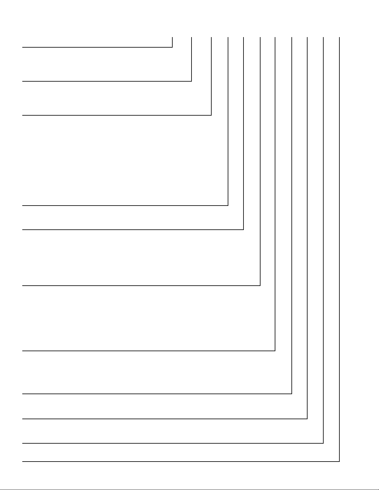
WHIRLPOOL MODEL NUMBER DESIGNATIONS
MODEL NUMBER M H 2 17 5 X S T 0
INTERNATIONAL SALES IND.
OR MARKETING CHANNEL
IF PRESENT
PRODUCT GROUP
G = WHIRLPOOL GOLD
M = MICROWAVE
PRODUCT IDENTIFICATION
B = BROWNER
C = CONVECTION
G = GRILL / CRISPER
H = OTR HOOD COMBO
K = KITS
M = GOLD CONVECTION
S = STIRRER FAN
T = TURNTABLE
MODEL VARIATIONS
0 - 9
CUBIC FEET
04 = .4 CU. FT. 09 = 0.9 CU. FT. 15 = 1.5 CU. FT.
06 = .6 CU. FT. 10 = 1.0 CU. FT. 16 = 1.6 CU. FT.
07 = .7 CU. FT. 12 = 1.2 CU. FT. 17 = 1.7 CU. FT.
08 = .8 CU. FT. 14 = 1.4 CU. FT.
FEATURE LEVEL
0 = 30” KIT (IF KIT)
2 = 22” KIT (IF KIT)
4 = 24” KIT (IF KIT)
5 = SENSORED MODEL
7 = 27” KIT (IF KIT)
FEATURE CODE
C = CSA APPROVED
S = CARRY IN WARRANTY (EFFECTIVE 02/96)
X = IN HOME WARRANTY (EFFECTIVE 02/96)
YEAR OF INTRODUCTION
S = 2006, T = 2007, V = 2008
COLOR CODE
B = BLACK, Q = WHITE, T = BISCUIT
ENGINEERING CHANGE (0, 1, 2, 3, ETC.)
1-5
Page 10
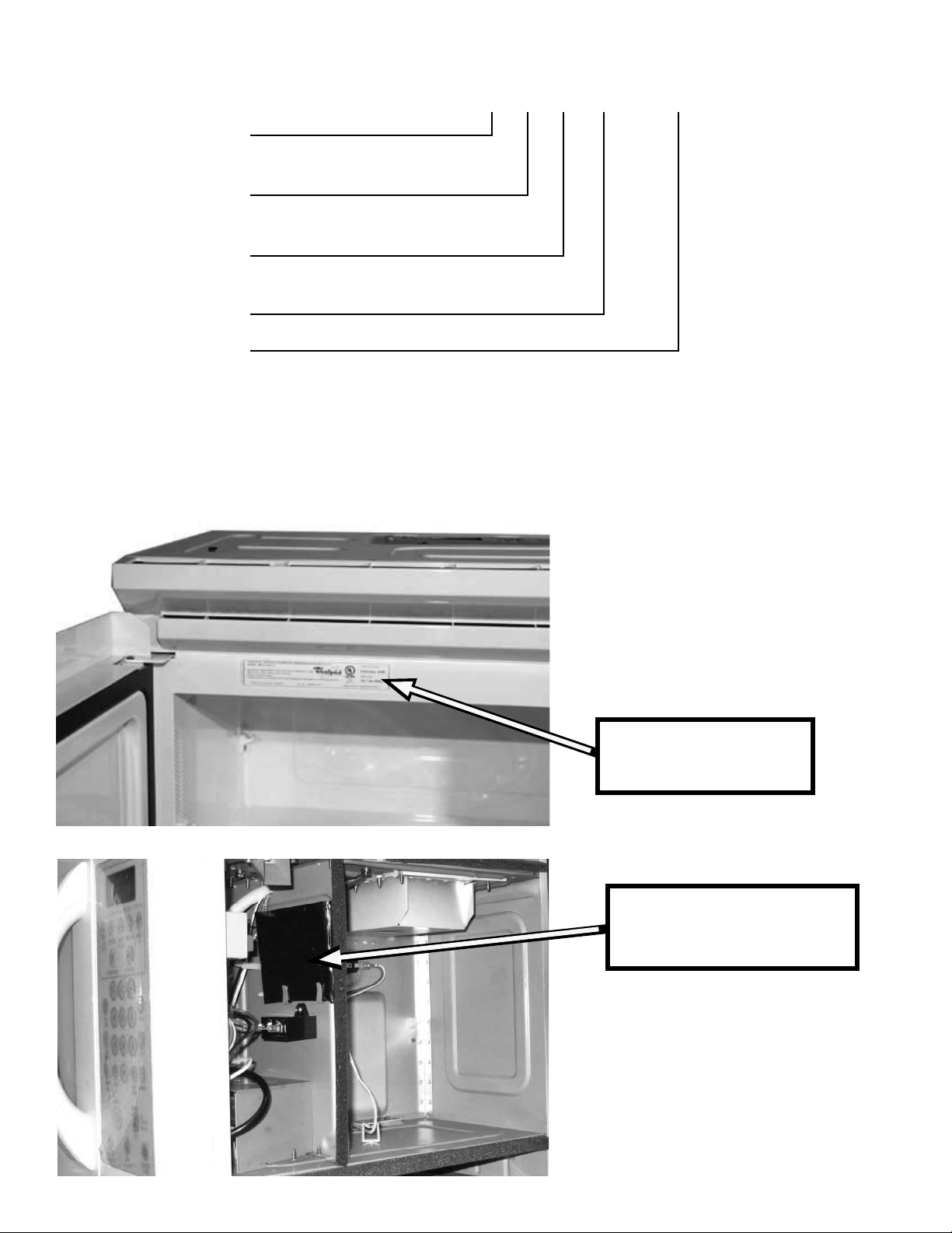
WHIRLPOOL SERIAL NUMBER DESIGNATIONS
SERIAL NUMBER TR T 06 10001
MANUFACTURING SITE
TR = Shunde
YEAR OF PRODUCTION
T = 2006
WEEK OF PRODUCTION
06 = 6th week of the year
PRODUCT SEQUENCE NUMBER
MODEL & SERIAL NUMBER LABEL AND
TECH SHEET LOCATIONS
Model & Serial
Number Location
1-6
Tech Sheet Location
(In black poly bag)
Page 11
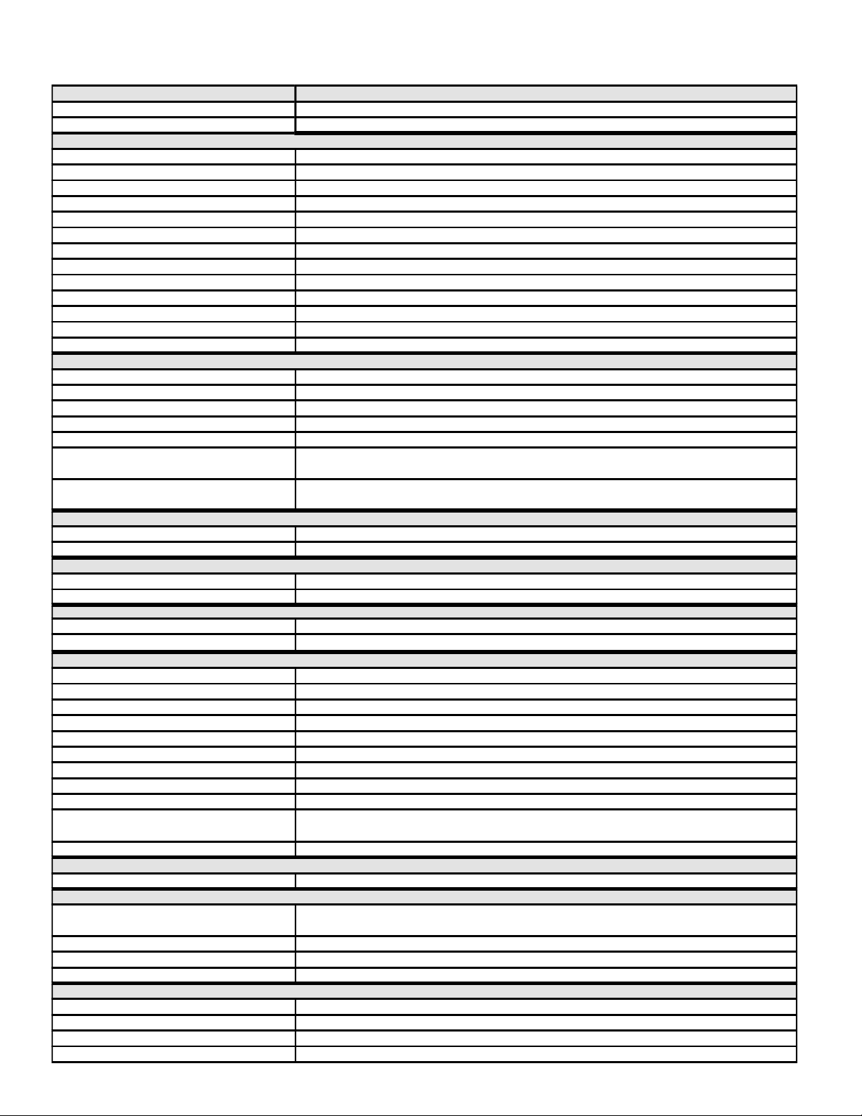
SPECIFICATIONS
MO DEL MH 2175XS
Fea tur e Level/Series SENSOR Cooking
Color s
White, Black, Biscuit and Stainless
CONTROL SYSTE M
Timer Electronic
Limits 99 Min. 99 Sec.
Operation TOUCH CONTROL, 30 Pads
Display Blue Green with scrolling text
Convection Cooking Cycles No
Keypad Disable / Child Lockout Mode Yes - Press "Cancel" Key for 3 Seconds
Cooktop Light Wattage One Incandescent 40 Watt bulb
Settings 3 levels (High, Night/Low, Off)
Fan Speed Indication "Low - Medium - High" -Scrolling Text
Power Failure Indication Yes - ' ' Displayed Flashing
Invalid Data Entry "BEEP"
Technical Error Indication "F-" With Error Number
Diagnostic System Yes
OVE N I NTERIOR F EATURES
Capacity 1.7 cu. ft.
Size W x H x D (inches)
21" W x 9 1/2" H x 14" D
Size W x H x D (mm)
535 x 240 x 355 mm
Cooking Power 1000 Watts (IEC-705 Rating)
Turn Table Yes, Sunken Flush
Cooling Fan Automatic - On if oven is operating,
Off if door open
Oven Light Automatic - Turns on when oven
door is open or oven is operating. (30 Watt)
DOOR F E ATURES
Handle/Latch Yes/Pull to open
Seals Two Stage (Capacitive and Reflective)
MICROWAVE SYSTE M
Distribution Top Feed w/ Stirrer
Magnetron One standard
SAFE TY F EATURES
Interlock
Three Door/Latch Operated (Primary, secondary and monitor)
Thermal Protectors
Four - 1 Magnetron, 1 Oven Cavity, 1 Hood, 1 Wave Guide
VENTILATION SYSTEM
Type Convertible Recirculation or Exhaust Vertical/Horizontal
Duct Outlet Size 3 1/4"H x 10"W
Recirculation CF M
112
Exhaust CFM
221
Touch Control 4 Speed
Exhaust Fan 'Auto ON - High Speed YES : 60° C, 140°F
Noise Level Recirculation (Acc. to IEC 704) 67dBA
Grease Filter Yes (2)-low cost
Charcoal Filter Yes (2)
Blower Type
Two Squirrel Cage Blower. Left fan wheel for hood airflow and cavity ventilation.
Right fan for cooling airflow
Shipped Recirculation mode
EXTERI OR F EATURES
Power Cord Length 3 Feet
OTHE R SP ECIF ICATIONS
Electrical 120V, Single Phase, 60 Hz
1800 Watts, For Use With 15 - 20 Amp Circuit
Domestic Use Only Yes
Agency Approvals FCC, DHHS, U.L. Listed, CSA
Approx. Net Weight - Lb 57 lbs.
LITE RATURE
Use & Care Guide 8205887
Installation Instructions 8206433
Warranty In Use & Care Guide
Tech Sheet 8205889
1-7
Page 12
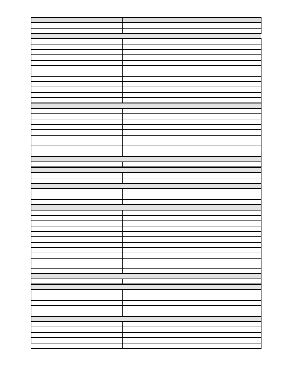
M O DEL M H 1160XSB/Q
Feature Level/Series Basic Non Sensor
Colors Black, White
CONTROL SYSTEM
Timer Electronic
Limits 99 Min. 99 Sec.
Operation TOUCH CONTROL, 25 Pads
Display Blue Green with scrolling text--Dual Language English and French
Convection Cooking Cycles No
Keypad Disable / Child Lockout Mode Yes - Press "Cancel" Key for 3 Seconds
Cooktop Light Wattage One Incandescent 40 Watt bulb
Fan Speed Indication "Low-Medium-High"-Scrolling Text
Power Failure Indication Yes - ':' Displayed Flashing
Invalid Data Entry "BEEP"
Technical Error Indication "F-" With Error Number
Diagnostic System Yes
OVEN INTERIOR FEATURES
Capacity 1.6 cu. ft.
Interior Dimensions W x H x D 21" W x 9 1/2" H x 14" D
Interior Dimensions W x H x D (mm) 535 x 240 x 355 mm
Cooking Power 950 Watts (IEC-705 Rating)
Turn Table Yes, Sunken Flush
Cooling Fan Automatic - On if oven is operating,
Off if door open
Oven Light Automatic - Turns on when oven
door is open or oven is operating. (30 Watts)
DOOR FEA TURES
Seals Two Stage (Capacitive and Reflective)
MICROWAVE SYSTEM
Distribution Top Feed w/o Stirrer
Magnetron One standard
SAFETY FEATURES
Interlock Three Door/Latch Operated
Primary, secondary and monitor
Thermal Protectors Four - 1 Magnetron, 1 Oven Cavity, 1 Hood, 1 Wave Guide
VENTIL A TION SYSTEM
Type Convertible Recirculation or Exhaust Vertical/Horizontal
Duct Outlet Size 3 1/4"H x 10"W
Recirculation CFM Out
112
Exhaust CFM Out
221
Touch Control 2 Speed
Exhaust Fan Auto ON - High Speed YES : 60° C, 140°F
Noise Level Recirculation (Acc. to IEC 704) Sound Power Level: 70 dB(A)
Grease Filter Yes (2)
Charcoal Filter Yes (1)
Blower Type/ Ventilation
Twin Squirrel Cage Blower: Left fan wheel for hood airflow and cavity ventilation.
Right fan for cooling airflow.
Shipped Recirculation mode
EXTERIOR FEA TURES
Power Cord Length 3 Feet
OTHER SPECIFICA TIONS
Electrical 120V, Single Phase, 60 Hz
1800 Watts, For Use With 15 - 20 Amp Circuit
Domestic Use Only Yes
Agency Approvals FCC, DHHS, UL, CUL
Approx. Net Weight - Lb 57 lbs.
LITERA TURE
Use & Care Guide 8205884
Installation Instructions 8205870
Warranty In Use & Care Guide
Tech Sheet 8205886
JobAid
8178573
1-8
Page 13
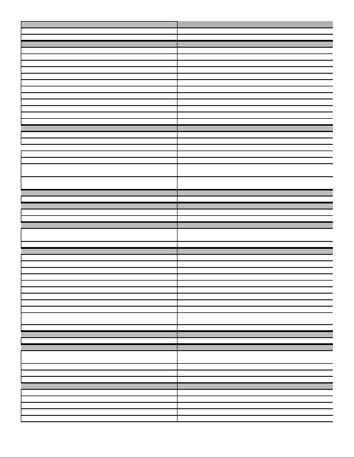
MH 1170XS TM H16XS
Basic Non Sensor Basic Non Sensor
Black, White, Biscuit and Stainless (B)Black, (Q)White, (D)Silver
Electronic Electronic
99 Min. 99 Sec. 99 Min. 99 Sec.
TOUCH CONTROL, TOUCH CONTROL,
Blue Green scrolling text--Dual Language English and French Blue Green with scrolling text--Dual Language English and French
No No
Yes - Press "Cancel" Key for 3 Seconds Yes - Press "Cancel" Key for 3 Seconds
One Incandescent 40 Watt bulb One Incandescent 40 Watt bulb
"Low-Medium-High"-Scrolling Text "Low-Medium-High"-Scrolling Text
Yes - ':' Displayed Flashing Yes - ':' Displayed Flashing
"RETRY"-Scrolling Text "RETRY"-Scrolling Text
"F-" With Error Number "F-" With Error Number
Yes Yes
1.7 cu. ft. 1.6 cu. ft.
21" W x 9 1/2" H x 14" D 21" W x 9 1/2" H x 14" D
535 x 240 x 355 mm 535 x 240 x 355 mm
1000 Watts (IEC-705 Rating) 1000 Watts (IEC-705 Rating)
Yes, Sunken Flush, Stoppable Yes, Sunken Flush
Automatic - On if oven is operating, Automatic - On if oven is operating,
Off if door open Off if door open
Automatic - Turns on when oven Automatic - Turns on when oven
door is open or oven is operating. (30 Watts) door is open or oven is operating. (30 Watts)
Two Stage (Capacitive and Reflective) Two Stage (Capacitive and Reflective)
Top Feed w/o Stirrer Top Feed w/o Stirrer
One standard One standard
Three Door/Latch Operated (Primary, secondary and monitor) Three Door/Latch Operated (Primary, secondary and monitor)
(Primary, secondary and monitor) (Primary, secondary and monitor)
Four - 1 Magnetron, 1 Oven Cavity, 1 Hood, 1 Wave Guide Four - 1 Magnetron, 1 Oven Cavity, 1 Hood, 1 Wave Guide
Convertible Recirculation or Exhaust Vertical/Horizontal Convertible Recirculation or Exhaust Vertical/Horizontal
3 1/4"H x 10"W 3 1/4"H x 10"W
112 112
221 221
2 Speed 2 Speed
YES : 60° C, 140°F YES : 60° C, 140°F
Sound Power Level: 70 dB(A) Sound Power Level: 70 dB(A)
Yes (2) Yes (2)
Yes (1) Yes (1)
Twin Squirrel Cage Blower: Left fan wheel for hood airflow and cavity ventilation.
Right fan for cooling airflow.
Twin Squirrel Cage Blower: Left fan wheel for hood airflow and cavity ventilation.
Right fan for cooling airflow.
Recirculation mode Recirculation mode
3 Feet 3 Feet
120V, Single Phase, 60 Hz 120V, Single Phase, 60 Hz
1800 Watts, For Use With 15 - 20 Amp Circuit 1800 Watts, For Use With 15 - 20 Amp Circuit
Yes Yes
FCC, DHHS, UL, CUL FCC, DHHS, UL, CUL
57 lbs. 57 lbs.
8205884 8205884
8205870
8205870
In Use & Care Guide In Use & Care Guide
8205880
8178573 8178573
1-9
Page 14
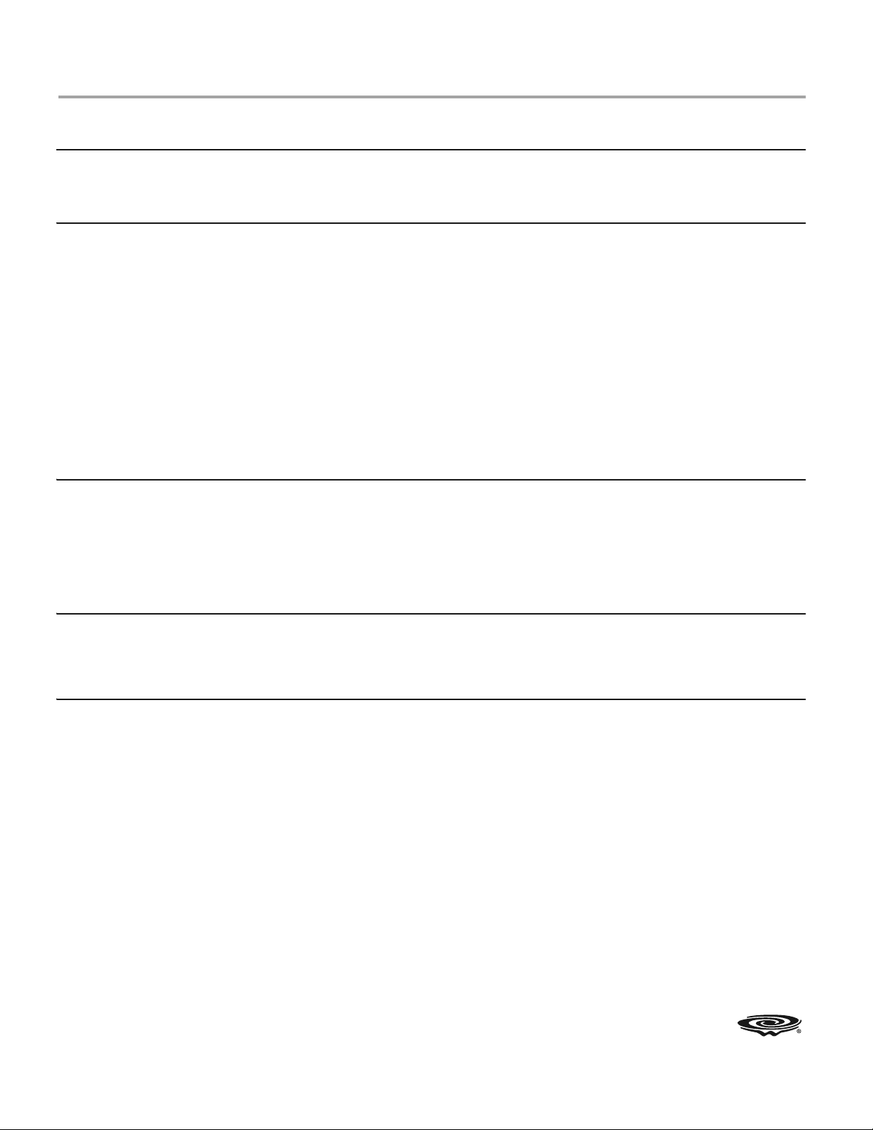
WHIRLPOOL MICROWAVE OVEN WARRANTY
WHIRLPOOL CORPORATION MAJOR APPLIANCE WARRANTY
ONE YEAR LIMITED WARRANTY
For one year from the date of purchase, when this major appliance is operated and maintained according to instructions attached to or
furnished with the product, Whirlpool Corporation or Whirlpool Canada LP (hereafter “Whirlpool”) will pay for FSP
®
replacement parts
and repair labor to correct defects in materials or workmanship. Service must be provided by a Whirlpool designated service company.
ITEMS WHIRLPOOL WILL NOT PAY FOR
1. Service calls to correct the installation of your major appliance, to instruct you how to use your major appliance, to replace or repair
house fuses or to correct house wiring or plumbing.
2. Service calls to repair or replace appliance light bulbs, air filters or water filters. Those consumable parts are excluded from warranty
coverage.
3. Repairs when your major appliance is used for other than normal, single-family household use.
4. Damage resulting from accident, alteration, misuse, abuse, fire, flood, acts of God, improper installation, installation not in
accordance with electrical or plumbing codes, or use of products not approved by Whirlpool.
5. Any food loss due to refrigerator or freezer product failures.
6. Replacement parts or repair labor costs for units operated outside the United States or Canada.
7. Pickup and delivery. This major appliance is designed to be repaired in the home.
8. Repairs to parts or systems resulting from unauthorized modifications made to the appliance.
9. Expenses for travel and transportation for product service in remote locations.
10. The removal and reinstallation of your appliance if it is installed in an inaccessible location or is not installed in accordance with
published installation instructions.
DISCLAIMER OF IMPLIED WARRANTIES; LIMITATION OF REMEDIES
CUSTOMER'S SOLE AND EXCLUSIVE REMEDY UNDER THIS LIMITED WARRANTY SHALL BE PRODUCT REPAIR AS PROVIDED
HEREIN. IMPLIED WARRANTIES, INCLUDING WARRANTIES OF MERCHANTABILITY OR FITNESS FOR A PARTICULAR PURPOSE,
ARE LIMITED TO ONE YEAR OR THE SHORTEST PERIOD ALLOWED BY LAW. WHIRLPOOL SHALL NOT BE LIABLE FOR
INCIDENTAL OR CONSEQUENTIAL DAMAGES. SOME STATES AND PROVINCES DO NOT ALLOW THE EXCLUSION OR LIMITATION
OF INCIDENTAL OR CONSEQUENTIAL DAMAGES, OR LIMITATIONS ON THE DURATION OF IMPLIED WARRANTIES OF
MERCHANTABILITY OR FITNESS, SO THESE EXCLUSIONS OR LIMITATIONS MAY NOT APPLY TO YOU. THIS WARRANTY GIVES
YOU SPECIFIC LEGAL RIGHTS AND YOU MAY ALSO HAVE OTHER RIGHTS, WHICH VARY FROM STATE TO STATE OR PROVINCE
TO PROVINCE.
Outside the 50 United States and Canada, this warranty does not apply. Contact your authorized Whirlpool dealer to determine if
another warranty applies.
If you need service, first see the “Troubleshooting” section of the Use & Care Guide. After checking “Troubleshooting,” additional help
can be found by checking the “Assistance or Service” section or by calling Whirlpool. In the U.S.A., call 1-800-253-1301. In Canada,
call 1-800-807-6777.
8/05
Keep this book and your sales slip together for future
reference. You must provide proof of purchase or installation
date for in-warranty service.
Write down the following information about your major appliance
to better help you obtain assistance or service if you ever need it.
You will need to know your complete model number and serial
number. You can find this information on the model and serial
number label located on the product.
Dealer name ____________________________________________________
Address ________________________________________________________
Phone number __________________________________________________
Model number __________________________________________________
Serial number __________________________________________________
Purchase date __________________________________________________
8205884
© 2005 Whirlpool Corporation.
.A.S.U,looplrihWfokramedarTMT/kramedarTderetsigeR®.devresersthgirllA
4619-652-68351
11/05
Printed in China
1-10
Page 15

INSTALLATION INFORMATION
HOOD FAN MOTOR MOUNTING POSITIONS
RECIRCULATING AIR
REAR VENTED AIR
Airow towards front of unit.
Note: this is the way the
unit is shipped.
Airow towards rear of unit. Unplug
wire, turn fan motor over, and plug
wire back into the quick disconnect
socket over the top of the fan motor.
TOP VENTED AIR
Airow towards top of unit.
2-1
Page 16

---- NOTES ----
2-2
Page 17
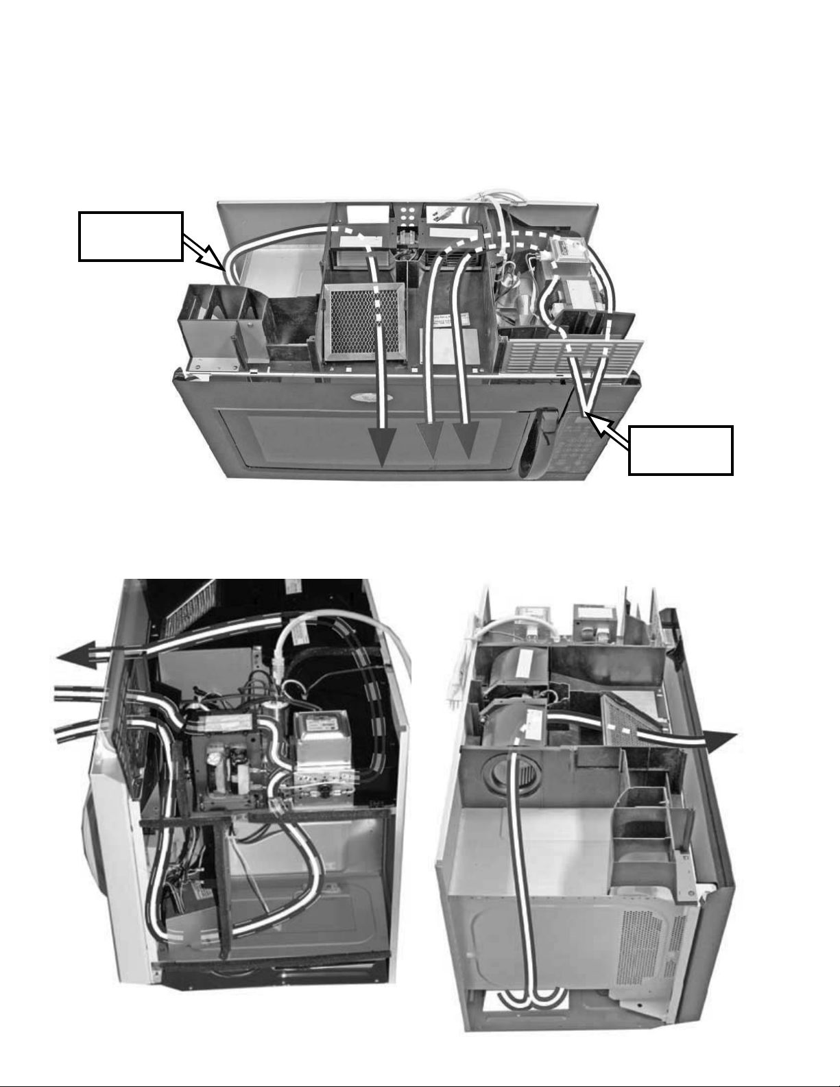
THEORY OF OPERATION
AIRFLOW PATHS
The microwave uses the exhaust blower motor to remove vapors from the cooking area below the
unit, it also circulates air within the unit to assist cooking performance and cool the operating components.
Cooktop
Venting
Component
cooling
This process is accomplished by using one side
of the blower motor assembly to pull ambient air
into the unit to cool the working components,
and the remaining side of the blower for exhausting steam and cooking odors.
3-1
Page 18
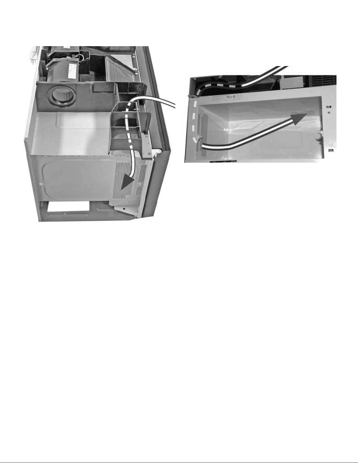
Air is circulated in the unit to assist cooking
performance.
The motor operates at two speeds--low speed all
of the time and high speed during sensor-cooking
modes.
3-2
Page 19
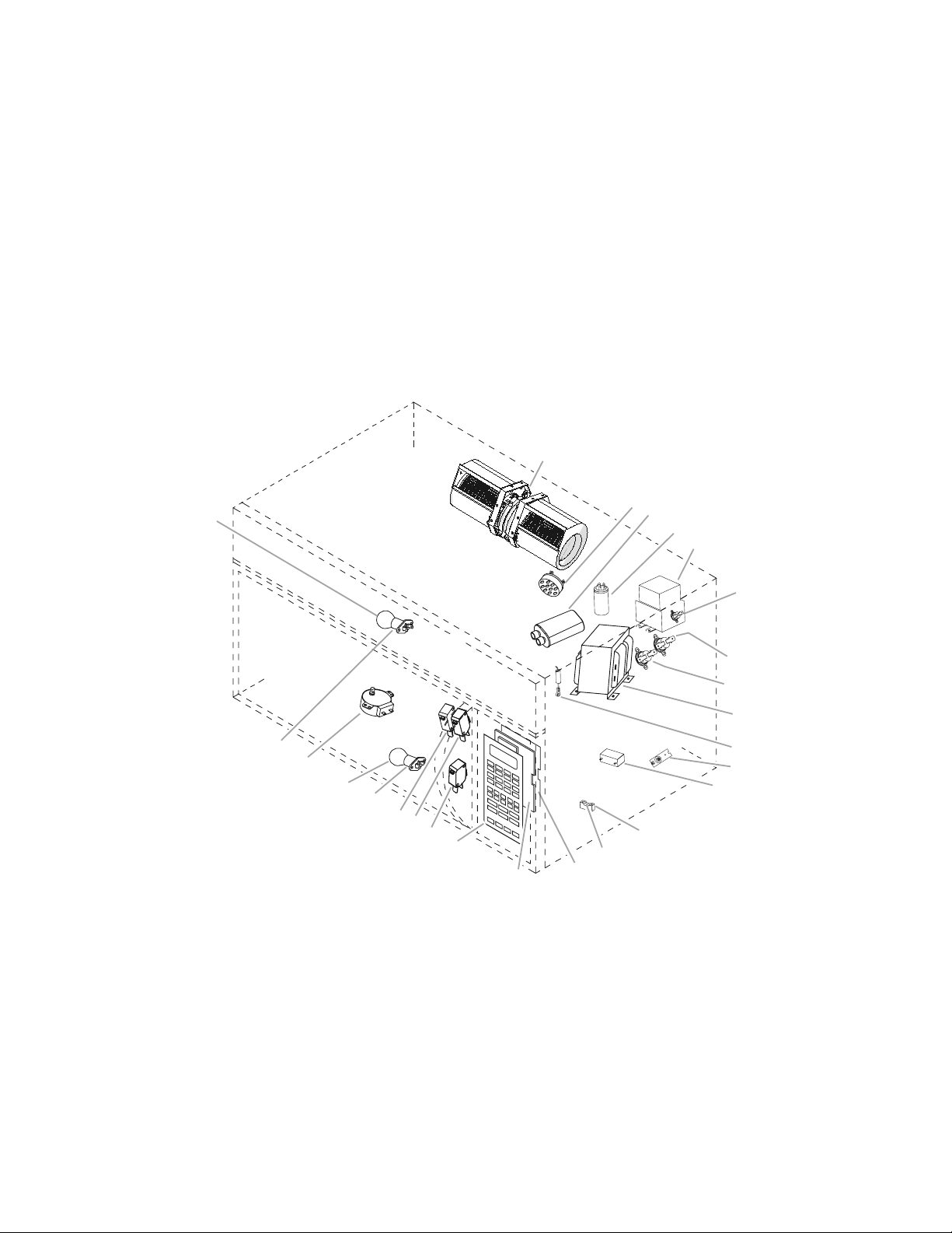
COMPONENT ACCESS
PartsLayout
(nottoscale)
A. Hood fan motor assembly
B. Humidity sensor
C. H.V. capacitor
D. AC line filter
E. Magnetron
F. Magnetron thermostat—opens at 257ºF
(125ºC), closes at 185ºF (85ºC)
G. Cavity thermostat 1—opens at 257ºF
(125ºC), closes at -31ºF (-35ºC)
H. Cavity thermostat 2—opens at 257ºF
(125ºC), closes at -31ºF (-35ºC)
I. H.V. transformer
J. H.V. diode
K. NTC thermistor
L. Motor capacitor
M. Line fuse
N. Fuse holder
O. Power display
P. Electronic control
Q. Touch panel
R. Secondary interlock switch
S. Monitor interlock switch
T. Primary interlock switch
U. Lamp holders
V. Hood (cooktop) lamp
W. Turntable motor
X. Cavity lamp
A
B
C
D
E
F
G
H
I
J
K
L
M
N
O
P
Q
R
S
U
U
T
W
V
3
5
5
1
P
5
X
This section instructs you on how to service each component inside the Model MH2175XS
Microwave Oven Hood Combination. The components and their locations are shown below.
COMPONENT LOCATIONS
4-1
Page 20
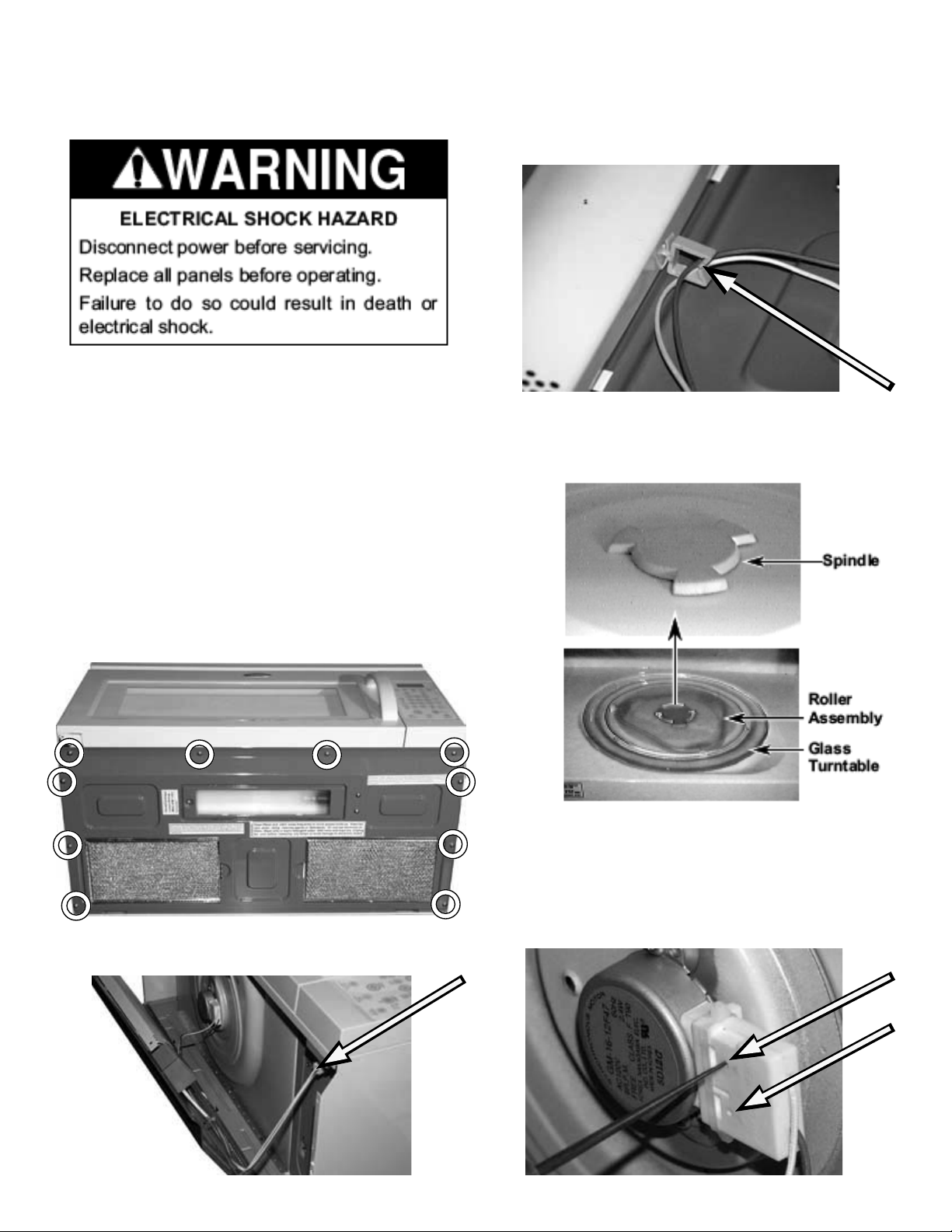
REMOVING THE TURNTABLE MOTOR &
HOOD (COOKTOP) LAMP ASSEMBLY
IMPORTANT: When you work on the microwave
oven, be careful when handling the sheet metal
parts. Sharp edges may be present, and you
can cut yourself if you are not careful.
1. Unplug microwave oven or disconnect power.
4. Remove the wire from the wire clip towards the
middle of the bottom cover.
5. To remove the turntable motor:
a) Remove the glass turntable, roller assembly,
and spindle from inside the oven cavity.
2. Remove the ten screws from the bottom
cover and partially lower the top edge
of the cover so you can access the component
wiring below it.
3. Disconnect the wire connector at the right side.
b) There are two small holes on the connector.
Lower the bottom cover just far enough to get
a sharp tool with the right size (diameter less
than 2mm) to press into the two access holes
one by one and release the connector.
4-2
Page 21
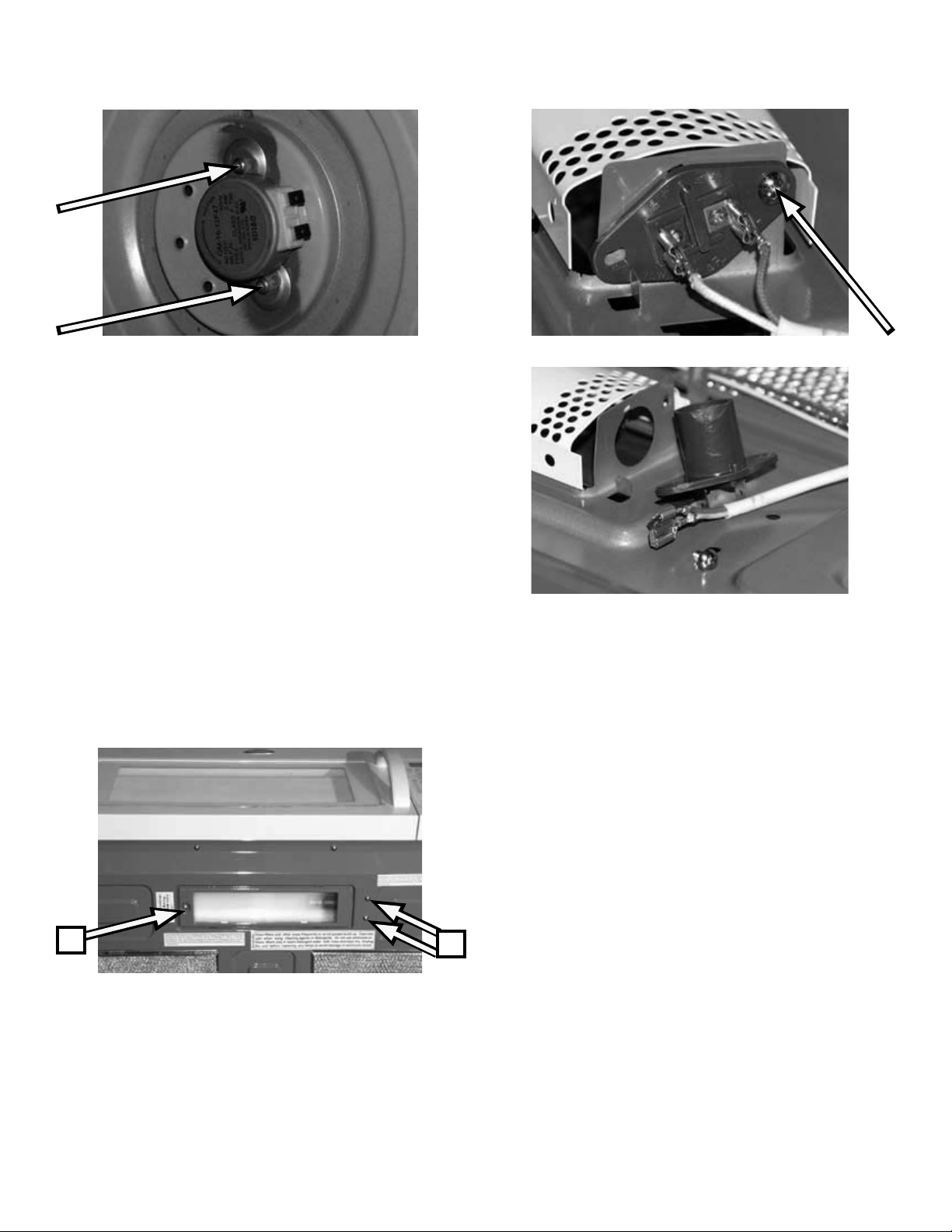
c) Remove the two screws from the turntable
motor and remove the motor.
NOTE: When reassembling the wire connector onto the turntable motor, make sure the
holes of the connector are facing away from
the bottom of the unit, outward toward you.
6. To remove the cooktop lamp assembly:
a) Remove the one screw to the left of the
lamp housing that secures the lamp cover to
the bottom of the unit.
f) Remove one screw to remove the lamp
socket.
b) Remove the lamp from the socket.
c) Remove the two screws to the right of the
lamp housing that secure the lamp xture
electrical box cover to the inside of the bottom
cover.
a
d) Remove the bottom cover from the unit.
(see page 4-2 steps 1 thru 4)
c
e) Remove the electrical box cover to expose
the lamp socket, wire connectors and one
screw.
4-3
Page 22
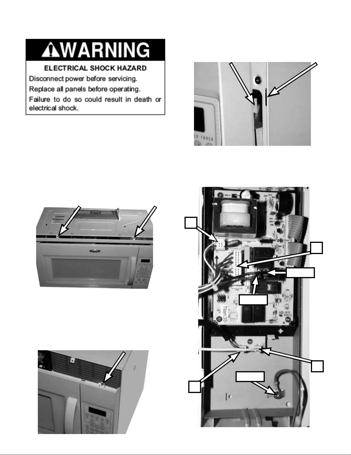
REMOVING THE CONTROL PANEL & CONTROL BOARD
5. Push the panel up to release the tabs from the
slots. Pull the panel away from the microwave
unit to gain access to the back side of it.
IMPORTANT: When you work on the microwave
oven, be careful when handling the sheet metal
parts. Sharp edges may be present, and you
can cut yourself if you are not careful.
6. Disconnect the seven wire connectors from the
1. Unplug microwave oven or disconnect power.
2. Remove the two screws from the top of the
grille.
control board.
3. Pull the top of the air grille forward, lift the bottom tabs from the slots, and remove the grille.
4. Remove the screw from the top of the control
panel.
P3
P2
Black
Brown
P4
Ground
P1
4-4
Page 23
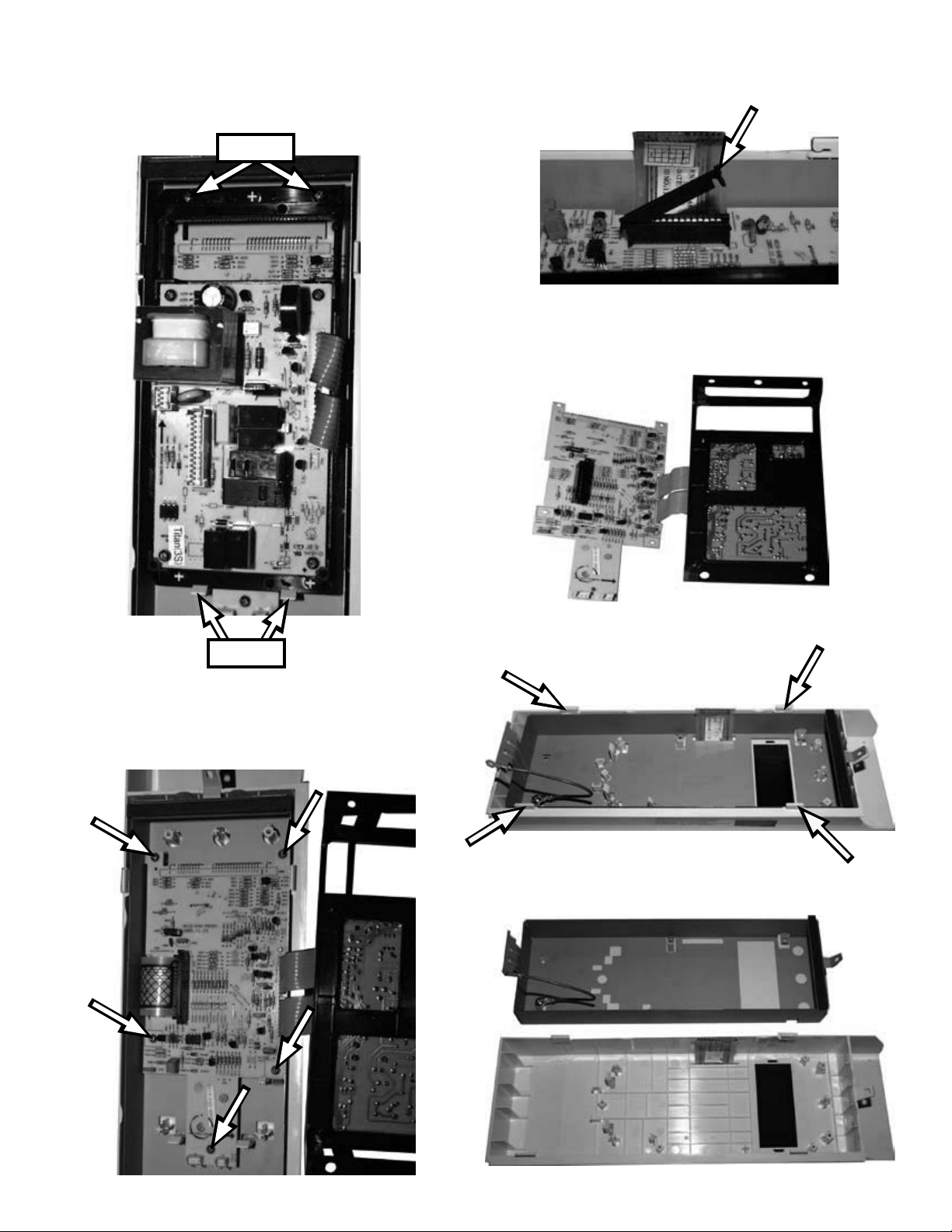
7. To remove the microcomputer board:
a) Remove 2 screws at the top and release
2 tabs at the bottom to be able to lift the top
board.
Screws
c) Press in on the locking tab end of the arm
and lift the arm to release the touch panel ribbon cable.
d) You can now remove the microcomputer
board assembly.
Tabs
b) Remove 5 screws from the bottom board to
release it from the touch panel assembly.
e) To remove the microcomputer board mounting bracket release 4 tabs.
f) Pull the bracket out of the touch panel assembly.
4-5
Page 24
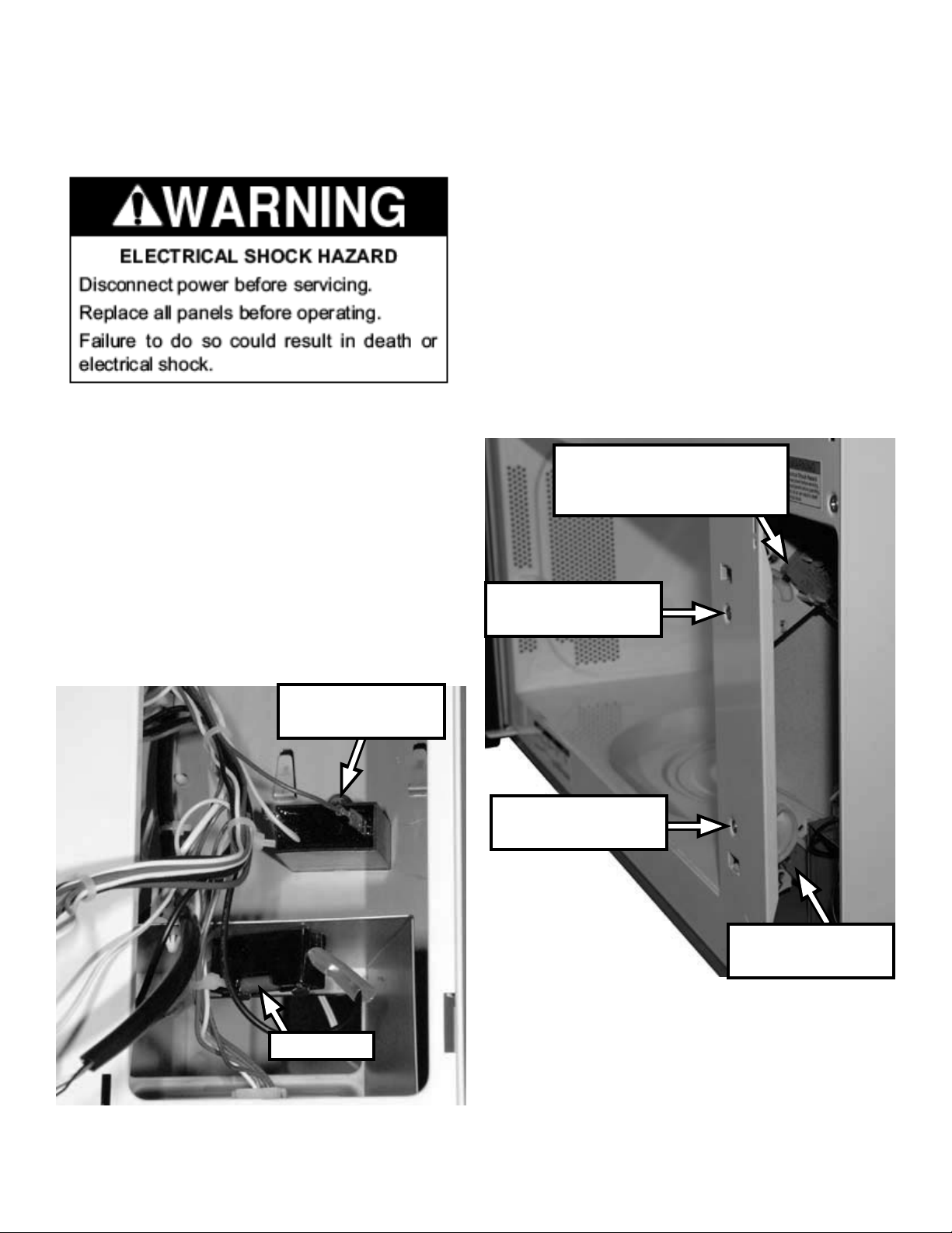
REMOVING THE MOTOR CAPACITOR AND LINE FUSE
REMOVING THE DOOR SWITCHES
IMPORTANT: When you work on the microwave
oven, be careful when handling the sheet metal
parts. Sharp edges may be present, and you
can cut yourself if you are not careful.
To remove the door switches:
1. Unplug microwave oven or disconnect power.
2. Remove the control panel (see page 4-4).
3. Open the microwave oven door.
4. The Primary interlock switch and Monitor interlock switch are attached to a mounting bracket
at the top.
Primary interlock switch
and Monitor interlock
switch assembly
1. Unplug microwave oven or disconnect power.
2. Remove the control panel (see page 4-4).
3. To remove the motor capacitor, remove one
screw.
Motor Capacitor
Screw
Top switch
assembly screw
Bottom switch
assembly screw
Secondary inter-
lock switch
Line Fuse
4. To remove the line fuse, pull the fuse out of the
fuse holder.
5. The secondary interlock switch is attached to a
mounting bracket at the bottom.
4-6
Page 25
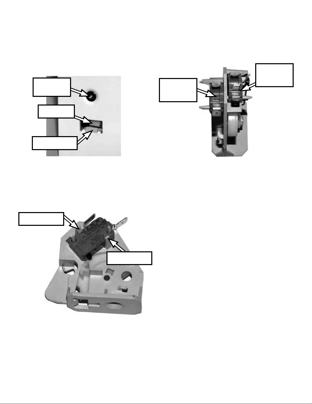
6. To remove a switch assembly, remove the
mounting screw from the front panel of the
microwave for the desired assembly.
7. Use a at blade screwdriver to push the latch
arm back just far enough to release the mounting tab and remove the assembly from the unit.
Mounting
screw
Latch arm
Mounting tab
8. Disconnect the wire connectors from the terminals.
10. The Primary interlock switch and Monitor
interlock switch are located on opposite sides
of their mounting bracket. The Primary interlock switch can be removed from the mounting
bracket in the same manner as shown above
for the Monitor interlock switch.
Primary
Interlock
Monitor
Interlock
Switch
Switch
9. To remove the monitor interlock switch from
the mounting bracket, press the locking tabs
away from the switch and slide the switch up
off the mounting posts.
Locking tab
Locking tab
4-7
Page 26
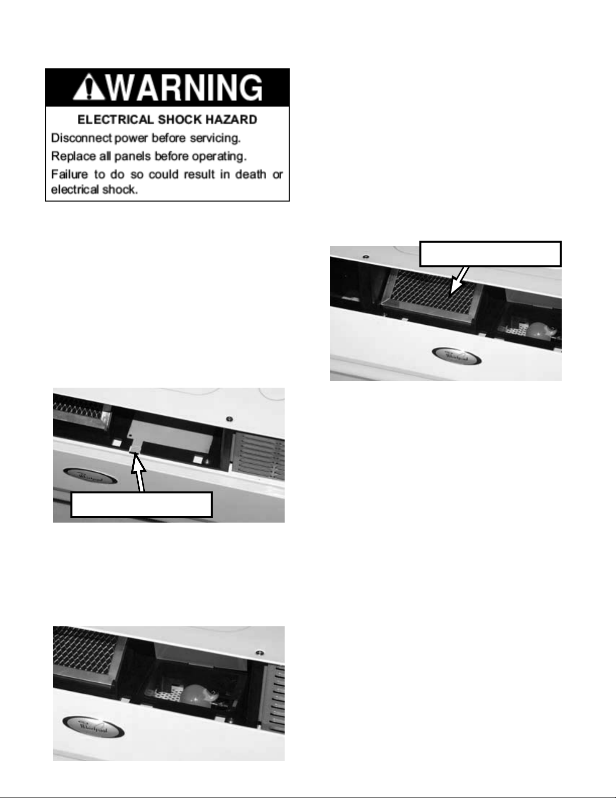
REMOVING THE OVEN CAVITY LAMP AND CHARCOAL FILTER
To remove the charcoal lter:
1. Unplug microwave oven or disconnect power.
2. Remove the air grille (see page 4-4).
3. Lift the charcoal lter from the mounting frame
and pull it out of the microwave unit.
4. Replace the charcoal lter with the correct
IMPORTANT: When you work on the microwave
oven, be careful when handling the sheet metal
parts. Sharp edges may be present, and you
can cut yourself if you are not careful.
1. Unplug microwave oven or disconnect power.
2. Remove the air grille (see page 4-4).
replacement lter.
Charcoal lter
3. To change the oven cavity lamp, lift the tab on
the cover to access the lamp.
Lift tab to access lamp
4. Unscrew the lamp from the socket. There will
be a dab of silicone that is intended to keep
the bulb from loosening in the socket during
shipping. Be sure to clean off any loose silicone from the socket before installing a new
lamp.
4-8
Page 27
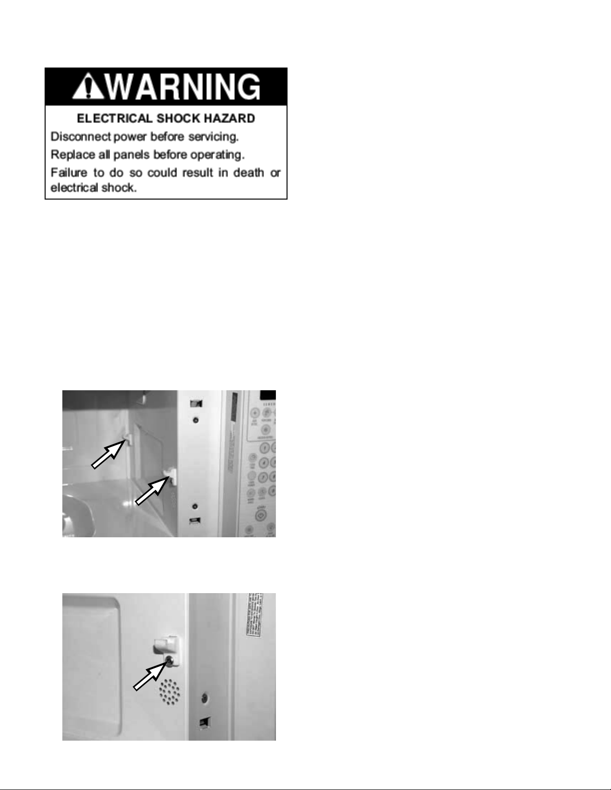
REMOVING THE OVEN RACK RETAINERS
IMPORTANT: When you work on the microwave
oven, be careful when handling the sheet metal
parts. Sharp edges may be present, and you
can cut yourself if you are not careful.
1. Unplug microwave oven or disconnect power.
2. Open the microwave oven door.
3. Locate the four oven rack retainers, two on
each side of the oven interior.
4. Remove the one screw that attaches each rack
retainer to the wall of the microwave oven.
4-9
Page 28
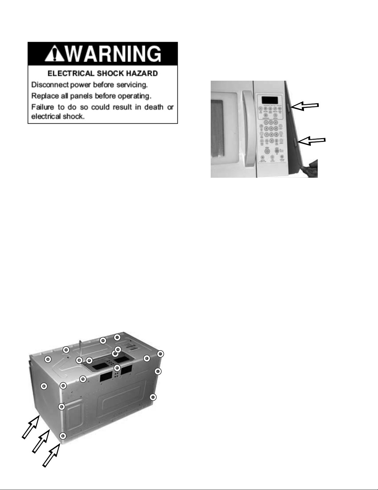
REMOVING THE OUTER CABINET
IMPORTANT: When you work on the microwave
oven, be careful when handling the sheet metal
parts. Sharp edges may be present, and you
can cut yourself if you are not careful.
1. Unplug microwave oven or disconnect power.
2. Remove the air grille (see page 4-4).
7. After removing all the screws, pull each side
out and push it back from the front corners of
the unit to release the tabs on the inside front
edge of the cabinet.
8. The cabinet may now be completely removed
from the unit.
3. Remove the 8 screws visible on the top of the
microwave unit.
4. Remove the 1 screw visible on the side.
5. Remove the 9 screws around the edge of the
back panel.
6. Remove the 3 screws on each end of the bottom panel (not shown).
9. CAUTION: Discharge the high-voltage capacitor with a 20,000 Ohm resistor to chassis
ground.
4-10
Page 29
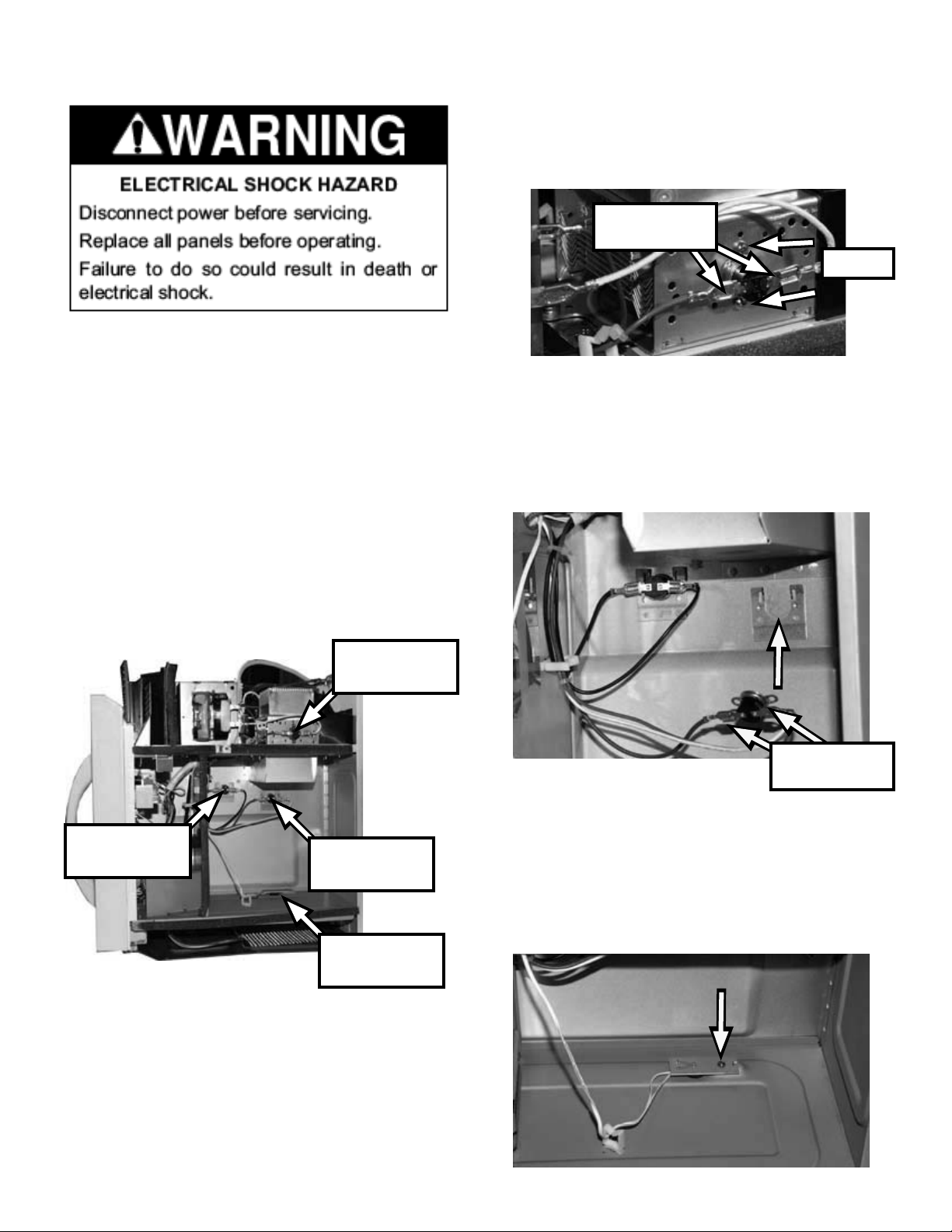
REMOVING THE THERMOSTATS AND THERMISTOR
IMPORTANT: When you work on the microwave
oven, be careful when handling the sheet metal
parts. Sharp edges may be present, and you
can cut yourself if you are not careful.
To remove the magnetron thermostat:
1. Remove 2 screws and disconnect the wire
connectors.
Wire
Connectors
Screws
To remove the Cavity thermostats:
1. Unplug microwave oven or disconnect power.
2. Remove the outer cabinet (see page 4-10).
3. CAUTION: Discharge the high-voltage capacitor with a 20,000 Ohm resistor to chassis
ground.
Magnetron
thermostat
Cavity
thermostat 2
Cavity
thermostat 1
1. Slide the thermostat up and out from behind
the mounting bracket. Remove the wire connectors.
Wire
Connectors
To remove the NTC thermistor (base thermis-
tor):
1. Remove one screw and remove the connection
at P4 of the microcomputer board (see illustration on page 4-4).
NTC
thermistor
4-11
Page 30
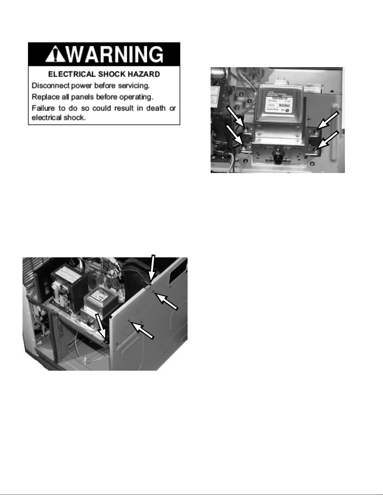
REMOVING THE MAGNETRON
IMPORTANT: When you work on the microwave
oven, be careful when handling the sheet metal
parts. Sharp edges may be present, and you
can cut yourself if you are not careful.
1. Unplug microwave oven or disconnect power.
2. Remove the outer cabinet (see page 4-10).
6. Remove the four T-20 Torx® screws that secure the magnetron to the unit and remove the
magnetron.
3. CAUTION: Discharge the high-voltage capacitor with a 20,000 Ohm resistor to chassis
ground.
4. Remove 3 screws that secure the air shroud
and 1 screw that secures the ground wire. Lift
the air shroud up to expose two of the four
screws that secure the magnetron to the unit.
5. Remove 2 wire connectors from the thermostat
and 2 wire connectors from the magnetron
terminals.
4-12
Page 31
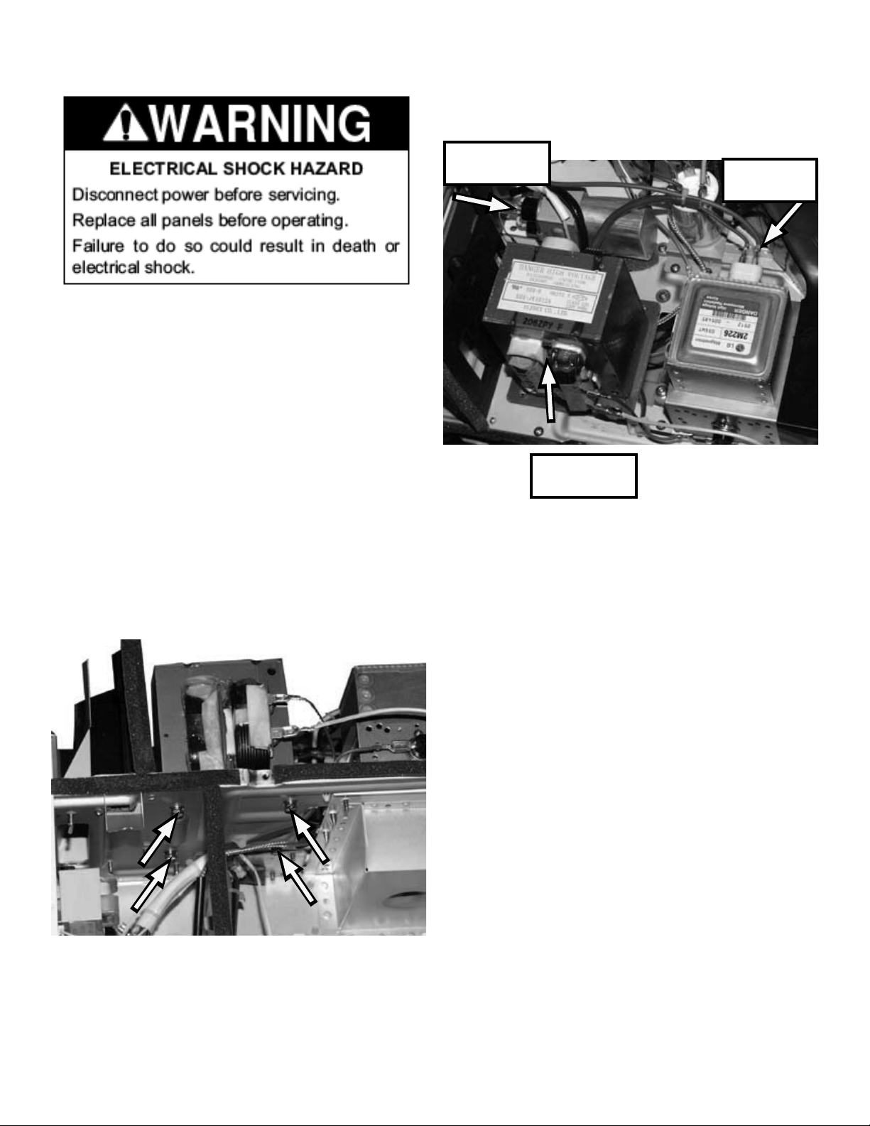
REMOVING THE HIGH-VOLTAGE TRANSFORMER
IMPORTANT: When you work on the microwave
oven, be careful when handling the sheet metal
parts. Sharp edges may be present, and you
can cut yourself if you are not careful.
1. Unplug microwave oven or disconnect power.
5. Remove the 2 wire connectors on the front, 1
wire connector from the magnetron and 2 wire
connectors from the capacitor.
2 Wire
Connectors
1 Wire
Connector
2. Remove the outer cabinet (see page 4-10).
3. CAUTION: Discharge the high-voltage capacitor with a 20,000 Ohm resistor to chassis
ground.
4. Remove the 4 screws from below the transformer that secure it to the microwave unit.
2 Wire
Connectors
4-13
Page 32
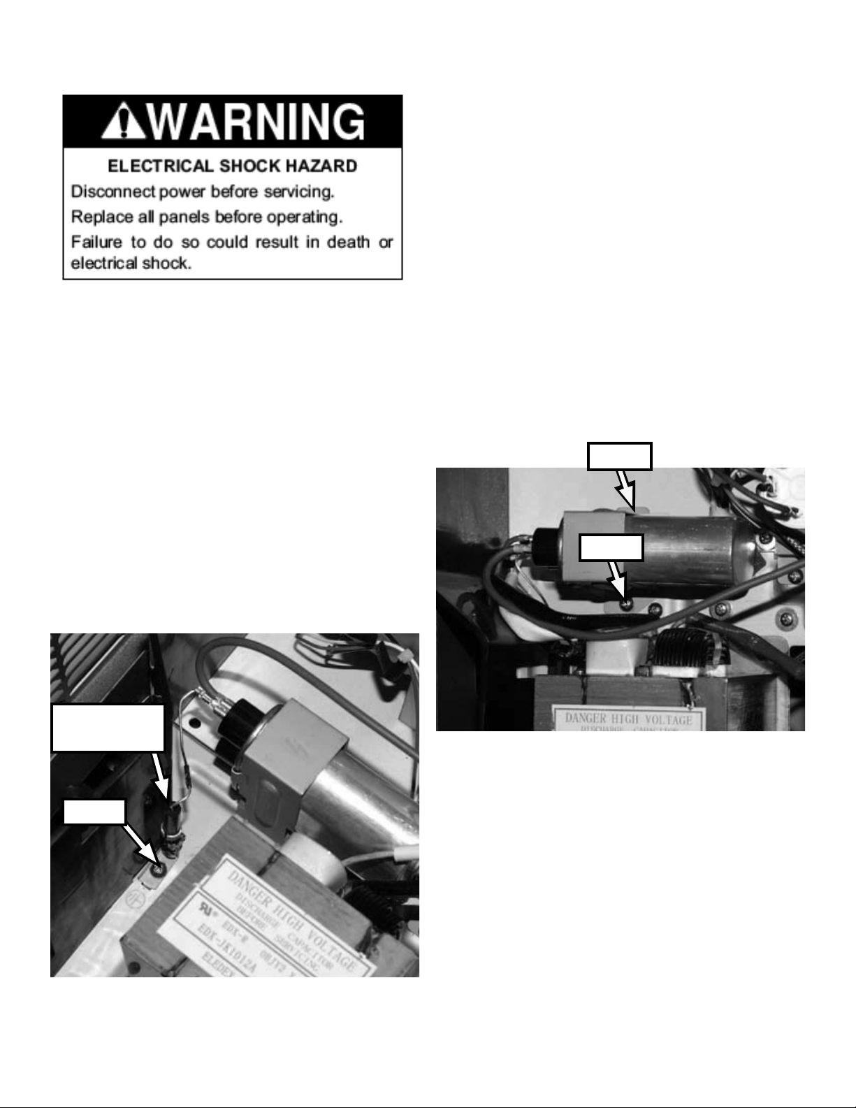
REMOVING THE HIGH-VOLTAGE DIODE AND CAPACITOR
To remove the High-Voltage Capacitor:
1. Unplug microwave oven or disconnect power.
2. Remove the outer cabinet (see page 4-10).
3. CAUTION: Discharge the high-voltage capacitor with a 20,000 Ohm resistor to chassis
ground.
IMPORTANT: When you work on the microwave
oven, be careful when handling the sheet metal
parts. Sharp edges may be present, and you
can cut yourself if you are not careful.
1. Unplug microwave oven or disconnect power.
2. Remove the outer cabinet (see page 4-10).
3. CAUTION: Discharge the high-voltage capacitor with a 20,000 Ohm resistor to chassis
ground.
4. Remove one screw to remove the diode. Disconnect one wire connector from the capacitor.
4. Remove one screw and slide the tab out from
the slot in the unit.
5. Disconnect the wire connectors and remove
the capacitor from the unit.
Tab
Screw
High Voltage
Diode
Screw
4-14
Page 33
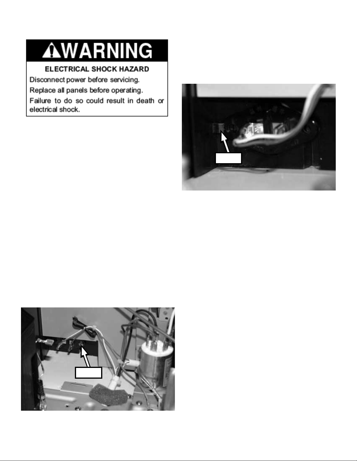
REMOVING THE OVEN CAVITY LAMP SOCKET
IMPORTANT: When you work on the microwave
oven, be careful when handling the sheet metal
parts. Sharp edges may be present, and you
can cut yourself if you are not careful.
1. Unplug microwave oven or disconnect power.
2. Remove the outer cabinet (see page 4-10).
7. Twist the lamp socket to release it from the one
tab on the left side.
8. Remove the two wire connectors and remove
the lamp socket from the unit.
Tab
3. CAUTION: Discharge the high-voltage ca-
pacitor with a 20,000 Ohm resistor to chassis
ground.
4. Remove the oven cavity lamp (see page 4-8).
5. Remove the capacitor (see previous page).
6. Remove one screw that secures the oven cavity lamp socket to the unit.
Screw
4-15
Page 34
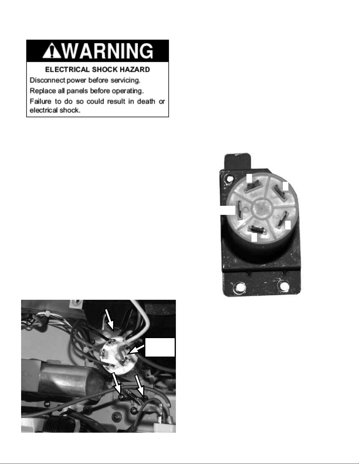
REMOVING THE AC LINE FILTER
6. When reinstalling the wire connectors to the
AC line lter, install the following wires to the
following connection spades:
1. Black AC line in
2. White AC line in
3. Black
IMPORTANT: When you work on the microwave
oven, be careful when handling the sheet metal
parts. Sharp edges may be present, and you
can cut yourself if you are not careful.
1. Unplug microwave oven or disconnect power.
2. Remove the outer cabinet (see page 4-10).
3. CAUTION: Discharge the high-voltage capacitor with a 20,000 Ohm resistor to chassis
ground.
4. Remove 3 screws that secure the AC line lter
to the unit. Slide the AC line lter and bracket
out from under the tab to remove it.
5. Disconnect the 5 wire connectors from the AC
line lter.
4. Blue
Green Ground
3
1
Ground
2
4
AC Line
Filter
4-16
Page 35
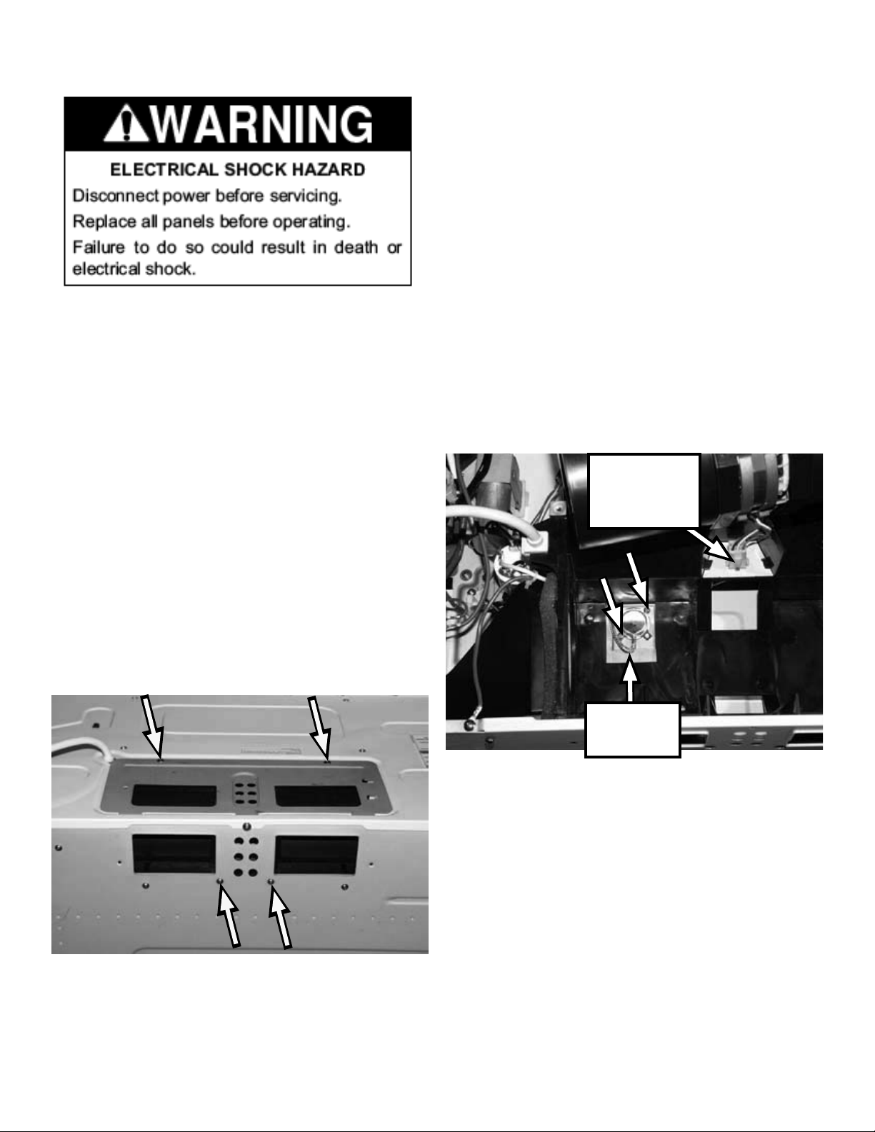
REMOVING THE HOOD FAN MOTOR AND HUMIDITY SENSOR
To remove the humidity sensor:
1. Unplug microwave oven or disconnect power.
2. Remove the outer cabinet (see page 4-10).
3. CAUTION: Discharge the high-voltage capacitor with a 20,000 Ohm resistor to chassis
ground.
IMPORTANT: When you work on the microwave
oven, be careful when handling the sheet metal
parts. Sharp edges may be present, and you
can cut yourself if you are not careful.
1. Unplug microwave oven or disconnect power.
2. Remove 2 screws from the top of the microwave oven that secure the cover plate to the
outer cabinet. Lift the front of the cover plate
and pull the tabs out of the slots at the back of
the unit.
3. Remove 2 screws from the back of the unit that
secure the hood fan motor assembly to the
unit.
4. Remove the hood fan motor. (See left column)
5. Remove the 2 screws that secure the Humidity
sensor to the unit. Disconnect the wire connector at P1 on the microcomputer board (see
illustration on page 4-4).
Hood fan
motor wiring
connector
4. Pull the hood fan motor assembly up and out
of the top of the unit. Disconnect the wiring
connector to remove the assembly.
Humidity
Sensor
4-17
Page 36
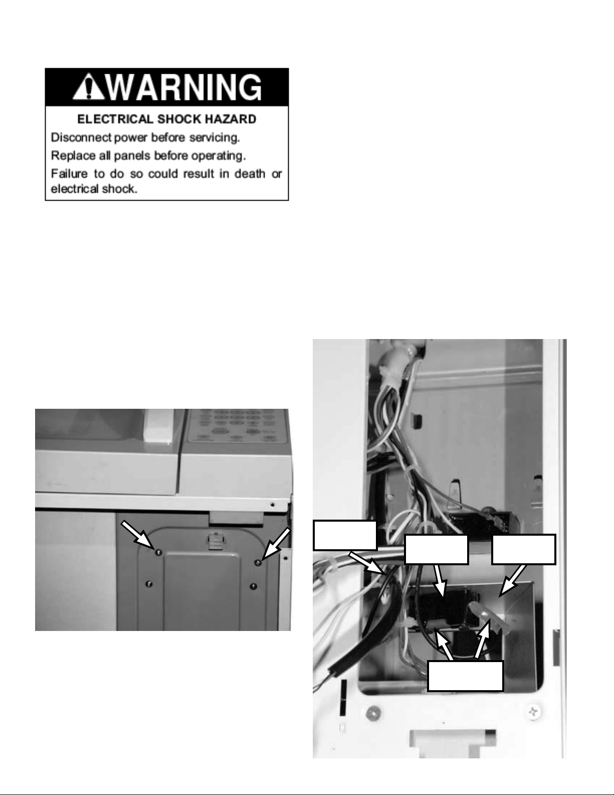
REMOVING THE FUSE HOLDER & MOUNTING BRACKET
4. Remove the control panel (see page 4-4, steps
2 - 5).
5. Remove the wires from the retainer on the top
of the fuse holder mounting bracket.
6. Remove the 2 wire connectors from the fuse
holder.
IMPORTANT: When you work on the microwave
oven, be careful when handling the sheet metal
parts. Sharp edges may be present, and you
can cut yourself if you are not careful.
1. Unplug microwave oven or disconnect power.
2. Remove the bottom cover (see page 4-2, steps
1-3).
3. Remove the 2 screws near the front right corner of the bottom of the unit.
7. Pull the assembly out of the microwave unit.
8. Remove the fuse from the holder.
9. Remove 1 screw in the bottom of the fuse
holder to remove the holder (not shown in
photo. Only visible when fuse is removed).
4-18
Wire
Retainer
Fuse
holder
2 Wire
connectors
Mounting
bracket
Page 37
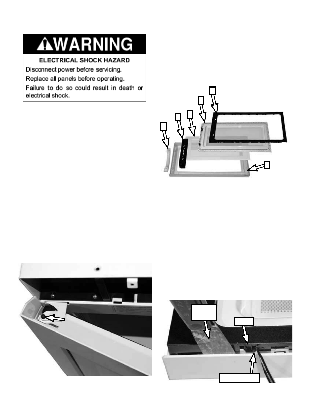
REMOVING THE DOOR AND DOOR DISASSEMBLY
Components of the MHC door (in order of
removal.):
1. Choke Seal
2. Inner Door
3. Handle
4. Door Bracket
5. Outer Glass
6. Door Frame
1
2
IMPORTANT: When you work on the microwave
oven, be careful when handling the sheet metal
parts. Sharp edges may be present, and you
can cut yourself if you are not careful.
1. Unplug microwave oven or disconnect power.
2. Remove the air grille (see page 4-4,
steps 2 & 3).
3. Remove the 1 T-10 Torx® screw from the top
hinge of the door.
4. Lift the door up and off the other hinge to remove the door.
5. Place the door face down on a protective surface. (All removal procedures assume the door
is face down with the handle to the left.)
5
4
3
6
Choke seal removal:
1. There are 4 tabs on the top edge, 3 tabs on
each side and 5 tabs on the bottom edge.
2. Use a putty knife to open the gap between the
door frame and the choke seal.
3. Locate each tab and use a at blade screwdriver to gently lift the choke seal and release
each tab. Place the screwdriver in the slot directly beside each tab and lift from there.
4. Only lift enough to release each tab all the way
around the choke seal to avoid bending and possibly breaking the choke seal.
Putty
Knife
Tab
Screwdriver
4-19
Page 38
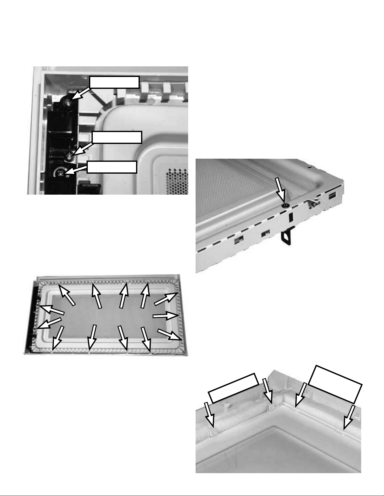
Inner door removal: This shows the screw loca-
tions for each labeled component at the top of
the door bracket. The same screws are at the
bottom of the bracket, in reverse order.
Door bracket
Inner door
Handle
2. Beginning at the bottom left corner, work your
way across the bottom edge to release 4 tabs.
Release 3 tabs on the right edge and 2 tabs on
the left edge.
Door bracket removal:
1. Remove two screws that secure the door
bracket to the door frame. Refer to the photo in
the left column for screw location.
Door Latch Removal:
1. After removing the Inner door, turn it over.
2. Each door latch is secured with one screw.
Remove the screw and slide the latch out of the
slot in the inner door.
3. Gently lift the inner door from the bottom edge
to release the 4 clips along the top edge.
Handle removal:
1. Remove two screws from the door bracket that
secure the handle to the front of the door. Refer
to the photo at the top of this column for screw
location.
2. The handle can be replaced without regard for
orientation of top and bottom.
Outer glass removal:
1. Press the 5 tabs at the top edge of the outer
glass that secure it to the door frame.
2. Lift the glass at the top left corner just enough
to slide the glass to the left and up from under the
tabs on the right and bottom edges.
Slide out
from under
Press tabs
4-20
Page 39
COMPONENT TESTING
Important
Before testing any of the components, perform
the following checks:
• Unplug microwave oven or disconnect power.
• Remove the lead wires from the related component before conducting any of the following
tests.
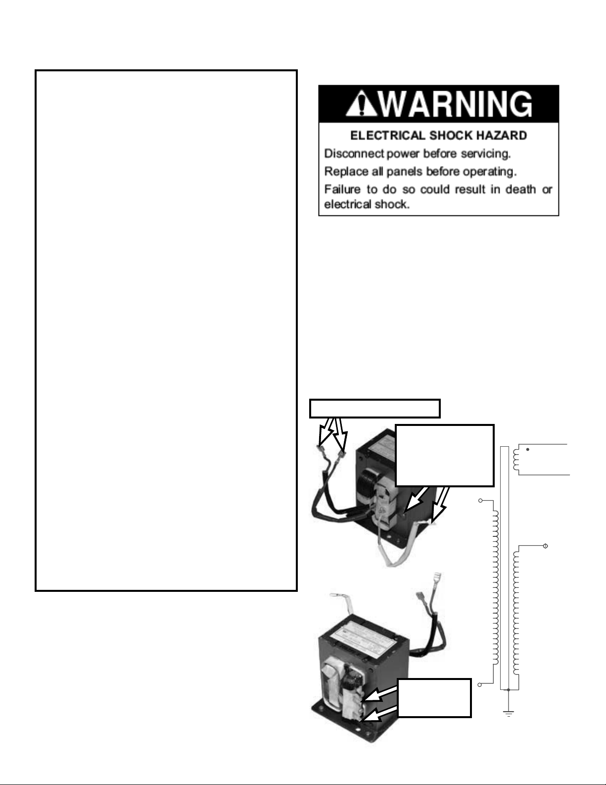
H.V. TRANSFORMER
• Discharge the high-voltage capacitor and
remove the lead wires from the primary winding
of the high-voltage transformer before conducting any of the following tests.
• All operational checks using microwave
energy must be done with the microwave oven
loaded with a minimum of 8 oz (250 mL) of water in a microwave safe container.
• Conduct a microwave energy test after performing any tests or repairs to the microwave
oven.
• Check that all wire leads are in the correct
positions before operating the microwave oven.
• Grasp wire connectors when removing the
wire leads from microwave oven parts.
• All testing must be done with an ohmmeter
having a sensitivity of 20,000 ohms per volt DC
or greater, and powered by at least a 9-volt battery
1. Unplug microwave oven or disconnect power.
2. Remove wire leads.
3. Measure resistance (ohmmeter scale: Rx1):
• Primary winding: Less than 0.5 ohm (approximate)
• Secondary winding: 80 ohms (approximate)
• Filament winding: 0 ohms
4. Measure resistance (ohmmeter scale: Rx1k):
• Primary winding to grounding: Normal: Innite
• Filament winding to grounding: Normal: Innite
Filament (black & red)
Secondary
(white wire,
ground to trans-
former case)
Red Tube
Black Tub e
White
Tube
5-1
Primary
(terminals)
Page 40
MAGNETRON
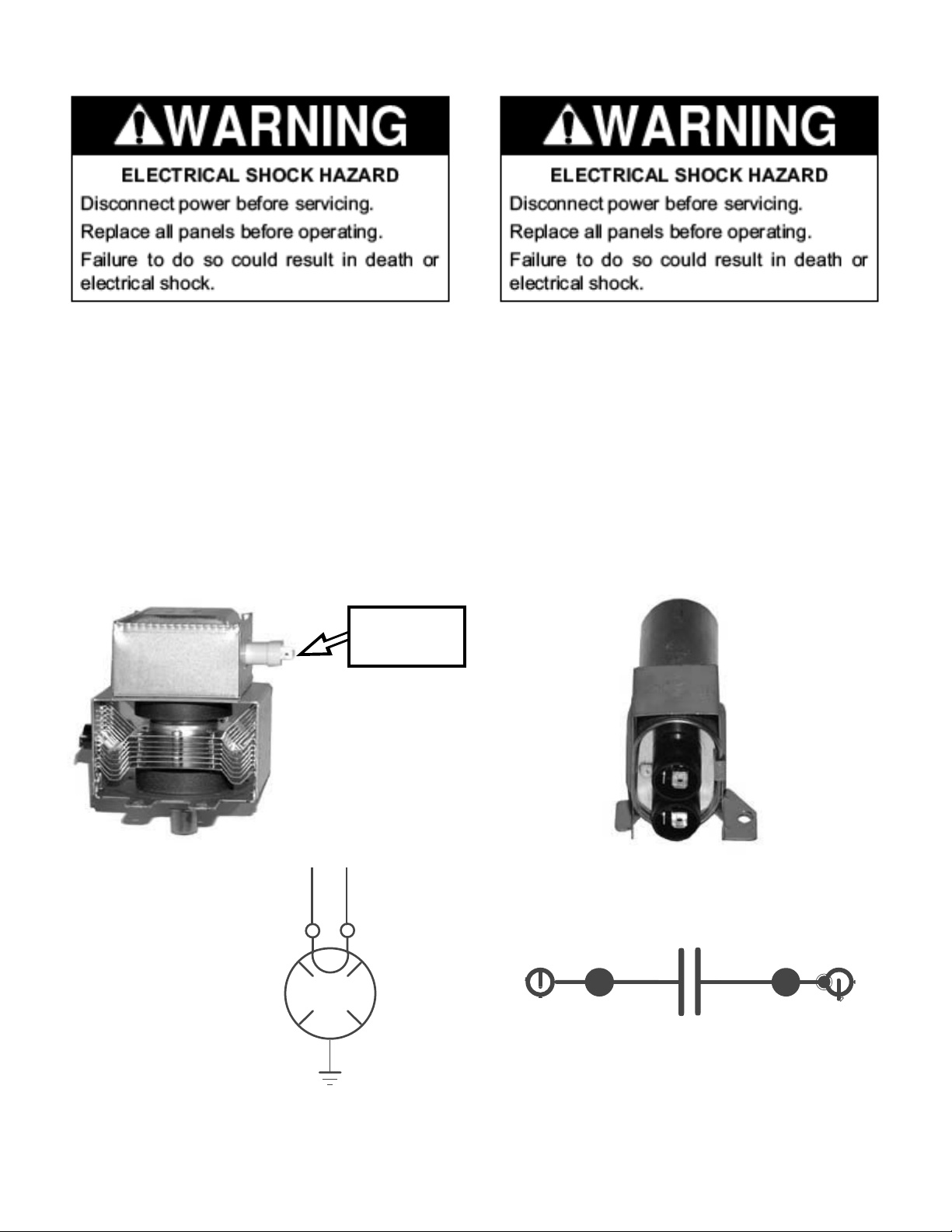
H.V. CAPACITOR
1. Unplug microwave oven or disconnect power.
2. Remove wire leads. Check that the seal is in
good condition.
3. Measure resistance (ohmmeter scale: Rx1):
• Filament terminal: Normal: Less than 1 ohm
4. Measure resistance (ohmmeter scale: Rx1k):
• Filament to chassis: Normal: Innite
Filament
Terminals
1. Unplug microwave oven or disconnect power.
2. Remove wire leads.
3. Measure resistance (ohmmeter scale: Rx10k):
• Terminal to terminal: Normal: Momentarily indicates several ohms, and then gradually returns
to innite.
• Terminal to case: Normal: Innite
Magnetron
F
FA
5-2
Page 41
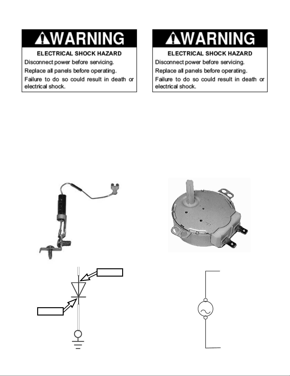
H.V. DIODE
TURNTABLE MOTOR
NOTE: Some inexpensive meters may indicate
innite resistance in both directions.
1. Unplug microwave oven or disconnect power.
2. Measure resistance (ohmmeter scale: Rx1k):
• Forward: Normal: Continuity; Abnormal: Innite
• Reverse: Normal: Innite; Abnormal: Continuity
1. Unplug microwave oven or disconnect power.
2. Remove wire leads.
3. Measure resistance (ohmmeter scale: Rx1k):
• Turntable Motor—Normal: 2.7k-3.8k ohms (ap-
proximate); Abnormal: Innite
Cathode
Anode
TTM
5-3
Page 42
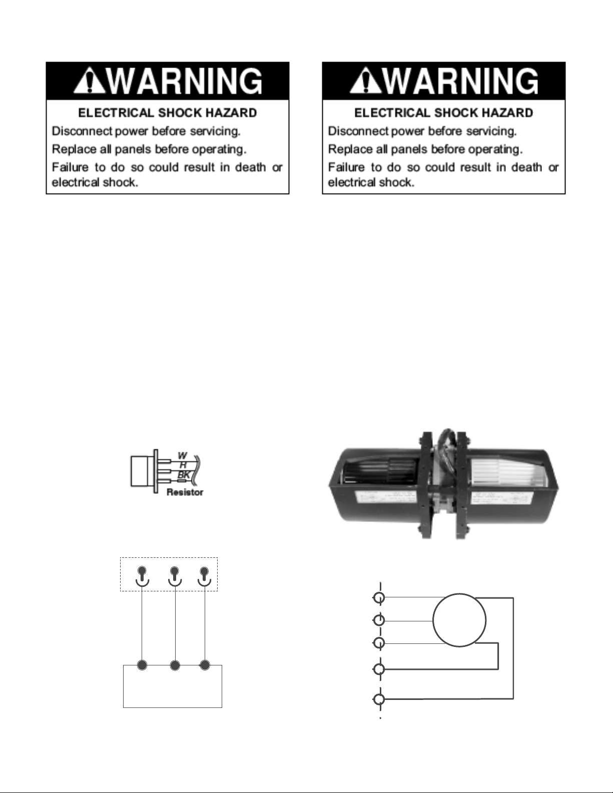
HUMIDITY SENSOR
HOOD EXHAUST FAN MOTOR
1. Unplug microwave oven or disconnect power.
2. Remove the 3-pin connector from the electronic control (P1). NOTE: Do not remove the
attached resistor, which is used for internal
resistance calibration.
3. Measure resistance across pins 1 & 3, and
across pins 2 & 3 (ohmmeter scale: Rx1k):
• Normal: 2.8k ohms (approximate) at 77ºF
(28ºC) +/- 18ºF (-10ºC)
• Abnormal: Innite
1. Unplug microwave oven or disconnect power.
2. Remove wire leads.
3. Measure resistance (ohmmeter scale: Rx1):
• High Speed—Normal: Red (R) and Blue (BU)
wires: 100-200 ohms (approximate); Blue (BU)
and Black (BK) wires: 40-100 ohms (approxi-
mate) ; Abnormal: Innite
• Low Speed—Normal: Red (R) and Blue (BU)
wires: 100-200 ohms (approximate); Blue (BU)
and White (W) wires: 80-150 ohms (approxi-
mate); Abnormal: Innite
1
BK
R
W
BK
W
HF
BU
Y
R
5-4
Page 43
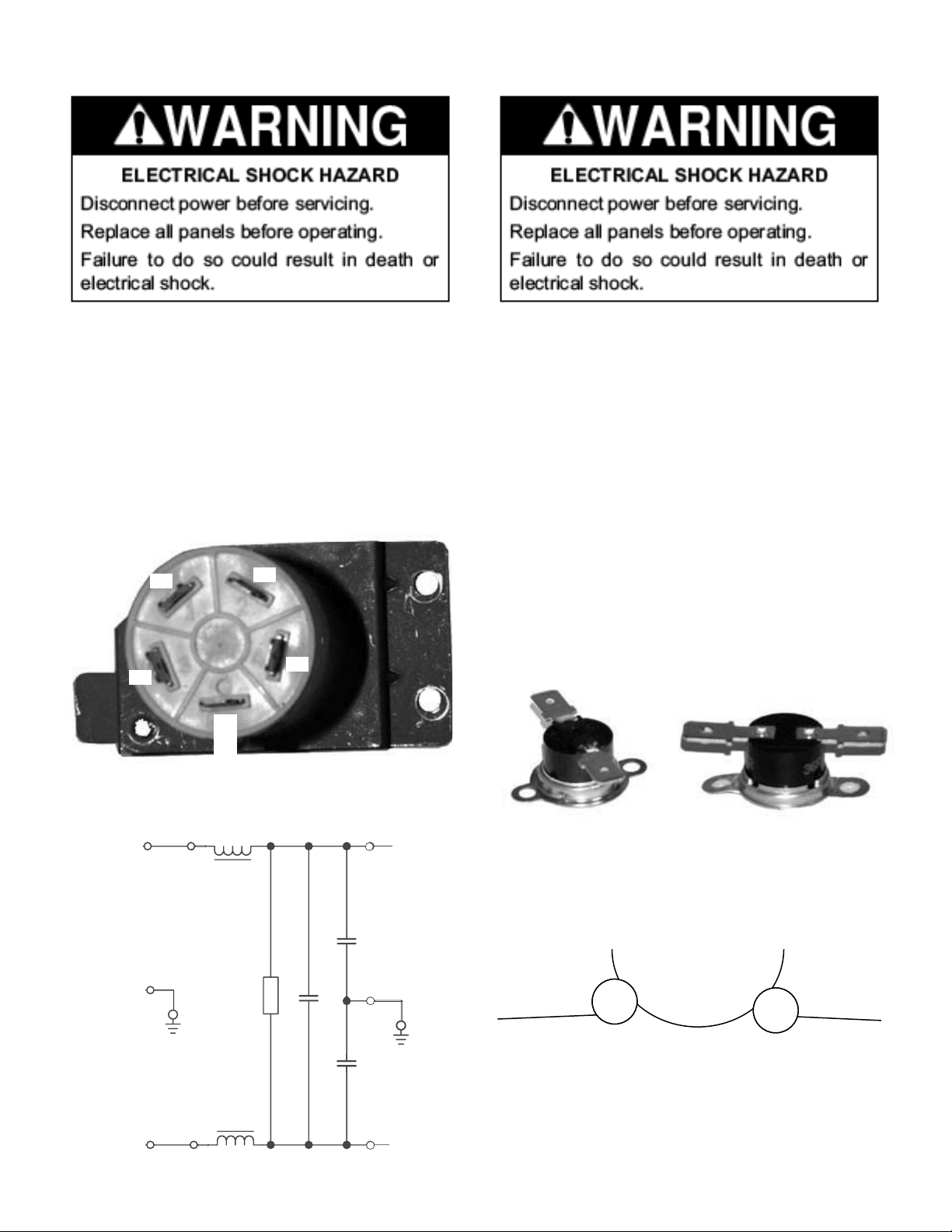
AC LINE FILTER
THERMOSTATS
1. Unplug microwave oven or disconnect power.
2. Remove wire leads.
3. Measure resistance (ohmmeter scale: Rx1):
• Normal: 1-3 (coil): Less than 1 ohm; 2-4 (coil):
Less than 1 ohm; 3-4 (resistor): 550k-800k
ohms
• Abnormal: Innite
1
2
4
3
1. Unplug microwave oven or disconnect power.
2. Remove wire leads.
3. Measure continuity (ohmmeter scale: Rx1)
• Cavity and Magnetron Thermostats—
Normal: Continuity; Abnormal: Innite
• Magnetron thermostat opens at 257ºF (125ºC),
closes at 185ºF (85ºC)
• Cavity thermostat 1 opens at 257ºF (125ºC),
closes at -31ºF (-35ºC)
• Cavity thermostat 2 opens at 257ºF (125ºC),
closes at -31ºF (-35ºC)
L
GND
N
BK
G
W
1
2
Ground
L
R
Cx
L
3
Cy
Cy
4
5-5
Page 44

---- NOTES ----
5-6
Page 45
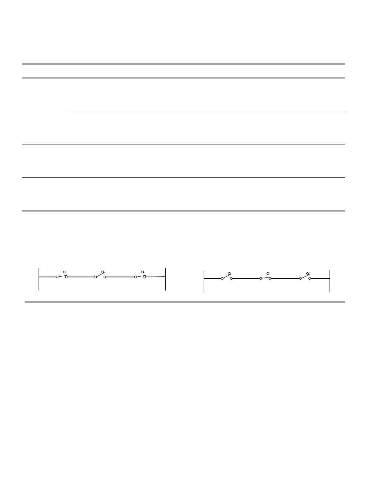
Primary
Interlock
DIAGNOSIS & TROUBLESHOOTING
INTERLOCK SWITCH CHECKOUT PROCEDURES
1. Unplug microwave oven or disconnect power.
2. Disconnect the wires at the Primary Interlock Switch.
3. Check from the common terminal (black/brown wires) to the
normally open terminal (black/white wires).
1. Unplug microwave oven or disconnect power.
2. Disconnect the wires at the Primary Interlock Switch.
3. Check from the common terminal (black/brown wires) to the
normally closed terminal (orange wire).
- +
+ -
desolC rooDnepO rooDyB kcehChctiwS
Secondary
Interlock
Monitor
Interlock
(+) Continuity (-) No Continuity
NOTE: These diagrams are not intended to show a complete circuit; they represent the position of switches during “DOOR
OPEN” or “DOOR CLOSED” (continuity checks only).
1. Unplug microwave oven or disconnect power.
2. Disconnect the wires at the Secondary Interlock Switch.
3. Check from the common terminal (blue/white wires) to the
normally open terminal (blue wires).
1. Unplug microwave oven or disconnect power.
2. Disconnect the wires at the Monitor Interlock Switch.
3. Check from the common terminal (white wire) to the normally
closed terminal (blue/white wires).
- +
+ -
nepO rooDdesolC rooD
(NO)
N
(NC)
Primary
Interlock
Switch
(NO)
(NO)
Monitor
Interlock
Switch
(NC)
(NC)
Secondary
Interlock
Switch
NL
(NO)
L
(NC)
Primary
Interlock
Switch
(NO)
(NO)
Monitor
Interlock
Switch
(NC)
(NC)
Secondary
Interlock
Switch
TROUBLESHOOTING
Do not continue with the diagnostics of appliance if the
household fuse is blown, a circuit breaker is tripped or if there
is less than 120-volt power supply at the wall outlet.
Complete the following steps before checking microwave
oven circuitry:
1. Unplug microwave oven or disconnect power.
2. Check for loose wiring or incorrect wiring within
microwave oven.
3. Disconnect white wire from power transformer and
discharge high-voltage capacitor.
4. All testing must be done with an ohmmeter having a
sensitivity of 20,000 ohms per volt DC or greater, and
powered by at least a 9-volt battery.
5. All operational checks using microwave energy must be
done with the microwave oven loaded with a minimum of
8 oz (250 mL) of water in a microwave safe container.
6-1
Page 46
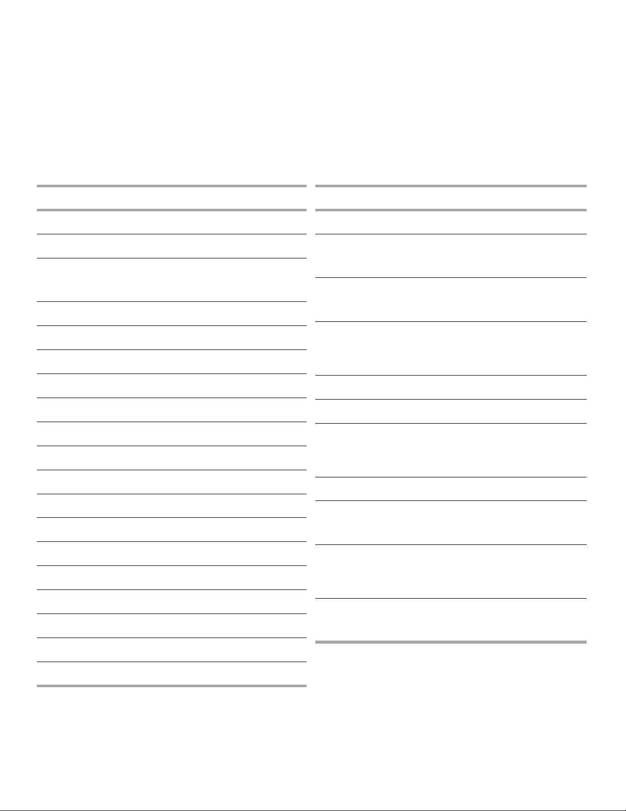
TOUCH PANEL AND ELECTRONIC CONTROL TEST
Touch Panel and Electronic Control Test
The microwave hood combination is provided with a self-diagnostic routine that can be accessed through the touch keypad.
To initiate this routine:
1. Press and hold the OFF/CANCEL button while opening
the door. While still holding the OFF/CANCEL button,
unplug the microwave oven for 2 seconds, then plug it
back in.
2. Release the OFF/CANCEL button and close the door. All
VFD segments will be lit to indicate the test mode has
been entered.
NOTE: If the OFF/CANCEL button is pressed during this
diagnostic routine, you will exit the test mode.
Key Tables for Test Mode
Key Name Function Display Buzzer
peeb 11 yeK-tratS
Light Hi/Lo/Off - Key 3 1 beep
Hood Exhaust Fan
(HF) Hi/Med/Lo/
Off
- Key 4 1 beep
Turntable On/Off - Key 5 1 beep
Clock - Key 6 1 beep
Timer Set/Off - Key 7 1 beep
Add 30 Sec - Key 9 1 beep
Cook Time - Key 10 1 beep
Cook Power - Key 11 1 beep
Warm Hold - Key 12 1 beep
Cook - Key 13 1 beep
Reheat - Key 14 1 beep
Defrost - Key 15 1 beep
Frozen Entrée - Key 16 1 beep
Beverage - Key 17 1 beep
Popcorn - Key 18 1 beep
Baked Potato - Key 19 1 beep
Frozen Vegetable - Key 21 1 beep
Fresh Vegetable - Key 22 1 beep
Key Name Function Display Buzzer
peeb 123 yeK-0
1
Cavity Light
On—Relay
4901
Key 33 1 beep
2
Cooktop Light
On (High)—
Relay 4911
Key 34 1 beep
3
Microwave
Oven On for
10 Seconds—
Relay 4903
Key 35 1 beep
peeb 163 yeK-4
peeb 173 yeK-5
6
Cavity Light &
Turntable On—
Relay 4901
&4906
Key 38 1 beep
peeb 193 yeK-7
8
Cooktop Light
On (Night)—
Relay 4912
Key 40 1 beep
9
HF On (High
Speed)—
Relay 4902 &
Triac 7104
Key 41 1 beep
Off/Cancel (to
lock hold, hold
for 3 seconds)
Exit Test Mode - 1 beep
6-2
Page 47

MICROWAVE OVEN POWER OUTPUT TEST
1. Place 8 oz (250 mL) of lukewarm water in the center of the
microwave oven.
2. Operate on HIGH power level for 2 minutes. Water
should be hot.
NOTE: If the water takes longer than 2 minutes to heat,
this may indicate either the operating voltage is lower
than 110 volts or there is a problem with the microwave
oven.
FAILURE CODES INDICATIONS
Display Likely Failure Condition Recommended Repair Procedure
Flashing
colon “:”
F2 Touch panel failure 1. Unplug microwave oven or disconnect power.
F3H Humidity sensor failure 1. Unplug microwave oven or disconnect power.
Power failure After a power failure, the colon “:” will be flashing. Press any key to end this
indication. The colon will then be steady when in standby.
2. Replace touch panel.
3. Plug in microwave oven or disconnect power.
4. If problem persists, unplug microwave oven or disconnect power.
5. Replace electronic control.
6. Plug in microwave oven or reconnect power.
2. Connect a new sensor to the electronic control (at P1).
3. Plug in microwave oven or reconnect power.
4. If problem persists, unplug microwave oven or disconnect power.
5. Replace electronic control.
6. Plug in microwave oven or reconnect power.
F6 Microwave relay failure 1. Unplug microwave oven or disconnect power.
2. Check wiring to Relay 4903 for short circuits.
3. If wiring is OK, replace electronic control.
4. Plug in microwave oven or reconnect power.
6-3
Page 48

---- NOTES ----
6-4
Page 49
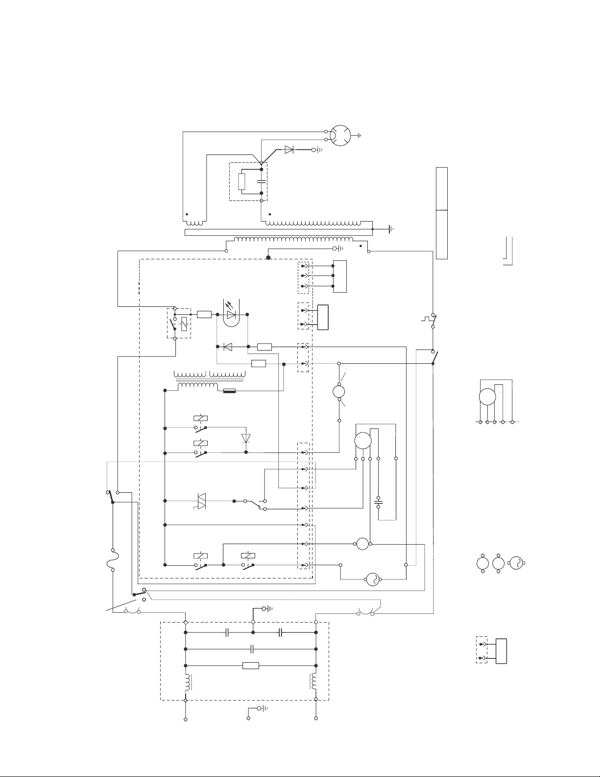
WIRING DIAGRAM & STRIP CIRCUITS
AC Line Filter
1
BK
L
3
L
GND
G
N
W
2
L
R
Cy
Cy
Cx
32Y/G
1
BK
3BR
Moni tor
Inte rlock
Swit ch
Fuse
20
2
BK
Primary
Interlock
Switch
4OR
6 B K
5W
El ectron i c Contr o l
7 BR
MW-R elay
4903
2 1
Red Tub e
Blac k T ub e
Whit e
Tube
R
C
H.V. Capac itor
H.V. Diode
3
3K
1
2
GND
Sec.
L.V.
Transformer
Pri.
33
K
6
8
K
HF NTC
HL Relay
4912
H
L
Relay
4
9
1
1
Diod e
6101
HF Triac
7104
HF Relay
4902
HL
HF1
HF2
Doo r
N1
NFS
CL
Rela y
4901
TTM
Rela y
4906
TTM
CL
L
18
R
19
W
17
R
1P5
CL
16
GY
11
W
2P5
22W
26W
10BU
27Y
28R
25BK
5P6
1P6
BK
B
U
R
Y
W
15Y
5P5
(Golden
tab)
(White
tab)
P2
P3
1
20
R
HL
21W
13BU
14
G
4P5
30Y/
G
Magn et ron
F
FA
31
R(
HV
)
H.V.
Tran sf orm er
Magnet ro n
Thermo st at
29W
24BU
HF
Seco nd ar y
Inte rl ock
Swit ch
23BU
12W
TTM
Condition: Door
Open
Symbol Notes
Cavi ty Lam p
Turn table Motor
TTM
BUWBK
Y
R
HF
Hood Ex haust
Fan M ot or
DWG NO. MU-0 76
P1/P 2/ P3/P4 /P 5/ P6: Co nne ctors
R: Red
Y: Yell ow
OR: Ora ng e
W: White
G: Gre en
GY: G ra y
BR: Br ow n
BU: Bl ue
BK: Bl ac k
1
BK
Wire NO. -1
Wire Col or-Bl ac k
Moto r
Capa citor
CL
Hood (Cook top) L amp
HL
1
P1
Humi dity
Sens or
Amp
BK
R
W
4
8B
U
TTM
9BU
Cavity
Thermostat 1
33
BK
Cavity
Ther mos tat 2
P4
AC 120 V/1 25V 60H z
HF NTC
P4
(White
tab)
(Golden
tab)
1
WIRING DIAGRAM - 8205889 - SENSOR MODEL
7-1
Page 50
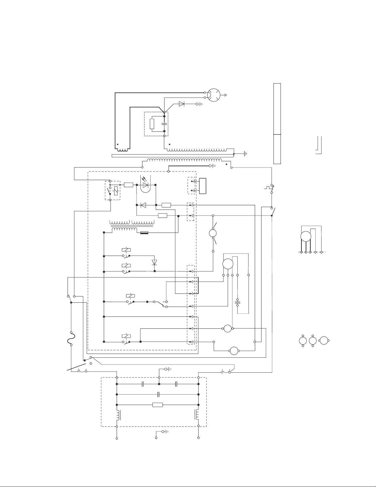
AC Li ne Fil te r
1
BK
L
3
L
GND
G
N
W
2
L
4
R
Cy
Cy
Cx
32 Y/G
1
B
K
8
B
U
3
B
R
Moni tor
Inte rlo ck
Swit ch
Fuse
20Am p
2BK
Prim ary
Inte rlo ck
Swit ch
4OR
6BK
5W
Elec tro nic C ontrol
7BR
MW-Rel ay
4903
2 1
Red Tub e
Blac k T ub e
White
Tube
R
C
H.V. Ca pacit or
H.V. Di ode
3
3
K
1
2
GND
Sec.
L.V.
Tra ns forme r
Pri.
3
3
K
68
K
Hood
Thermi st or
HL
Rela y
4911
Diode
6101
HF R el ay
4905
HF Rel ay
4902
HL
HF1
HF2
Doo r
N1
NFS
CL
Rela y
4901
TTM
CL
L
1
8
R
1
9
W
1
9
W
17
R
1P5
CL
1
6
G
Y
1
1
W
2P5
22 W
26 W
10
BU
27
Y
28 R
25B
K
5P6
1P6
BK
BU
R
Y
W
15 Y
5P5
(Golde n
tab)
(White
tab)
P2
P3
1
20R
HL
21W
1
3B
U
14
G
4P5
30Y
/
G
Magn et ron
F
FA
3
1
R
(
H
V
)
H.V.
Transf or mer
Magnet ro n
Thermo st at
29W
24BU
HF
Second ar y
Interl oc k
Switch
23 BU
12 W
TT
Condition: Door Opened.
Symbol Notes
Cavi ty Lamp
Turn ta ble Mo to r
TT
BU
W
BK
Y
R
HF
Hood Ex haust
Fan M ot or
DWG N O. MU-079 ( Rev. A)
P2/P 3/ P4/P5 /P 6: Con ne ctors
R: Red
Y: Y ell ow
OR: Or an ge
W: White
G: Gre en
GY: G ray
BR: Br ow n
BU: Bl ue
BK: Bl ac k
1
BK
Wire NO. -1
Wire Col or-Bl ac k
Motor
Capacitor
CL
Hood (C ookto p) Lamp
HL
1
33 B K
9
BU
Cavity
Thermostat 1
Cavi ty
Thermostat 2
(Golde n
tab)
(White
tab)
HL
Rela y
4912
AC 120 V/ 12 5V 6 0H z
P4
WIRING DIAGRAM - 8205660 - NON SENSOR MODEL
7-2
Page 51
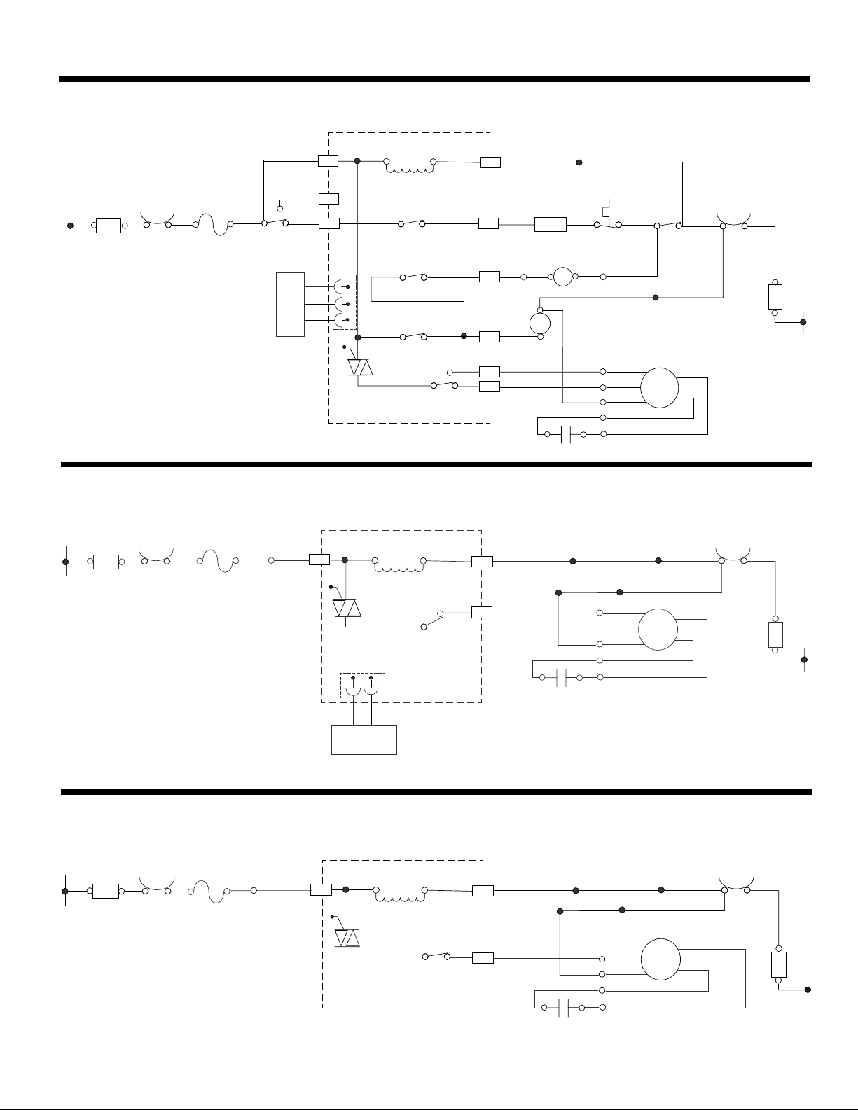
STRIP CIRCUITS
MICROWAVE COOKING
Elec tr oni c C ontro l
L.V.
P1
1
Tran sf ormer
MW Re la y
4903
TTM R el ay
4906
CL Re la y
4901
HF Tria c
7104
HF Re la y
4902
1P3
1
7P2
6P2
2P2
4P2
R
Cavi ty
Lamp
Tran sf ormer
BR
1P5
GY
Moto r Capac itor
BR
5P2
OR
3P2
BK
2
Humi dity
Sens or
BK
R
W
BK
Fuse
20AM P
BK
Prim ar y
Inte rl ock
Swit ch
L
Filt er
BK
BK
Cavi ty
Ther mo stat 2
G
H.V.
Turn ta ble
Moto r
R
TT
CL
4P5
Magn et ron
Ther mo stat
W
W
2P5
1P6
BK
W
BU
Y
R
BU
BK
W
BU
Y
R
5P6
Seco nd ary
Inte rl ock
Swit ch
BU
BU
W
HF
Ther mo stat 1
W
BU
Cavi ty
BU
N
Filt er
W
HOOD EXHAUST FAN ON HIGH AUTOMATICALLY
Cavi ty
Filt er
Ther mo stat 2
BK
BK
Fuse
20 Amp
BK
BR
5P2
L
BK
Elec troni c Cont rol
L.V.
Tran sform er
HF Tria c
7104
P4
HF NT C
HF Re lay
4902
1P3
2P2
Moto r
G
Capa citor
4P5
BK
BU
Y
R
BU
W
1P6
5P6
BK
BU
Y
R
HF
Cavi ty
Ther mosta t 1
W
BU
BU
N
Filter
W
HOOD EXHAUST FAN ON LOW SPEED
L
BK
Filt er
Cavi ty
Ther mosta t 2
BK
BK
Fuse
20 Amp
BK
BR
5P2
Elec troni c Co nt rol
L.V.
Tran sform er
HF Tria c
7104
HF Re lay
4902
1P3
4P2
4P5
G
Moto r
Capa citor
W
BU
Y
W
R
2P6
5P6
BU
W
BU
HF
Y
R
Cavi ty
Ther mosta t 1
W
BU
BU
N
Filt er
W
7-3
Page 52
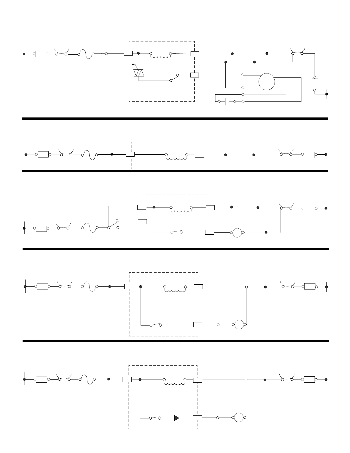
HOOD EXHAUST FAN ON HIGH / MEDIUM
L
BK
Filt er
Cavi ty
Ther mo stat 2
BK
BK
Fuse
20 Amp
BK
BR
5P2
Elec troni c Co nt rol
L.V.
Tran sform er
HF Tria c
7104
HF Re lay
4902
1P3
2P2
4P5
G
Moto r
Capa citor
BK
BU
Y
R
W
1P6
5P6
BU
BK
BU
Y
R
HF
Cavi ty
Ther mosta t 1
W
BU
BU
Filt er
MICROWAVE OVEN PLUGGED IN—TIME OF DAY DISPLAYED
Elec tro nic Co ntr ol
L.V.
Tran sform er
1P3
4P5
G
BU
W
Cavi ty
Ther mos tat 1
Filt er
BU
BK
Fuse
20 A mp
BK
BR
5P2
L
Filt er
BK
BK
Cavi ty
Ther mosta t 2
DOOR OPEN—OVEN CAVITY LIGHT IS ON
Elec tro nic Co ntr ol
L.V.
BR
5P2
BK
Fuse
20 Amp
BK
Prim ary
Inte rlo ck
Swit ch
L
Filt er
BK
BK
Cavi ty
Ther mosta t 2
OR
3P2
Tran sform er
CL Re lay
4901
1P3
6P2
GY
4P5
G
CL
Cavi ty
Lamp
BU
W
Cavi ty
Ther mosta t 1
W
BU
BU
Filt er
N
W
N
W
N
W
COOKTOP LIGHT ON HIGH
L
BK
Filt er
Cavi ty
Ther mosta t 2
BK
BK
Fuse
20 Amp
BK
BR
5P2
Elec tro nic Contr ol
L.V.
Tran sform er
HL Re lay
4911
1P3
1P2
Cavi ty
Ther mos tat 1
W
BU
Filt er
R
4P5
W
HL
Hood
Lamp
BU
G
5P5
Y
N
W
COOKTOP LIGHT ON LOW (NIGHT LIGHT)
L
BK
Filt er
Cavi ty
Ther mosta t 2
BK
BK
Fuse
20 Amp
BK
BR
5P2
Elec tro nic Contr ol
L.V.
Tran sform er
HL Re lay
4912
Diod e
6101
Cavi ty
1P3
1P2
G
5P5
Y
R
(Coo kto p) L amp
W
HL
Hood
4P5
BU
Ther mos tat 1
W
BU
Filt er
N
W
7-4
Page 53

PRODUCT SPECIFICATIONS
AND
WARRANTY INFORMATION SOURCES
IN THE UNITED STATES:
FOR PRODUCT SPECIFICATIONS AND WARRANTY INFORMATION CALL:
FOR WHIRLPOOL PRODUCTS: 1-800-253-1301
FOR KITCHENAID PRODUCTS: 1-800-422-1230
FOR ROPER PRODUCTS: 1-800-447-6737
FOR TECHNICAL ASSISTANCE WHILE AT THE CUSTOMER’S HOME CALL:
THE TECHNICAL ASSISTANCE LINE: 1-800-253-2870
HAVE YOUR STORE NUMBER READY TO IDENTIFY YOU AS AN
AUTHORIZED SERVICER
FOR LITERATURE ORDERS:
PHONE: 1-800-851-4605
FOR TECHNICAL INFORMATION AND SERVICE POINTERS:
www.servicematters.com
IN CANADA:
FOR PRODUCT SPECIFICATIONS AND WARRANTY INFORMATION CALL:
1-800-461-5681
FOR TECHNICAL ASSISTANCE WHILE AT THE CUSTOMER’S HOME CALL:
THE TECHNICAL ASSISTANCE LINE: 1-800-488-4791
HAVE YOUR STORE NUMBER READY TO IDENTIFY YOU AS AN
AUTHORIZED SERVICER
Page 54

 Loading...