

Page 1
CONSUMER SERVICES TECHNICAL
EDUCATION GROUP PRESENTS
POINT VOYAGER DISHWASHER
KD-12
MODEL NUMBERS:
GU1200XT
GU1500XT
JOB AID
Part No. 8178022
I
Page 2

INTRODUCTION
This Job Aid, POINT VOYAGER DISHWASHER, Part No. 8178022 provides specific information on
the operation, diagnosis and repair of the Whirlpool Point Voyager series Undercounter Dishwasher.
POINT VOYAGER DISHWASHER has been compiled to provide the most recent information on design, features, operation, troubleshooting, and repair procedures.
GOALS AND OBJECTIVES
The goal of this Job Aid is to provide detailed information that will enable the service technician to
properly diagnose malfunctions and repair the Point Voyager dishwasher.
The objectives of the Job Aid are:
The service technician will -
• Understand proper safety precautions.
• Successfully troubleshoot and diagnose malfunctions.
• Successfully perform necessary repairs.
• Successfully return the dishwasher to proper operational status.
WHIRLPOOL CORPORATION ASSUMES NO RESPONSIBILITY
FOR ANY REPAIRS MADE ON OUR PRODUCTS BY ANYONE
OTHER THAN AUTHORIZED SERVICE TECHNICIANS.
© 2000 Whirlpool Corp., Benton Harbor, MI 49022
PB
Page 3

TABLE OF CONTENTS
MODEL/SERIAL NUMBER DESIGNATORMODEL/SERIAL NUMBER DESIGNATOR
MODEL/SERIAL NUMBER DESIGNATOR
MODEL/SERIAL NUMBER DESIGNATORMODEL/SERIAL NUMBER DESIGNATOR
Section One
INSTALLATION CONSIDERATIONSINSTALLATION CONSIDERATIONS
INSTALLATION CONSIDERATIONS
INSTALLATION CONSIDERATIONSINSTALLATION CONSIDERATIONS
GENERAL CONSIDERATIONS...............................................................1
SPECIFICA-SPECIFICA-
SPECIFICA-
SPECIFICA-SPECIFICA-
TIONS....................................................................................TIONS....................................................................................
TIONS....................................................................................
TIONS....................................................................................TIONS....................................................................................
22
2
22
Section Two
THEORY OF OPERATIONTHEORY OF OPERATION
THEORY OF OPERATION
THEORY OF OPERATIONTHEORY OF OPERATION
CONTROL PANEL ...................................................................................3
Model: GU1200XTK
Cycle Selection Chart .................................................................. 3
Option Selection ..........................................................................5
Cycle Status Indicators ...............................................................6
CONTROL PANEL ...................................................................................7
Model: GU1500XTK
Cycle Selection Chart .................................................................. 7
FUNCTION DESCRIPTION......................................................................9
............................................................................
......................................
............................................................................
....................................................
..........................
....................................................
............................................................
..............................
............................................................
iviv
iv
iviv
11
1
11
33
3
33
Section Three
COMPONENT ACCESSCOMPONENT ACCESS
COMPONENT ACCESS
COMPONENT ACCESSCOMPONENT ACCESS
COMPONENT LOCATION.....................................................................13
ACCESSING COMPONENTS IN THE DOOR ....................................... 14
ACCESSING COMPONENTS INSIDE THE TUB ..................................17
ACCESSING COMPONENTS OF THE PUMP ASSEMBLY .................20
SERVICING THE DOOR HINGE....................................................................23
Section Four
TROUBLESHOOTING AND DIAGNOSISTROUBLESHOOTING AND DIAGNOSIS
TROUBLESHOOTING AND DIAGNOSIS
TROUBLESHOOTING AND DIAGNOSISTROUBLESHOOTING AND DIAGNOSIS
TROUBLESHOOTING CHART.............................................................. 25
COMMON CYCLE TIME CHART...........................................................26
HOW TO USE COMMON CYCLE TME ................................................. 28
COMMON CYCLE TIME CHART NOTES ............................................. 31
DIAGNOSTIC CYCLE TIME CHART.....................................................35
RAPID ADVANCE FEATURE & DIAGNOSTIC CYCLES...................... 36
Section Five
TECH TIPSTECH TIPS
TECH TIPS
TECH TIPSTECH TIPS
WIRING DIAGRAM ................................................................................ 37
MODEL SPECIFIC SERVICE PARTS TABLE .......................................38
USER INTERFACE SWITCH MATRIX...................................................38
STRIP CIRCUITS ................................................................................... 39
ELECTRONIC CONTROL CONNECTOR PINS ....................................40
..............................................................................................
...............................................
..............................................................................................
................................................................................
........................................
................................................................................
......................................................
...........................
......................................................
1313
13
1313
2525
25
2525
3737
37
3737
III
Page 4
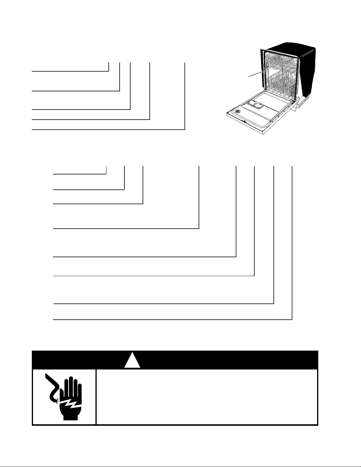
MODEL/SERIAL NUMBER PLATE
SERIAL NUMBER DESIGNATOR
SERIAL NUMBER
MANUFACTURING SITE
F = Findlay , OH
YEAR OF MANUFACTURE
L = 2001
WEEK OF MANUFACTURE
PRODUCT SEQUENCE NUMBER
F L 36 50001
MODEL NUMBER DESIGNATOR
MODEL NUMBER
Product Group
G = Gold Series Dishwasher
Product Identification
U = Undercounter
Series Code
800 = Baseline and Contract Models
900 = Midline and Retail Derivatives
1000 = Voyager Platform
G 1500
U
Model/Serial
Number Plate
(Left side of
frame behind
door)
XT K
B
0
Feature Code
PW = Premium Wash System
SW = Standard Wash System
XT = Extra Tall Tub
Year of Introduction
K = 2001
Color Code
B = Black Monochromatic
Q = White Monochromatic
T = Bisquit Monochromatic w/frameless panel
S = Black Console w/Stainless Steel panel
ENGINEERING CHANGE
0 = Basic Release; 1 = First Revision; 2 = Second Revision
SAFETY
! WARNING
ELECTRICAL SHOCK HAZARD
Disconnect power before servicing the dishwasher.
Replace all panels before operating the dishwasher.
Failure to do so can result in death or electrical shock.
PB
Page 5
SECTION ONE
INSTALLATION CONSIDERATIONS
GENERAL CONSIDERATIONS
For complete installation procedures see the “Installation Instructions” in the
literature packet provided with the dishwasher .
A video presentation, Key Features and Installation Considerations, part number
4317280V, is available. This video covers the entire installation process.
Each location will present a different set of challenges that can be anticipated and solved before installation begins.
• Check the planned location of the dishwasher.
• Easy access to hot water, drain line and electricity.
• Convenient access for loading. The dishwasher door should open and close freely .
• The opening under the counter should be square and the cabinet fronts should be perpendicular to the floor.
• Make sure the cabinet opening is free of intrusions such as braces or utility lines.
• Do not install the dishwasher on carpeted floors.
• An outside wall behind the dishwasher should be insulated to prevent the water line, inlet valve
and drain line from rupturing.
The application of a horizontal pump and filter
technology allows for the tub to be designed three
inches deeper than current models. This deeper
tub and longer door design will impact the installation process because there is less working
space available underneath the unit and correct
routing and placement of the drain hose, water
supply and electrical wiring is critical.
The tub must be level. Reduced water consumption of this dishwasher requires that it be installed
level and plumb for proper water recirculation back
into the sump area during operation.
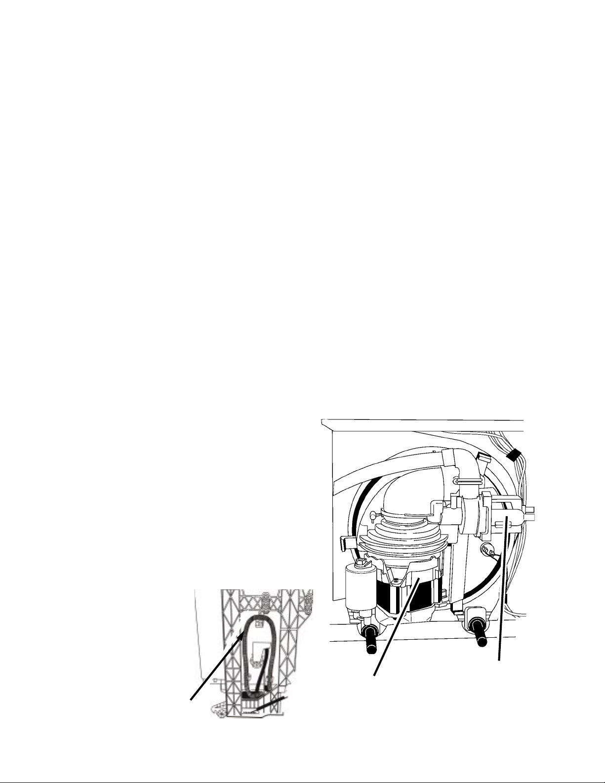
Do not remove the drain
hose from the left side of
the tub. This loop in the
drain hose provides proper back pressure for the
soil sensor. If the loop is
removed, the dishwasher
will not initiate Automatic
Purge Filtration.
Drain Hose
Loop
Main Wash Motor
View of Sump Assembly from Underneath
Showing Horizontal Wash Pump Motor
and Drain Pump Motor
Drain Pump
Motor
1
Page 6

SPECIFICATIONS
ELECTRICAL SUPPLY: (Under Load) 60Hz, 120V AC
SUPPLY WATER FLOW RATE: (To Fill 2 Quarts (1.9 L) in 27 secs.) - 120psi Max., 20psi Min.
SUPPLY WATER TEMPERATURE: 120° F to 160° F (49° C to 71° C)
WA TER CHARGE: 1.8 Gal. (6.8 L) / First Fill
1.7 Gal. (6.5 L) / All Other Fills
LOWER SPRAY ARM ROTATION: 25 TO 40 RPM
UPPER SPRAY ARM ROTATION: 25 TO 35 RPM
APF DRAIN: .1 Gal. (.38 L)
HEATING ELEMENT HEATING RATE: 1°+ F Rise per Minute
2
Page 7
MODEL: GU1200XTK
SECTION TWO
THEORY OF OPERATION
CONTROL PANEL
248
CYCLES
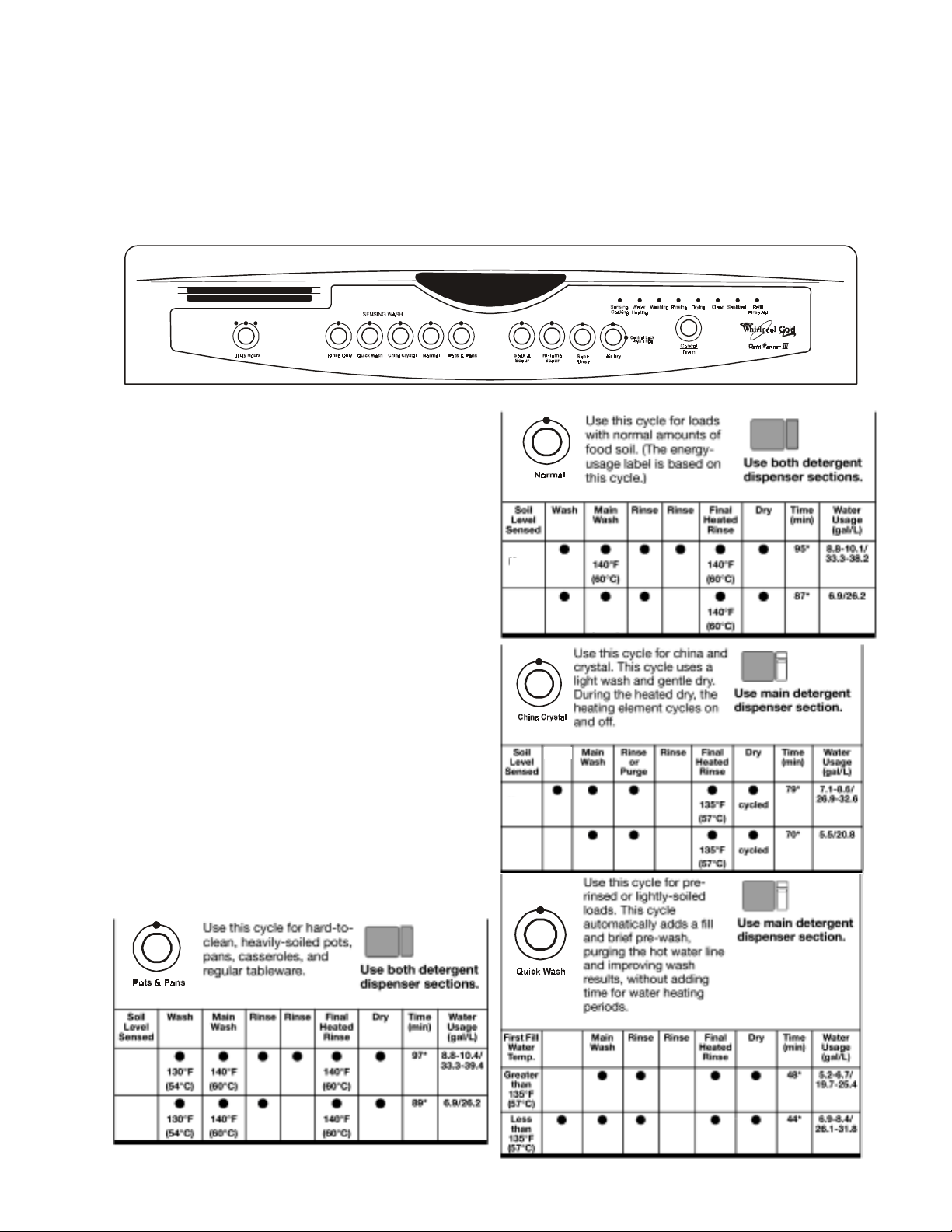
CYCLE SELECTION CHART
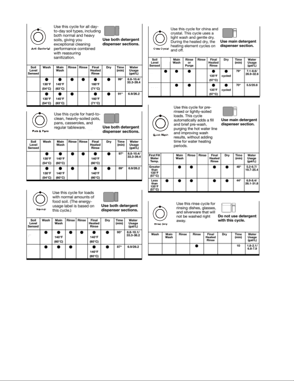
Select the wash cycle and options desired. Upon
selecting the cycle key , the cycle will begin immediately . Cycles may be changed at any time, during the first fill. Options can be selected or
changed at any time.
NOTE: The last options used will be recalled from
memory automatically upon selecting a cycle, (if
the option is valid with the cycle selected).
A “ ” shows what steps are in each cycle.
•
T emperatures indicate where extra heat is added.
Water usage is shown in U.S. gallons/liters.
Cycle time includes dry time. An asterisk (*) by
the cycle time indicates the cycle time might be
longer depending on the temperature of the water
entering the dishwasher. The cooler the water,
the longer the cycle time. If the water is already
hot enough, the cycle time will be as shown.
High
Low 130 F
High
Low
Rinse
(54 C)
º
º
Purge
Pots & Pans
High
Low
Rinse
3
Page 8
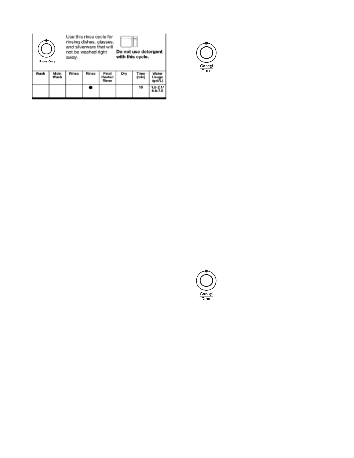
NOTE: The Soil Sensor monitors water pressure at the output of the drain pump. Cycle time
and/or water usage can vary from the numbers
above as the sensor adjusts the cycle for the best
wash performance. Water pressure varies depending on the soil concentration in the accumulator.
One or all of the following may be used to achieve
the desired washing performance of a selected
wash cycle.
Canceling a Cycle
Anytime during a cycle, press
The dishwasher starts a two minute drain (if
needed.) Let the dishwasher drain completely.
The light turns off after two minutes.
To Stop the Drain
Press CANCEL/DRAIN a second time to stop the
drain immediately. Always drain the dishwasher
before starting a new cycle.
To Clear the Indicators
Press CANCEL/DRAIN before starting the dishwasher to clear all options and cycles.
Changing a Cycle or Setting
Automatic Purge Filtration
The Automatic Purge Filtration (APF) feature may
also be invoked if the soil sensor detects excessive soils. This can occur during selected wash
or rinse cycles. APF mode provides one or more
purges of excess soils trapped in the soil accumulator at specified intervals in the cycle.
The APF operates for a total of 10 seconds while
the wash motor is operating in a wash or rinse
mode. The accumulator screen will be cleaned
from jets on the underside of the lower spray arm.
During the first five seconds, the drain motor turns
on and the fill valve is activated. This purges the
soiled water from the accumulator and begins to
add fresh water. For the remaining five seconds,
the drain pump is turned off, but the fill valve remains activated to bring wash water up to proper
level.
During the first minute of a cycle:
1. Press a new cycle and/or options.
2. Check the detergent dispensers. They
must be filled properly for the new cycle.
After the first minute of a cycle:
1. Press:
CANCEL/DRAIN glows. The dishwasher starts
a two minute drain (if needed.) Let the dishwasher
drain completely.
2. Check the detergent dispensers. They
must be filled properly for the new cycle.
3. Close the door.
4. Press a new cycle and/or options.
5. Press Start.
4
Page 9
ADDING ITEMS DURING A CYCLE
Items can be added any time before the main wash starts. Open the door and check the detergent
dispenser. If the cover is still closed, add items.
To Add Items:
1. Lift up the door latch to stop the cycle. Wait for the spraying action to stop before opening the
door.
2. Open the door. If the detergent dispenser cover is still closed, add the item(s).
3. Close the door firmly until it latches. The dishwasher resumes the cycle after a five (5) second
pause.
OPTION SELECTION
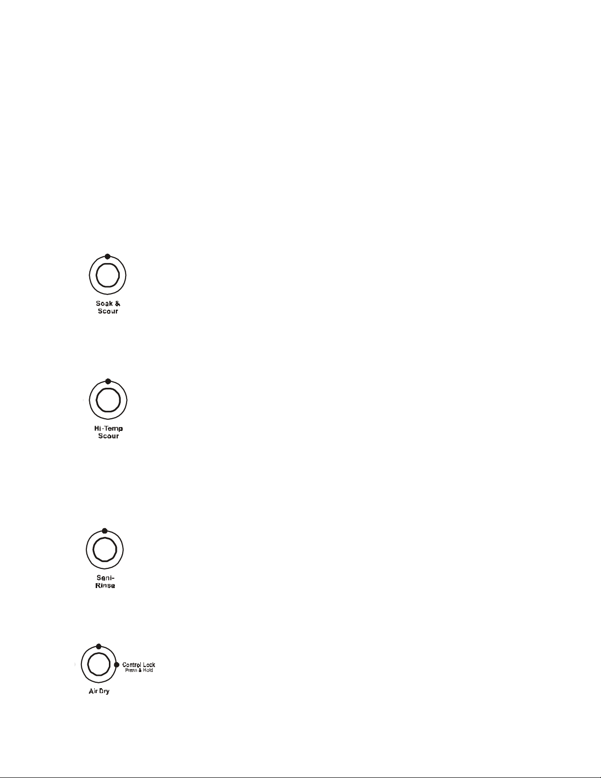
Soak & Scour
Select this option to run a 4 hour pre-soak before the selected cycle. The pre-soak
consists of a standard fill, an initial 8 minute wash, then 13 wash pulses, each 90
seconds long with a 16 minute pause between pulses. This keeps the dishes wet
and soaking. At the conclusion of the pre-soak, the dishwasher drains and the
selected cycle begins.
NOTE: The Soak & Scour option is allowed with the Pots & Pans cycle only.
Hi-Temp Scour
Select this option to increase the target water temperature during the wash portion of
the cycle. Hi-Temp Scour raises this target water temperature to 145° F (63° C) in the
Main Wash for all cycles. In the Pots & Pans cycle, Hi-Temp Scour also raises the
target water temperature to 135° F (57° C) in the pre-wash. Heating the
water helps improve washing results. Hi-Temp Scour is useful when loads contain
baked-on food.
This option adds heat, water and wash time by adding at least one additional rinse mode to the cycle.
NOTE: Hi-Temp Scour is an option with Pots & Pans and Normal.
Sani-Rinse
Select this option to raise the water temperature in the final rinse to approximately
160° F (70° C) for 10 minutes. Sani-Rinse adds heat and time to the cycle. In the
Normal cycle, this high temperature rinse sanitizes the dishes and glassware in accordance with the NSF International requirements (#95/480/05/2480).
NOTE: Sani-Rinse is an option with the Pots & Pans and Normal cycles.
Air Dry
Select this energy-saving option to dry without heat. Air drying is useful when loads
contain plastic dinnerware that may be sensitive to high temperatures. The dishes
take longer to dry and spotting can occur. For best drying, use a liquid rinse aid.
Some items, such as plastics, may need towel drying.
NOTE: Rinse Only does not have a dry period. Air Dry is an option with all other cycles.
5
Page 10
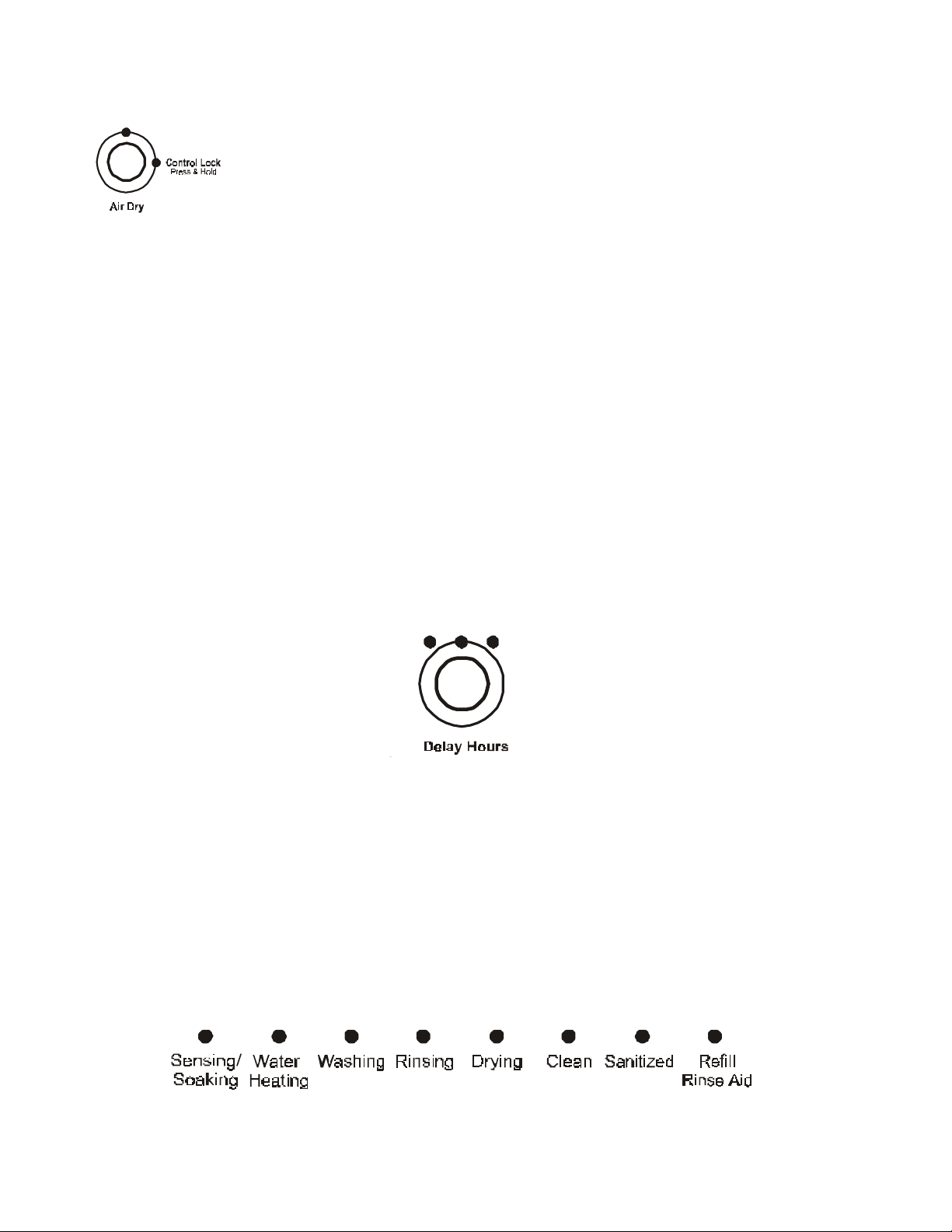
Control lock
Use the Control Lock to prevent the dishwasher from accidentally being turned on. Use
the ControlLock, also, to prevent accidental cycle or option changes during a cycle.
When the Lock LED is lit, all buttons are disabled.
NOTES:
• The dishwasher door can be opened while the controls are locked.
• The lock can be turned on while the dishwasher is running.
To Turn on the Control Lock:
Press and hold Air Dry for four (4) seconds. The LOCK LED will glow.
To Turn off the Lock:
Press and hold Air Dry for 4 seconds. The LED turns off.
Delay Hours
Select this option to run the dishwasher at a later time or during off-peak hours.
To Delay the Start:
1. Close the door.
2. Press Delay Hours 1 time for a 2-hour delay, 2 times or a 4-hour delay or 3 times for an 8hour delay .
3. Select a wash cycle and options.
The number glows above Delay Hours. The dishwasher starts the cycle in the selected number of
hours.
NOTE: T o cancel the delay and begin cycle immediately , press Delay Hours until all delay hours LEDs
are off.
248
Cycle Status Indicators
The progress of the dishwashing cycle can be followed with the Cycle Status Indicators.
6
Page 11
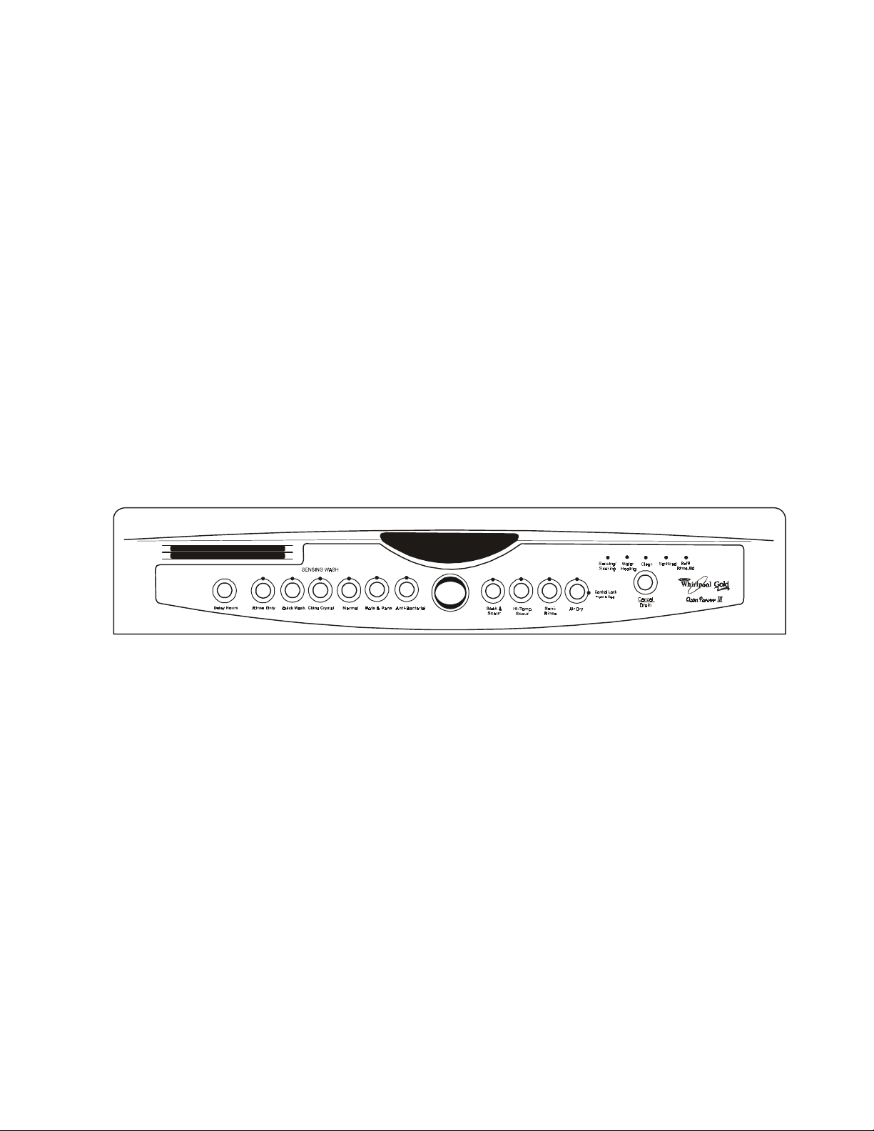
Sensing/Soaking
The dishwasher senses the soil level on the dishes. Soil level determines the length of some cycles,
the amount of heat added to the wash and the number of rinses needed in the cycle for the load. It also
senses the temperature of the water during thermal hold water heating periods. SENSING/SOAKING
glows during the soil sensing and thermal hold portions of the cycle. Wash action continues while
sensing occurs. SENSING/SOAKING also glows during “soaking” events and the 4-hour pre-soak
cycle invoked by the Soak & Scour Option.
Sanitized
If the Sani Rinse option is selected, SANITIZED glows when the Sani Rinse cycle is finished. If the
dishwasher did not properly sanitize the dishes, the light flashes at the end of the cycle. This can
happen if the cycle is interrupted or the dishwasher failed to reach sani temperatures. The light goes
off when any key is selected or the door is opened and reclosed.
Clean
CLEAN glows when a cycle is finished. The light turns off when the door is opened and reclosed or any
key is pressed.
CONTROL PANEL
MODEL: GU1500XTK
CYCLES
OPTIONS
CYCLE SELECTION CHART
Select the wash cycle and options desired. Upon selecting the cycle key , the cycle will begin immediately . Cycles may be changed at any time, during the first fill. Options can be selected or changed at
any time.
NOTE: The last options used will be recalled from memory automatically upon selecting a cycle, (if
the option is valid with the cycle selected).
A “ ” shows what steps are in each cycle.
•
Temperatures indicate where extra heat is added.
Water usage is shown in U.S. gallons/liters.
Cycle time includes dry time. An asterisk (*) by the cycle time indicates the cycle time might be longer
depending on the temperature of the water entering the dishwasher. The cooler the water, the longer
the cycle time. If the water is already hot enough, the cycle time will be as shown.
7
Page 12
High
Rinse
High
Low
High
Low
Low
Purge
Rinse
High
Low 130 F
(54 C)
º
º
8
Page 13
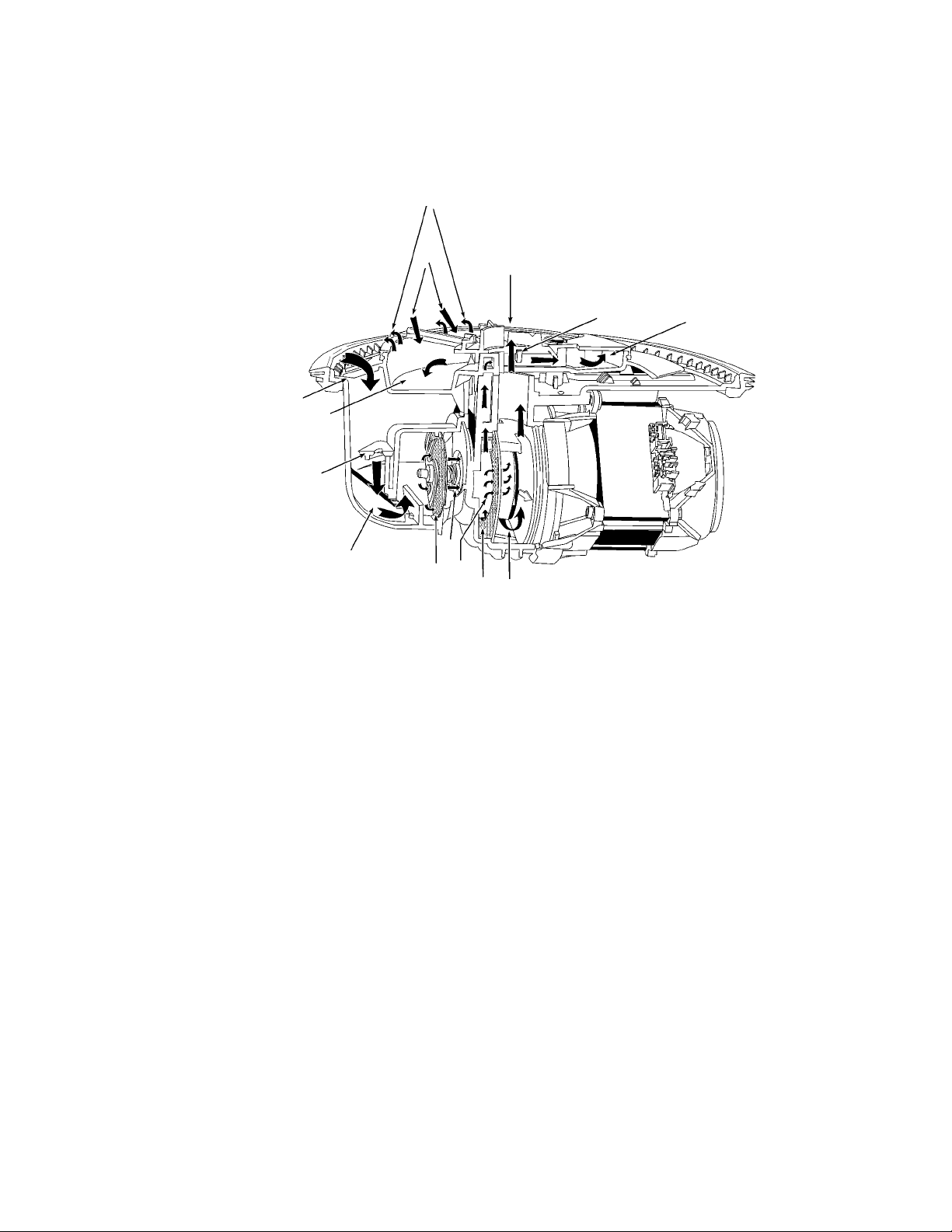
FUNCTION DESCRIPTION
The washing action of the Point Voyager Dishwasher performs more work and maintains higher performance with reduced energy consumption. This is accomplished with the following: 1) A redesigned
wash system using separate wash and drain pumps. 2) A soil sensor and thermistor which monitor
washing conditions. 3) An electronic control board which adjusts cycle functions to optimize washing
performance.
8
10
2a
7
2b
2c
4
6b
3
Wash/Rinse Function
1. The main wash water passes from the
spray arm nozzles, over the dish load and
into the sump assembly, where a number
of operations occur.
2. Water and soils pass through the course
protection grate at the top of the sump assembly (2a) and then passes through the
foreign object protector (2b) into the main
wash pump inlet chamber (2c).
3. The water then passes through the chopper assembly where food particles are reduced in size so they can pass through
the water delivery system. (3)
4. Water is drawn through the impeller and
into the pump chamber. (4)
5. Here, 20 percent of the water is diverted
towards the soil accumulator. Food soils
in this water stream are captured by the
separation screen. (5)
6. Downstream restrictions limit the water
flow into the accumulator to 10 percent.
11
6a
5
11
7
(6a) The remaining water is allowed to
rejoin the main wash flow by passing
through the separation screen. (6b)
7. This heavily soiled water is distributed
throughout the accumulator. (7) Soils will
remain trapped in the accumulator until a
drain or Automatic Purge Filtration event
takes place.
8. Since the water in the accumulator is under some minimal pressure, it rejoins the
main wash water by flowing through the
accumulator screen into the tub. (8)
9. For this to occur properly it is critical that
the dishwasher be installed perfectly level.
10. Jets located on the underside of the lower
spray arm continuously wash down the accumulator screen to allow more soils to
concentrate. (10)
11. The remaining 80 percent of the wash
water will flow from the impeller through
the volute and up through the spray arms.
(11)
9
Page 14
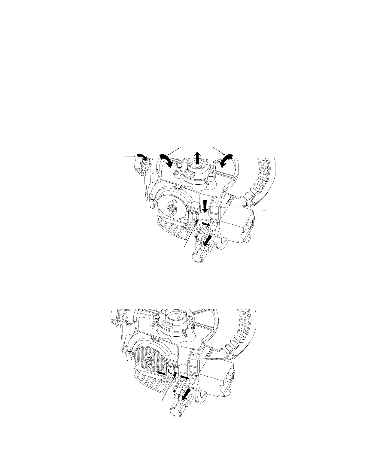
Drain Function
1. During the Drain function, a separate drain pump motor is started while the main wash pump
motor continues to operate for 1 minute. (1) This accomplishes three goals.
2. First, the jets on the underside of the lower spray arm continue to flush soils from the accumulator screen while the water is drained from the unit. (2)
3. Second, negative pressure in the main wash pump inlet chamber keeps the check valve closed,
allowing the drain pump to remove soiled water from the accumulator. (3)
4. Third, the spray arms will rinse down the interior of the wash tub while the water is drained,
leaving the inside free of soils. (4)
2
4
3
2
1
5. The main wash pump then stops creating positive pressure in the pump’s inlet chamber. This
opens the check valve allowing the remaining water to be drained away. (5)
5
10
Page 15
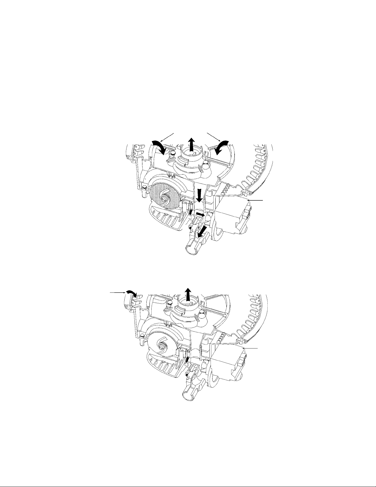
Automatic Purge Filtration
1. The Automatic Purge Filtration feature may be invoked if the soil sensor detects excessive
soils. This can occur during selected wash or rinse functions. APF mode provides one or
more purges of excess soils trapped in the soil accumulator at specified intervals in a cycle.
2. The APF mode operates for a total of 10 seconds while the wash pump is operating in a wash
or rinse mode. The accumulator screen will be cleaned from jets on the underside of the lower
spray arm. (2)
3. During the first five seconds, the drain pump turns on and the fill valve is activated. This
purges the soiled water from the accumulator and begins to add fresh water. (3)
2
2
APF Function
First Five Seconds
3
4. For the remaining five seconds, the drain pump is turned off, (4a) but the fill valve remains
activated to bring wash water up to the proper level. (4b)
4b
APF Function
Last Five Seconds
4a
Theory Resources
The tech sheet, found behind the access panel provides a Common Cycle Time Chart. This chart will
allow the service technician to identify and track each operation of the dishwasher by timed interval.
See Section Four, Troubleshooting and Diagnosis for instruction on how to use this chart with the
Diagnostic Routines built into the electronic controls of the dishwasher.
11
Page 16

-- NOTES --
12
Page 17
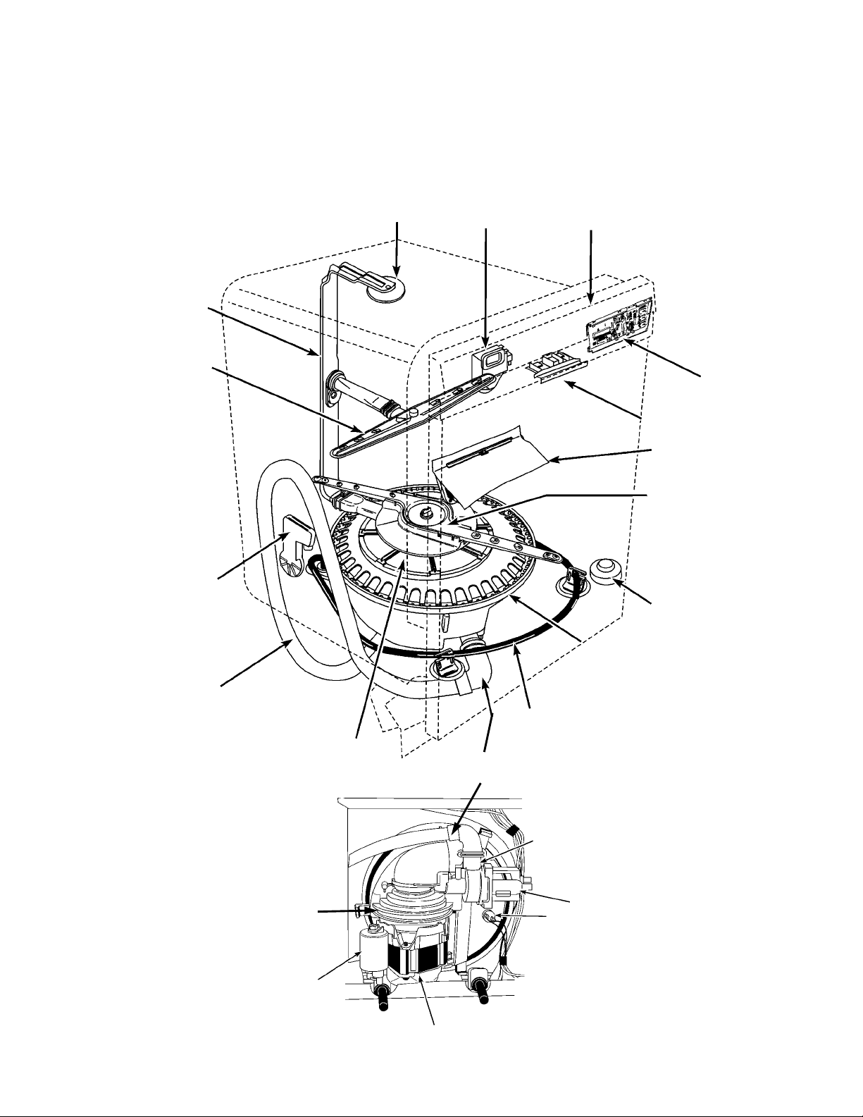
Inner Feed Tube
Middle Spray
Arm
SECTION THREE
COMPONENT ACCESS
COMPONENT LOCATION
Upper
Spray
Arm
Active
Vent
Control
Panel
Electronic
Control Board
(Interconnect
Board Underneath)
Door Latch Assembly
Dispenser
Assembly
LowerSpray Arm
Water Inlet
Drain Tube
Accumulator
Wash Pump
Start Capacitor
Float
Sump and Motor
Assembly
Heating
Element
Check Valve
(in drain hose)
Soil Sensor
Pressure Switch
Drain Pump Motor
Thermistor
Wash Pump Motor
13
Page 18
! IMPORTANT
Electrostatic Discharge (ESD) Sensitive Electronics
ESD problems are present everywhere. ESD may damage or weaken the electronic control assembly. The new control assembly may appear to work well after repair is finished, but failure may
occur at a later date due to ESD stress.
• Use an antistatic wrist strap. Connect wrist strap to green ground connection point or unpainted metal in the appliance. - OR - Touch your finger repeatedly to a green ground connection point or unpainted metal in the appliance.
• Before removing the part from its package, touch the antistatic bag to a green ground connection point or unpainted metal in the appliance.
• Avoid touching electronic parts or terminal contacts; handle electronic control assembly by
edges only.
• When repacking failed electronic control assembly in antistatic bag, observe above instructions.
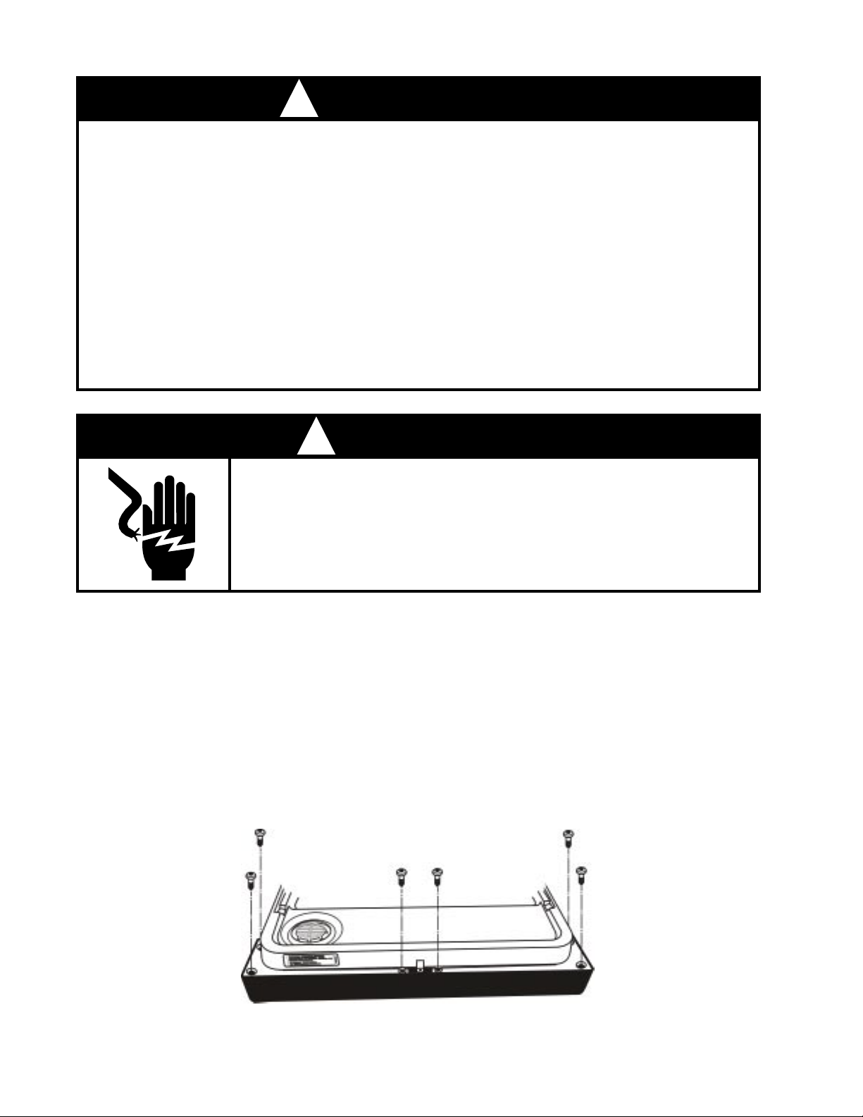
! WARNING
ELECTRICAL SHOCK HAZARD
Disconnect power before servicing the dishwasher.
Replace all panels before operating the dishwasher.
Failure to do so can result in death or electrical shock.
ACCESSING COMPONENTS IN THE DOOR
Removing the Console Panel
The control panel on the Voyager Dishwasher can be removed from the dishwasher door.
1. Remove the six (6) screws securing the control panel to the door frame. (Fig. 3-1)
2. The control panel will now drop down and be free of the door assembly. The wiring harness
will remain connected to the console components.
Fig. 3-1
14
Page 19
Removing the Electronic Control Board
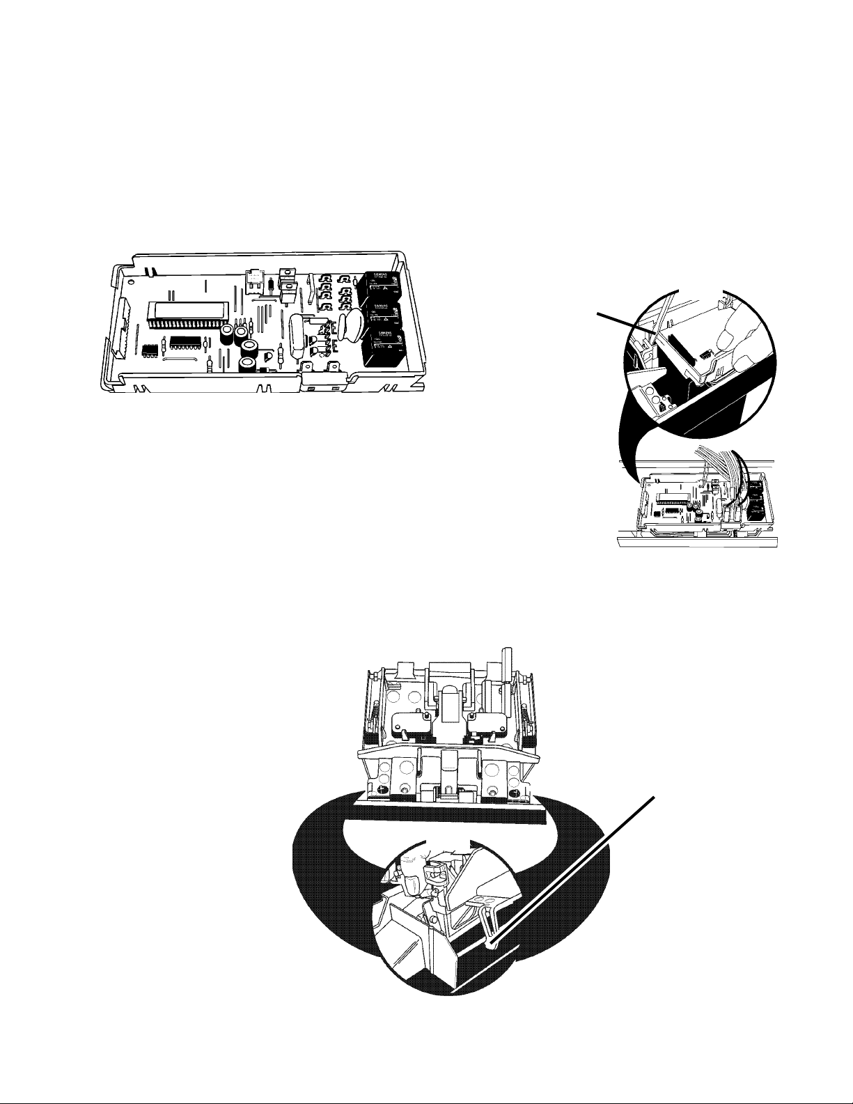
The electronic control board is located inside the console at the top of the dishwasher door.
1. Disconnect the ribbon connector and the wiring harness connectors from the electronic control
board. (Fig. 3-2)
2. Use a flat bladed screwdriver to depress the holding tabs at the left end of the control board
assembly while pulling up. (Fig. 3-3, Inset)
Use a flat bladed
screwdriver to depress
the holding tabs
at the left end
of the control board
assembly while pulling
up as shown here.
Fig. 3-3
Fig. 3-2
Inset
Removing the Door Latch Assembly
Release the tabs securing the door latch assembly to the control panel and lift the assembly out. (Fig.
3-4, Inset)
Tab
Inset
Fig. 3-4
15
Page 20
Removing the Door Microswitches
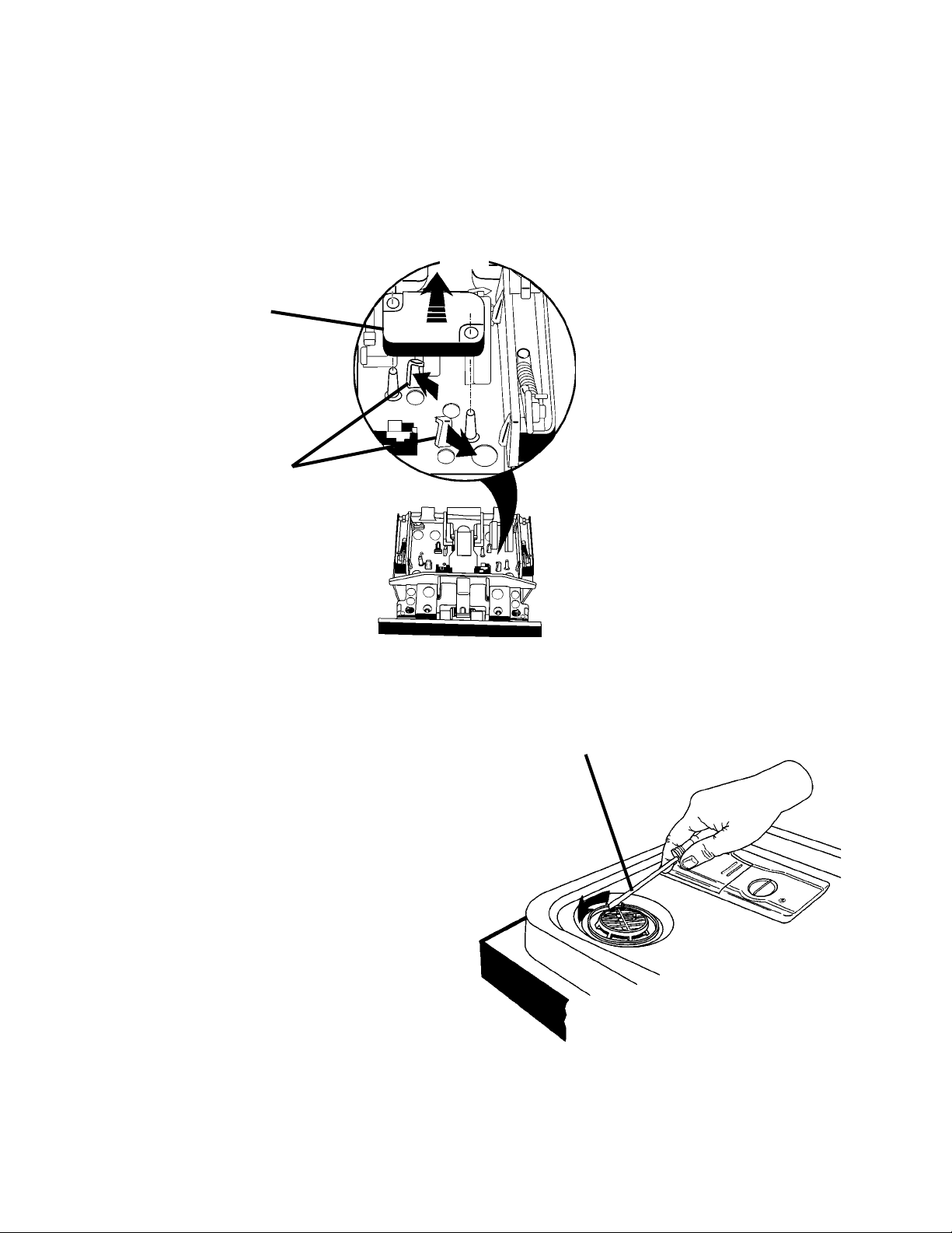
The Door Switches are located on the right and left side of the door latch assembly.
1. Disconnect the wiring harness connectors from the microswitch terminals.
2. Pull back on the two (2) plastic retaining tabs securing the microswitches to the door latch
assembly and lift the microswitches out. (Fig. 3-5)
Inset
Lift Microswitch
Spread Tabs
(Caution: These
tabs can break.)
Removing the Active Vent
Fig. 3-5
Assembly
The Active Vent Assembly is located in the console area.
1. Remove the six (6) screws securing the
control panel to the door frame.
2. Disconnect the wiring harness connectors
from the wax motor terminals on the active vent assembly .
3. Loosen, but do not remove the four T-15
Torx screws securing the left side of the
outer door panel to the door frame. This
will provide additional room to easily re
move the active vent assembly.
4. Using a flat bladed screwdriver in the slot
provided at the bottom of the interior vent
grille, turn the vent grille counterclockwise
¼ turn and remove the grille. (Fig. 3-6)
Use Flat Bladed
Screwdriver and Turn
Interior Vent Grille ¼ Turn
Counter-clockwise
Fig. 3-6
5. The active vent assembly will drop free of
the dishwasher door.
16
Page 21
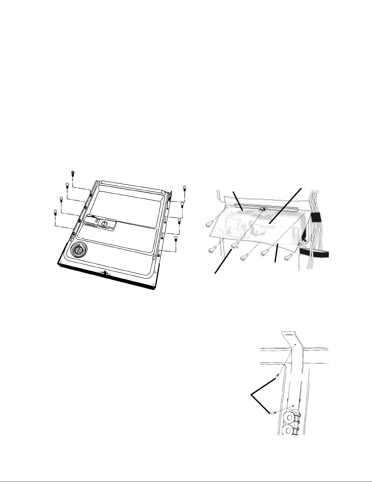
Removing the Dispenser Assembly
The Dispenser Assembly is located in the lower portion of the dishwasher door below the console
area.
1. Remove the eight (8) screws securing the outer door panel to the dishwasher door frame.
(Fig. 3-7) Remove the outer door panel from the door frame.
2. Remove the center top hex head screw and remove the dispenser shield and disconnect the
wiring harness connectors from the detergent dispenser solenoid.
(Fig. 3-8)
3. Remove the remaining five (5) screws securing the dispenser assembly to the inner door liner.
(Fig. 3-8)
4. Bend the two locking tabs at the top and bottom of the dispenser assembly up away from the
dispenser body.
5. The dispenser assembly can now be lifted from the inner door liner.
Dispenser
Tab
Shield
Fig. 3-7
SERVICING COMPONENTS INSIDE THE WASH TUB
Removing the Inner Feed Tube and
Lower Spray Arm
The Inner Feed Tube is held in place by two (2)
screws. (Fig. 3-9) One is located on the inner top
of the dishwasher tub. The second is located on
the back of the dishwasher tub.
1. Remove the two (2) dishracks from the
dishwasher tub.
2. Remove the two (2) screws securing the
Inner Feed Tube to the inside of the dish
washer tub.
Remove This
Screw First
Tab
Fig. 3-8
Screws
17
Fig. 3-9
Page 22
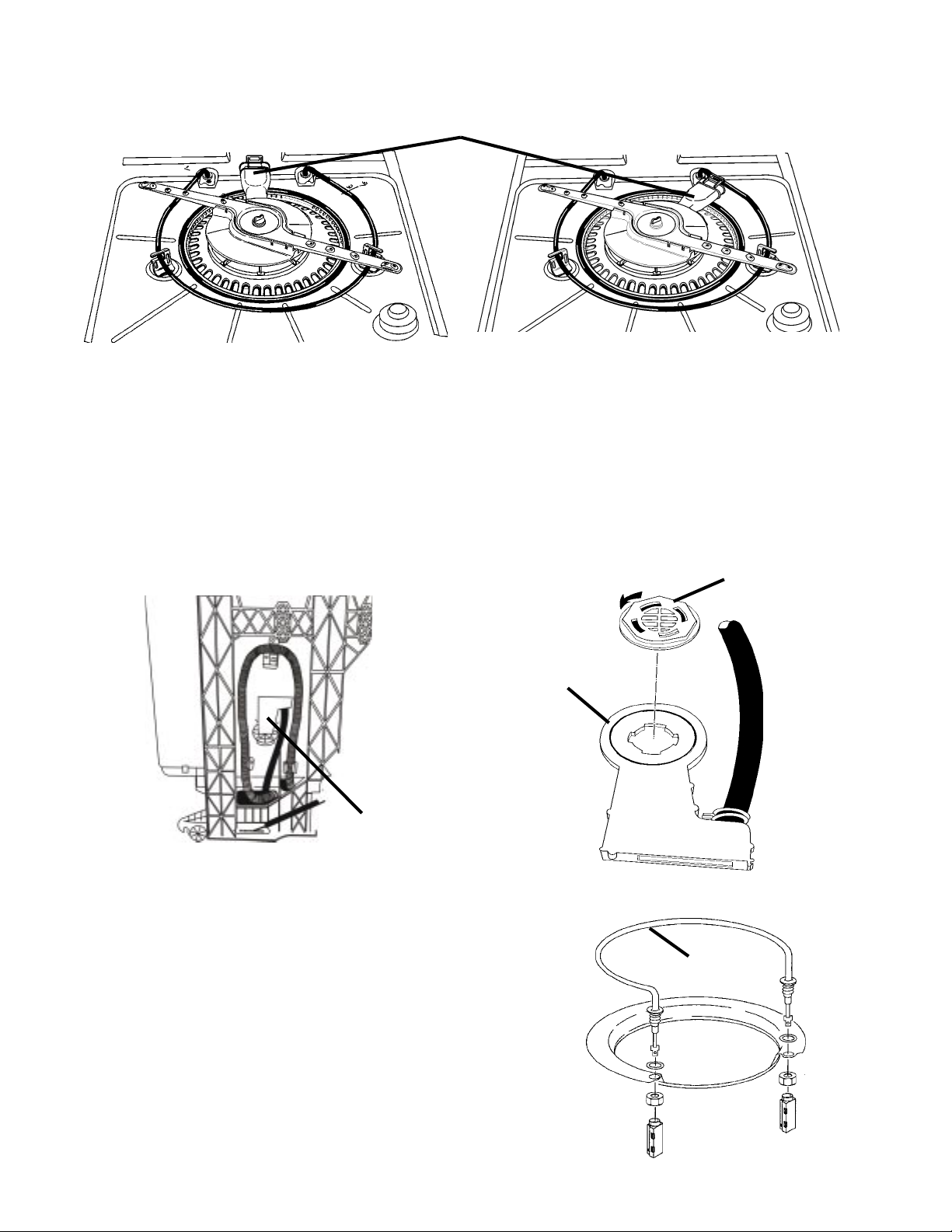
3. Rotate the rear feed cap (Fig. 3-10a) ¼ turn clockwise (Fig. 3-10b)
Rear Feed Cap
Fig. 3-10a
Fig. 3-10b
4. The entire inner water tube assembly and the lower spray arm assembly can now be removed
from the dishwasher tub.
Removing the Water Inlet
The water inlet is located on the left side of the dishwasher tub. (Fig. 3-11)
1. From the inside of the tub, use a small pair of Channel Locks™ and turn the inlet grille ¼
turn counterclockwise and remove the grille. (Fig. 3-12)
2. The water inlet can now be separated from the dishwasher tub.
Water Inlet
Water Inlet Grille
Water Inlet
Fig. 3-11
Servicing the Heating Element
The heating element (Fig. 3-13) should not be removed unless it has failed. All critical components
of the dishwasher can be removed without removing the heating element.
If the heating element must be removed, it must
be replaced with a new one.
When installing a new heating element, follow the
Installation Instructions provided with the new item.
Fig. 3-12
Heating Element
Fig. 3-13
18
Page 23
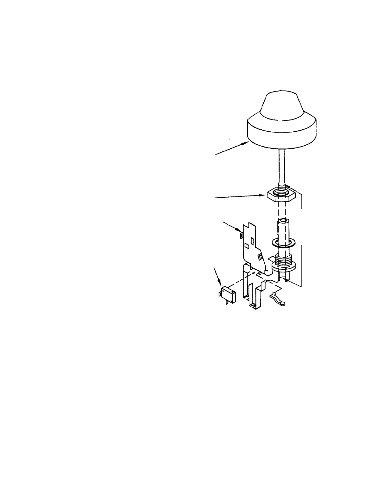
Servicing the Overfill Assembly
Removing the Float
The float (Fig. 3-14) can be removed from inside
the tub.
1. Tip the float slightly and gently toward the
back of the tub and lift up to disengage it
from the overfill assembly body .
Removing the Overfill Control Switch
The overfill control switch can be removed from
the overfill assembly without removing the assembly from the tub.
1. Remove the toe and access panels from
the bottom of the dishwasher.
2. Unsnap the cover over the overfill control switch.
3. Lift the overfill control switch from the assembly.
4. Disconnect the wiring harness connectors
from the switch terminals.
Removing the Overfill Assembly
1. Remove the toe and access panels from
the bottom of the dishwasher.
2. Remove the float.
3. Remove the standpipe nut.
4. Push the overfill assembly through the
bottom of the tub.
5. Open the cover and lift the overfill control
switch from the assembly.
Float
Standpipe
Nut
Overfill
Switch
Cover
Overfill
Control
Switch
Tip Float Slightly
Toward Back to
Disengage It from
the Overfill
Assembly Body
Overfill
Assembly
Fig. 3-14
6. Disconnect the wiring harness connectors
from the switch terminals.
19
Page 24
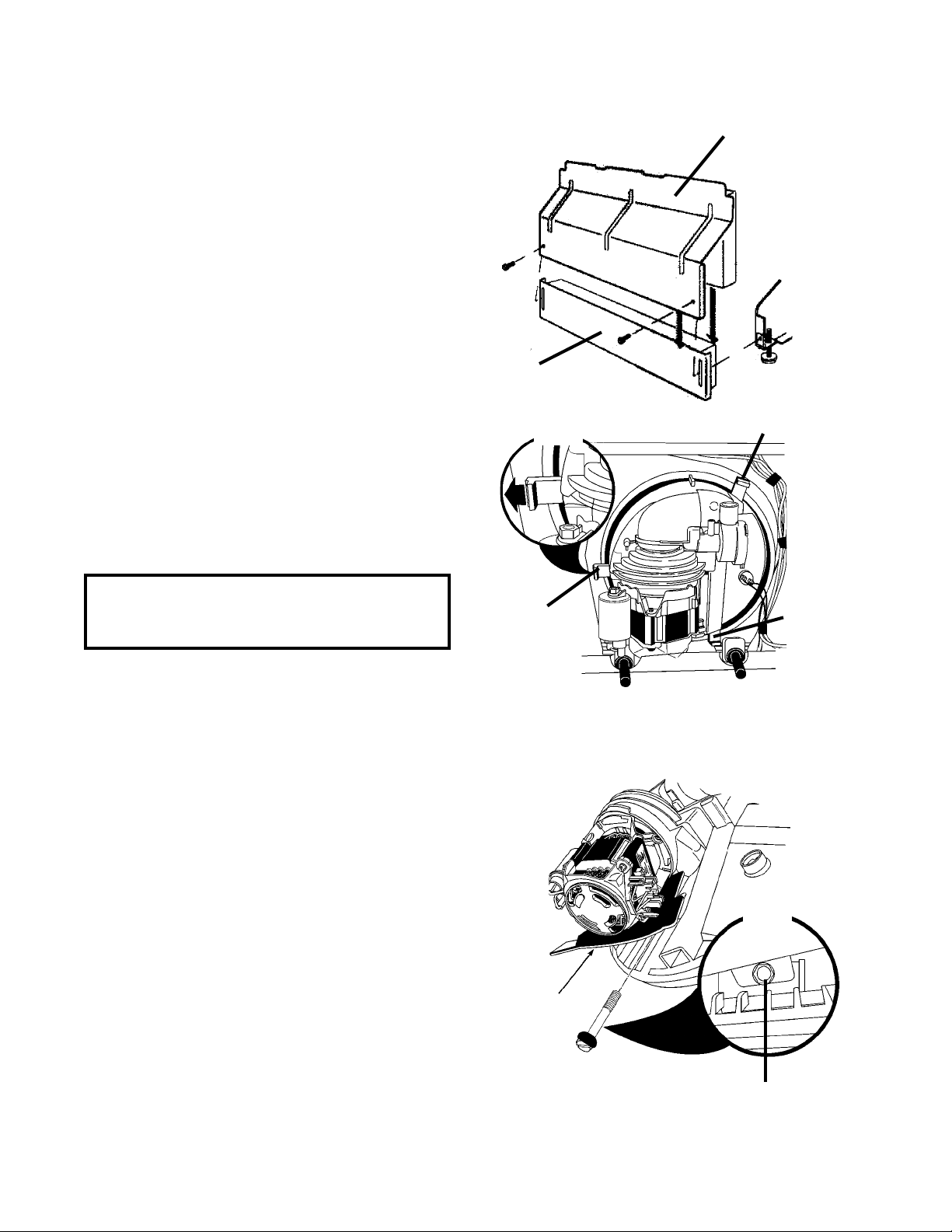
Removing the Pump Assembly
The entire pump assembly can be removed from inside the dishwasher tub.
1. Remove the access and toe panels from
underneath the dishwasher door by removing the two (2) screws securing it to
the dishwasher frame. (Fig. 3-15)
2. Disconnect the wiring harness connectors
from the drive motor and pump motor
terminals, the soil sensor and the thermistor.
3. Disconnect the drain hose from the drain
hose connector on the pump outlet.
4. Remove the pump motor. (See next
Toe Panel
page.)
Fig. 3-15
5. Remove the three (3) sump tabs that
Inset
secure the sump assembly to the dishwasher tub. (Fig. 3-16, Inset)
6. From inside the tub, lift the front of the
sump up approximately ½ inch.
Push the assembly back and then lift it out.
Access Panel
Sump Tab
NOTE: When reinstalling the sump assembly,
align the locator key with the corresponding
slot in the tub opening.
SERVICING COMPONENTS IN THE SUMP ASSEMBLY
Removing the Wash Motor
1. Remove the bolt securing the wash
motor and drip shield in place on the pump
assembly. (Fig. 3-18)
2. Once the bolt and drip shield are removed,
turn the wash motor until it stops (approximately ¼ turn).
3. Pull the motor straight back from the sump
assembly . Some effort may be necessary
to dislodge the motor. The volute will remain attached to the motor. (See Figure
3-29)
Sump Tab
Drip Shield
Sump
Tab
Fig. 3-16
Inset
NOTE: When reinstalling the wash motor and
volute, do not pinch the volute seal between the
volute and sump. Use a small amount of rinse
aid on the volute seal to help installation.
20
Fig. 3-17
Bolt Holds Drip
Shield in Place
Page 25
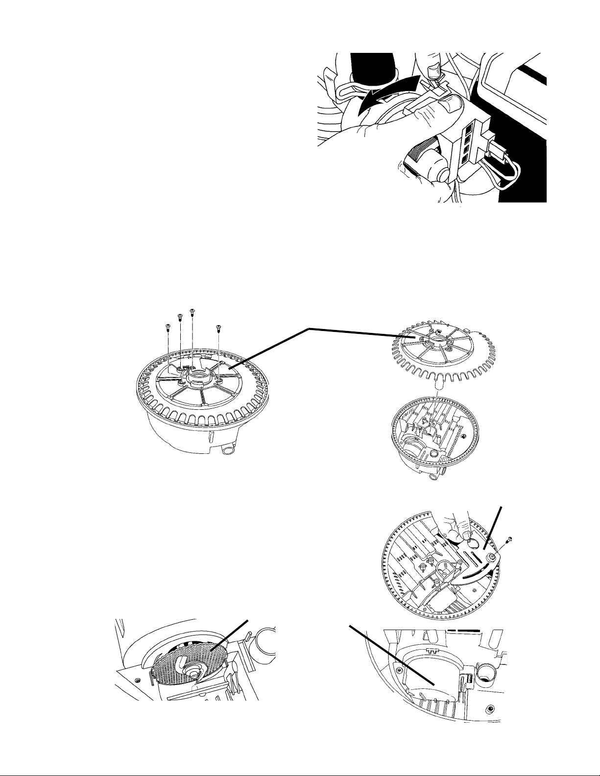
Removing the Pump Motor
1. With one hand, press back on the plastic
tab that holds the pump motor from rotating. (Fig. 3-18)
2. With the other hand, rotate the pump motor counterclockwise approximately ¼
turn. The pump motor will now be free of
the pump assembly.
Fig. 3-18
Accessing Components of the Sump Assembly
Components inside the sump can be accessed without removing the sump from the dishwasher tub.
1. Remove the four (4) screws securing the soil accumulator from the sump base. (Fig. 3-19)
2. The soil accumulator will now lift free of the sump base. (Fig. 3-20)
Accumulator
Fig. 3-19
3. Remove the screw securing the foreign
objects protector to the sump base and
remove the protector. (Fig. 3-21)
4. Remove the screw securing the inlet protector to the pump base and lift the inlet
protector out. (Fig. 3-22)
5. Remove the chopper assembly from the
impeller shaft and lift it from the sump
base. (Fig. 3-23)
Chopper
Fig. 3-23
21
Fig. 3-21
Inlet
Protector
Fig. 3-22
Fig. 3-20
Foreign
Object
Protector
Page 26
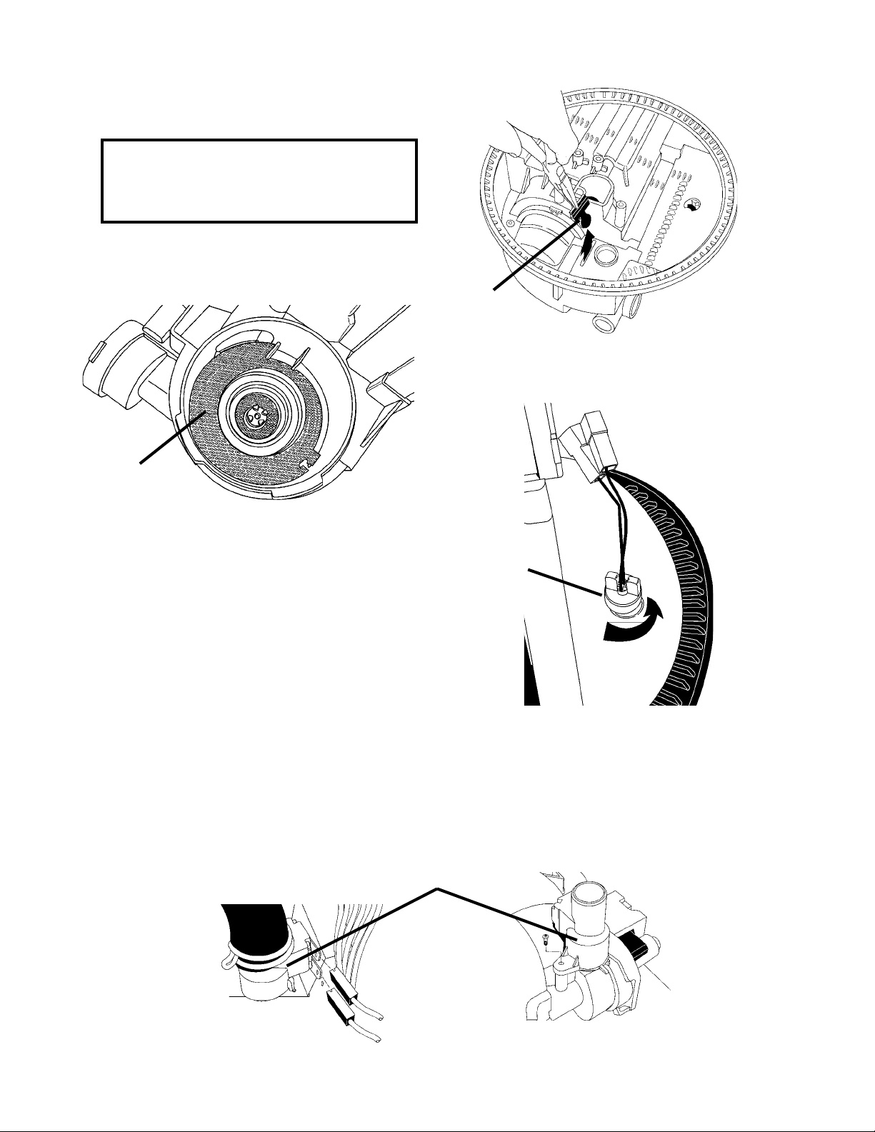
6. The check valve, located between the
wash motor and the drain can be removed
with a pair of needle nose pliers. (Fig. 3-24)
NOTE: When replacing the check valve,
simply drop it in place. The inlet protector
will seat the flapper valve properly when it is
reinstalled.
7. With the wash motor removed, the separation
screen can be removed from the sump base.
(Fig. 3-25)
Separation Screen
Check
Valve
Fig. 3-24
Fig. 3-25
8. The thermistor can be removed from the sump
Thermistor
by turning it ¼ turn counterclockwise and
pulling it out. (Fig. 26) The thermistor can
be removed without removing the sump
assembly from the tub.
Access to the thermistor can be gained by
removing the access and toe panels while
the unit is in its installed position.
Fig. 3-26
Removing the Soil Sensor
If so equipped, a soil sensing pressure switch is mounted on the pump outlet. Disconnect the two
wiring harness connectors from the switch terminals. Disconnect the drain hose. (Fig. 3-27A) Remove the screw securing the sensor switch to the pump base. Lift it from the pump outlet. (Fig. 3-27B)
Soil Sensor
Pressure Switch
Fig. 3-27A
Fig. 3-27B
22
Page 27
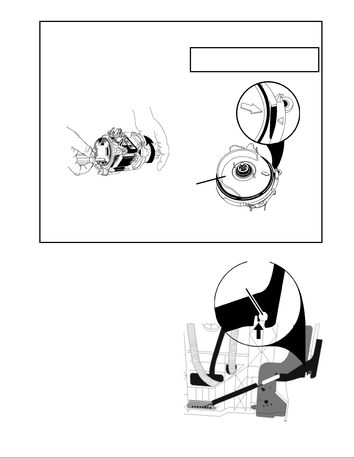
Removing the Impeller from the Wash Motor
The impeller is attached to the wash motor and can
be removed once the wash motor is removed from
the pump base.
1. Place the end of a flat-bladed screwdriver
into the back of the wash motor to hold the
armature of the motor from turing while unscrewing the impeller clockwise. (Fig. 3-28)
Take care not to scratch or nick the motor
windings.
Do not touch sealed surfaces on the
impeller or the volute. Contamination or
damage will cause premature failure.
Fig. 3-28
To Remove the Volute
1. Align the arrow on the volute and the
locator triangle on the wash motor
frame as in Figure 3-29.
2. Lift the volute from the wash motor.
SERVICING THE DOOR HINGE
To service the door hinge the dishwasher must
be removed from its installed position. Be sure
to:
• Disconnect power from the unit.
• Disconnect the water supply line from the
unit.
• Disconnect the drain line from the unit.
Once the side of the dishwasher is accessible:
1. Remove the outer door panel and console
from the dishwasher door.
Volute
Fig. 3-29
INSET
Hinge Pin
Fig. 3-30
2. Remove the door spring from the tension
adjustment at the bottom of the unit and then
remove the spring link from the door hinge
plate (Fig. 3-30).
3. Using a pair of pliers, slightly bend the tab
on the door hinge plate to open the slot for
the hinge pin. (Fig. 3-30, INSET- Arrow points
at tab).
23
Page 28
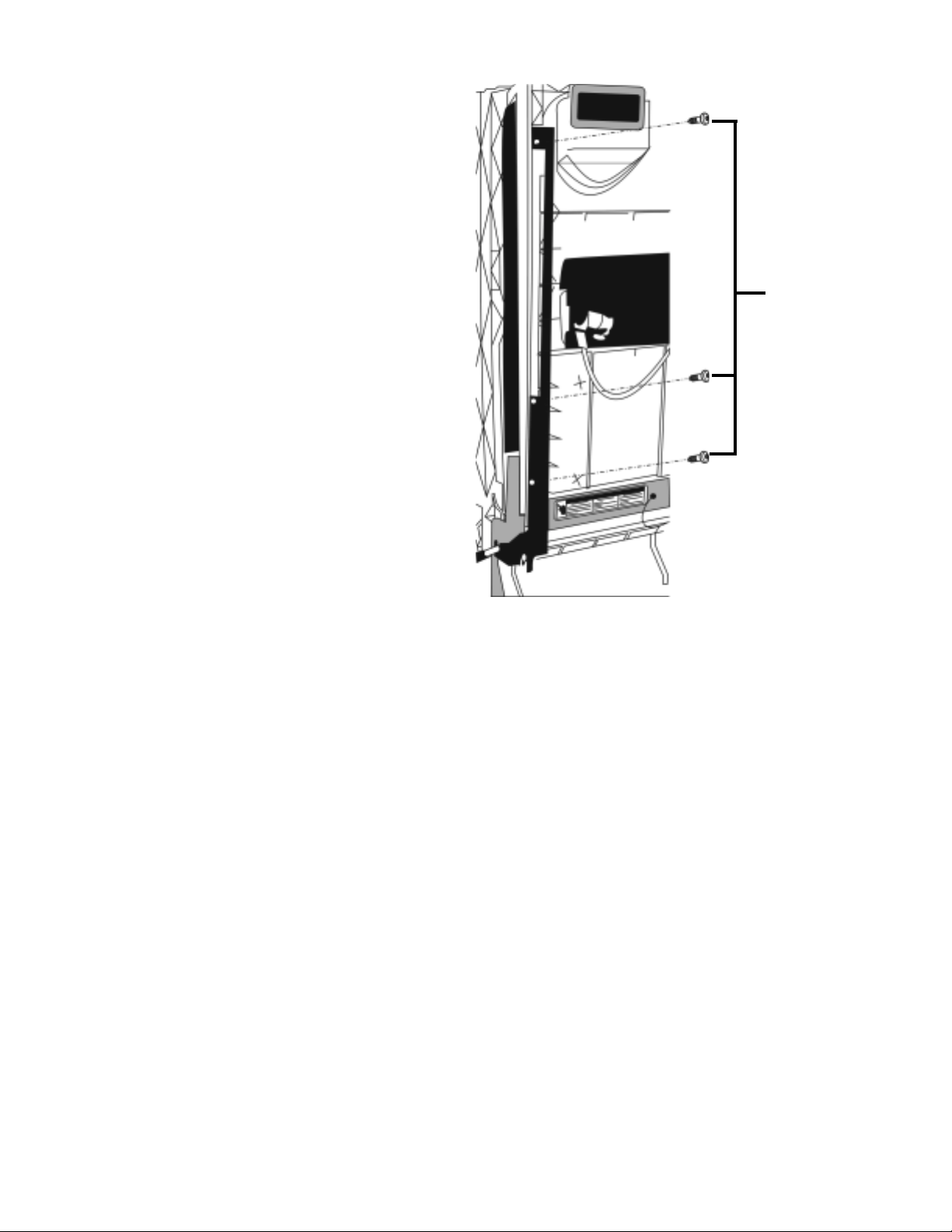
4. Remove the three (3) screws securing the
hinge plate to the front of the dishwasher
inner door panel. (Fig. 3-31)
5. Open the door slightly . Hold onto the door
assembly . With the counterbalance spring
removed, the door will drop open easily .
6. Lift the door up to disengage it from the
hinge pin (Fig. 3-30, INSET) and then
carefully pull the hinge plate from the inner door panel.
SCREWS
Fig. 3-31
24
Page 29

SECTION FOUR
TROUBLESHOOTING AND DIAGNOSIS
TROUBLESHOOTING CHART
PROBLEM POSSIBLE CAUSES CORRECTION/TEST
Dishwasher does not run
or stops during a cycle
Dishwasher will not fill
1. Door is not latching properly.
2. Child lock is "ON".
3. Wash Cycle not set properly.
4. Household fuse blown or circuit
breaker tripped.
5. Dishwasher is not wired into a
circuit with proper voltage.
1. Overflow protection float is
stuck in "up" position.
2. Fill valve is inoperable.
3. Control board is inoperable.
1. Check to make sure handle
is properly seated in door
latch assembly. Check that
the door switch is opening
and closing properly.
2. Turn child lock "OFF". See Use
and Care Guide.
3. Review setting Wash Cycles
in the Use and Care Guide.
4. Have a qualified electrician
check the circuit breaker or
fuse.
5. Have customer call a qualified
electrician.
1. Check that the overflow protection float is free to move
"up" and "down" Check that
the overfill switch in opening
and closing properly.
2. Check for continuity between
contacts on fill valve.
3. Check for 120VAC between
P8 and P2-3.
Dishwasher will not drain
Dishwasher will not
dry dishes
1. Air gap (if installed) is clogged.
2. Pump motor is inoperable
3. Control board is inoperable.
1. Heater element burned out.
2. Hi-Limit thermostat inoperable.
3. Active vent wax motor inoperable.
1. Follow air gap manufacturer's
directions for cleaning.
2. Disconnect pump motor from
wiring harness and check for
continuity between GY &BU/
BK.
3. Check for 120VAC between
P8 and P3..
1. • Check for continuity between the terminals of the
heater element.
• Check for 120VAC between
P8 and Neutral.
2. Check for continuity between
terminals of the hi-limit
thermostat.
3. • Check for continuity between terminals of the
wax motor.
• Check for 120VAC between
P8 and Neutral.
25
Page 30
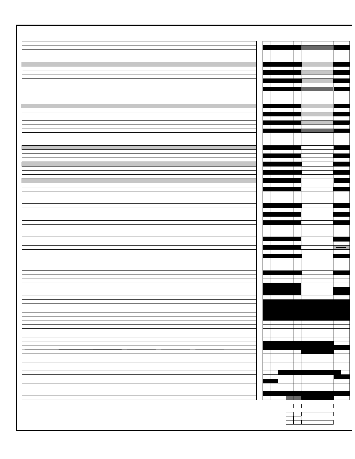
COMMON CYCLE TIME CHART
INTERVAL 45 44 43 42 41 40 39 38
ANTI-BACTERIA / BAKED-ON COOKWARE NOTES 1A,14A,15,16
INTERVAL TIME (min:sec) THERMAL HOLD
WITH HI TEMP SCRUB OPTION — ANY SOIL LEVEL NOTE 14A 99:00 w/o Th.Holds [135F / 57C]
NUMERIC DISPLAY CYCLE TIME (spinning “CLOCK” pattern in INTERVALS 45-42 for some models, see NOTE 5) [99] [98] [98] [98] 94 92 92 91
HIGH SOIL [Soil sensed in Interval 42] NOTE 1A 99:00 w/o Th.Holds [130F / 54C]
NUMERIC DISPLAY CYCLE TIME (spinning “CLOCK” pattern in INTERVALS 45-42 for some models, see NOTE 50 [99] [98] [98] [98] 94 92 92 91
LOW SOIL (or Non-Sensor Model) [No soil sensed in Interval 42] NOTE 1A 91:25 w/o Th.Holds [130F / 54C]
NUMERIC DISPLAY CYCLE TIME (spinning “CLOCK” pattern in INTERVALS 45-42 for some models, see NOTE 5) [99] [98] [98] [98] 86 84 84 83
POTS & PANS / HEAVY NOTES 1A,14A,15,16
INTERVAL TIME (min:sec) THERMAL HOLD
WITH P.SCOUR / H.T.SCRUB OPTION — ANY SOIL LEVEL NOTE 14A 97:00w/o Th.Holds [135F / 57C]
NUMERIC DISPLAY CYCLE TIME (spinning “CLOCK” pattern in INTERVALS 45-42 for some models, see NOTE 5) [97] [96] [96] [96] 92 90 90 89
HIGH SOIL [Soil sensed in Interval 42] NOTE 1A 97:00w/o Th.Holds [130F / 54C]
NUMERIC DISPLAY CYCLE TIME (spinning “CLOCK” pattern in INTERVALS 45-42 for some models, see NOTE 5) [97] [96] [96] [96] 92 90 90 89
LOW SOIL (or Non-Sensor Model) [No soil sensed in Interval 42] NOTE 1A 89:25 w/o Th.Holds [130F / 54C]
NUMERIC DISPLAY CYCLE TIME (spinning “CLOCK” pattern in INTERVALS 45-42 for some models, see NOTE 5) [97] [96] [96] [96] 84 82 82 81
NORMAL NOTES 1A,9,14B,15,16
INTERVAL TIME (min:sec)
HIGH SOIL WITH P.SCOUR / H.T.SCRUB OPTION [Soil sensed in Interval 42] NOTE 14B 95:00 w/o Th.Holds
NUMERIC DISPLAY CYCLE TIME (spinning “CLOCK” pattern in INTERVALS 45-42 for some models, see NOTE 5) [95] [94] [94] [94] 90 88 87
HIGH SOIL [Soil sensed in Interval 42] NOTE 1A 95:00 w/o Th.Holds
NUMERIC DISPLAY CYCLE TIME (spinning “CLOCK” pattern in INTERVALS 45-42 for some models, see NOTE 5) [95] [94] [94] [94] 90 88 87
LOW SOIL (or Non-Sensor Model) H.T.SCRUB OPTION [No soil sensed in Interval 42] NOTE 14B 87:25 w/o Th.Holds
NUMERIC DISPLAY CYCLE TIME (spinning “CLOCK” pattern in INTERVALS 45-42 for some models, see NOTE 5) [95] [94] [94] [94] 82 80 79
LOW SOIL (or Non-Sensor Model) [No soil sensed in Interval 42] NOTE 1A 87:25 w/o Th.Holds
NUMERIC DISPLAY CYCLE TIME (spinning “CLOCK” pattern in INTERVALS 45-42 for some models, see NOTE 5) [95] [94] [94] [94] 82 80 79
LOW SOIL (or Non-Sensor Model) [No soil sensed in Interval 42] — E. STAR MODEL NOTE 1A 78:20 w/o Th.Holds
NUMERIC DISPLAY CYCLE TIME (spinning “CLOCK” pattern in INTERVALS 45-42 for some models, see NOTE 5) [95] [94] [94] [94] 73 71 70
CHINA/LIGHT NOTES 1A,10,16
INTERVAL TIME (min:sec)
HIGH SOIL [Soil sensed in Interval 42] NOTE 1A 78:25 w/o Th.Holds
NUMERIC DISPLAY CYCLE TIME (spinning “CLOCK” pattern in INTERVALS 45-42 for some models, see NOTE 5) [79] [77] [77] [77] 73 71 70
LOW SOIL (or Non-Sensor Model) [No soil sensed in Interval 42] NOTE 1A 70:20 w/o Th.Holds
NUMERIC DISPLAY CYCLE TIME (spinning “CLOCK” pattern in INTERVALS 45-42 for some models, see NOTE 5) [79] [77] [77] [77] 65 63 62
QUICK CLEANUP / TIME SAVER NOTES 1B,11,1 6
INTERVAL TIME (min:sec)
COOL FIRST FILL [Sensed inlet water <135F in Interval 45] NOTE 1B 47:35
NUMERIC DISPLAY CYCLE TIME (spinning “CLOCK” pattern in INTERVALS 45-42 for some models, see NOTE 5) [48] [46] [46] [46] 46 45 44
HOT FIRST FILL [Sensed inlet water >135F in Interval 45] NOTE 1B 43:55
NUMERIC DISPLAY CYCLE TIME (spinning “CLOCK” pattern in INTERVALS 45-42 for some models, see NOTE 5) [48] [46] [46] [46] 42
RINSE ONLY NOTE 1C
INTERVAL TIME (min:sec)
ALL MODELS & CONDITIONS (No cycle changes based on sensor inputs) NOTE 1C 9:45
NUMERIC DISPLAY CYCLE TIME (spinning “CLOCK” pattern in INTERVALS 45-42 for some models, see NOTE 5) [10] [9] [9] [8] 4 2 1
RINSE ONLY” CYCLE PROGRESSION & STATUS INDICATORS [All other prog./status LED’s off]
SOAKING/SENSING NOTE 7
CIRC (PROG BAR R2) (This LED will be labeled as ‘WASHING’ on models that use it, but it is on during all Wash and Rinse Periods)
RINSING
“CYCLE PROGRESSION & STATUS INDICATORS
PROG BAR W1
PROG BAR W2
WASHING (PROG BAR W3)
PROG BAR R1
CIRC (PROG BAR R2) (This LED will be labeled as ‘WASHING’ on models that use it, but it is on during all Wash and Rinse Periods)
RINSING
DRYING
SOAKING NOTE 7
SOAKING/SENSING NOTE 7
ADD-A-DISH
WATER HEATING (THERMAL HOLD INDICATOR) NOTE 6
SANITIZED NOTE 8,15
CLEAN NOTE 8
OUTPUT LOADS
WASH MOTOR (MAIN WINDING)
DRAIN MOTOR NOTE 2 APF APF APF
FILL NOTE 2 APF APF APF
APF ENABLED INTERVALS -Max # of APF Purges allowed in Interval NOTE 2 max3 max2 max 2
DETERGENT / RINSE AID DISPENSER
VENT
HEATER NOTES 4,10,11,16
1:35
1:35
1:35
1:35
1:35
1:35
PERIOD 1
PRE-WASH
0:05
0:05
4:00
2:00
0:05
0:05
4:00
2:00
0:05
0:05
4:00
2:00
0:05
0:05
4:00
2:00
0:05
0:05
0:35
0:35
0:05
0:05
4:00
2:00
13
14 14
11 11
22 2
1:00
1:00
1:00
1:00
1:00
1:00
NOTES
1:00
1:00
1:00
1:00
1:00
>
1:00
26
Page 31
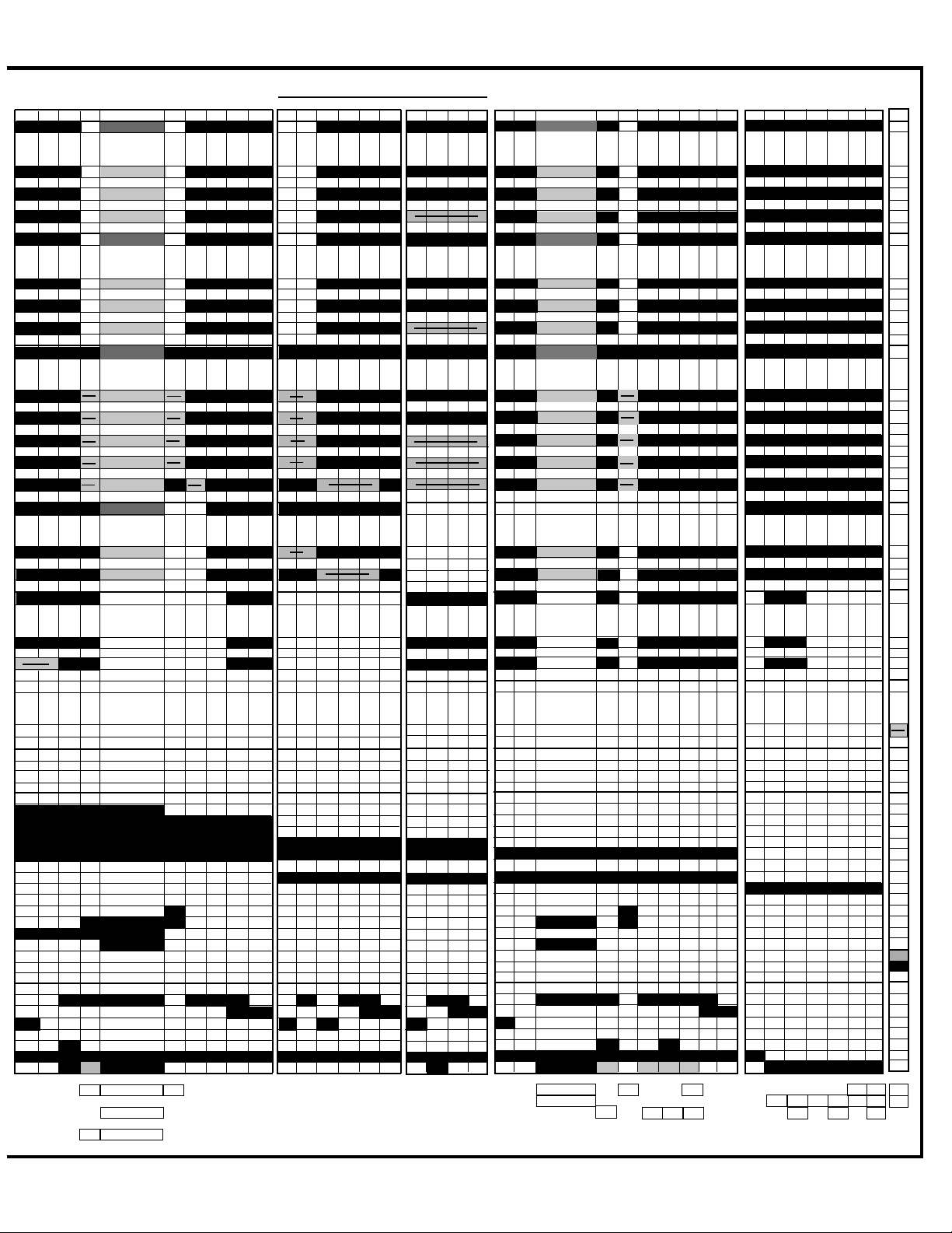
PERIOD 2
37 36 35 34 33 32 31 30 29 28
MAIN WASH
PURGE/RINSE
27 26 25 24 23 22
PERIOD 3
RINSE
21 20 19 18
PERIOD 4
17 16 15 14 13 12 11 10 9 8
FINAL RINSE
PERIOD 5
7654321
DRY
0
0:45
0:45
0:45
0:45
7:00
>
>
>
>
>
7:00
THERMAL HOLD
[145F / 63C]
[145F / 63C]
[145F / 63C]
THERMAL HOLD
[145F / 63C]
[140F / 60C]
[140F / 60C]
THERMAL HOLD
[145F / 63C]
[140F / 60C]
[145F / 63C]
[135F / 57C]
[120F / 49C]
THERMAL HOLD
[120F / 49C]
[120F / 49C]
0:05
1:35
90 88 88 87 87 67 63 62
90 88 88 87 87 67 63 62
82 81 80 80 80 60 56 55
0:05
1:35
88 86 86 85 85 67 63 62
88 86 86 85 85 67 63 62
80 79 78 78 78 60 56 55
0:05
1:35
86 84 84 83 83 67 63 62
86 84 84 83 83 67 63 62
78 77 76 76 76 60 56 55
78 77 76 76 76 60 56 55
69 67 67 67 60 60 56 52 51
0:05
1:35
69 68 67 67 60 60 56 55
61 59 59 59 52 52 48 47
4:00
1:00
20:00
4:00
1:00
18:00
4:00
1:00
16:00
>
>
>
>
>
4:00
1:00
0:15
0:15
0:15
>
>
>
>
0:15
>
1:35
61 60 54 53
61 60 54 53
54 52 46 45
1:35
61 60 54 53
61 60 54 53
54 52 46 45
1:35
61 60 54 53
61 60 54 53
54 52 46 45
54 52 46 45
1:35
54 52 46 45
1:00
1:00
1:00
50 49 49
1:00
46 45 45
6:00
6:00
6:00
6:00
>
1:00
1:00
1:00
>
1:00
1:00
1:35
52 50 46 45
52 50 46 45
1:00
1:35
52 50 46 45
52 50 46 45
1:35
1:00
52 50 46 45
52 50 46 45
1:00
4:00
4:00
4:00
1:35
1:00
1:00
1:00
1:00
>
1:00
>
1:00
>
>
>
0:05
[160F / 71C]
44 43 42 42 41 40 39 32 32
[160F / 71C]
44 43 42 42 41 40 39 32 32
[160F / 71C]
44 43 42 42 41 40 39 32 32
1:35
0:05
[140F / 60C]
44 43 42 42 41 40 39 32 32
[140F / 60C]
44 43 42 42 41 40 39 32 32
[140F / 60C]
44 43 42 42 41 40 39 32 32
1:35
0:05
[140F / 60C]
44 43 42 42 41 40 39 32 32
[140F / 60C]
44 43 42 42 41 40 39 32 32
[140F / 60C]
44 43 42 42 41 40 39 32 32
[140F / 60C]
44 43 42 42 41 40 39 32 32
[140F / 60C]
48 47 46 46 45 41 40 39 32 32
1:35
0:05
[135F / 57C]
44 43 42 42 41 40 39 32 32
[135F / 57C]
44 43 42 42 41 40 39 32 32
1:00
1:00
1:00
1:00
4:00
>
>
>
>
>
1:00
1:00
1:00
1:00
1:00
1:00
1:00
1:00
7:00
7:00
7:00
7:00
0:35
1:25
6:00
6:00
30 24 18 16 10 8 2
30 24 18 16 10 8 2
30 24 18 16 10 8 2
6:00
0:35
0:35
0:35
1:25
6:00
1:25
30 24 18 16 10 8 2
30 24 18 16 10 8 2
30 24 18 16 10 8 2
6:00
6:00
30 24 18 16 10 8 2
30 24 18 16 10 8 2
30 24 18 16 10 8 2
30 24 18 16 10 8 2
30 24 18 16 10 8 2
1:25
6:00
6:00
30 24 18 16 10 8 2
30 24 18 16 10 8 2
2:00
2:00
2:00
2:00
6:00
6:00
6:00
6:00
2:00
2:00
2:00
2:00
6:00
6:00
6:00
6:00
2:00
2:00
2:00
2:00
7:00
0:05
0:45
1:35
43 42 41 41 34 33
>
41 41 34 33
APF APF
APF APF
max3 120F max 1 else 3
1:00
1:00
1:00
1:35
1:00
32 30 29 28
32 30 29 28
1:35
1:00
0:05
27 26 25 24 23 22 10 10
27 26 25 24 23 22 10 10
1:00
1:00
1:00
12:00
0:35
1:25
6:00
2:00
82
82
>
439
14
22
NOTES
27
394
15
11 11 11 11
NOTES
16 16 16 16 16 16
10 10 10
NOTES
15 15
15
8
Page 32
HOW TO USE THE COMMON CYCLE TIME CHART
The Common Cycle Time Chart reproduced on pages 26 and 27 of this Job Aid can be found on the
Tech Sheet supplied with each dishwasher. The Tech Sheet is located behind the access panel at the
bottom of the unit.
The Common Cycle Time Chart appears to be more complex than a typical Esterline Chart. This is a
result of the greatly expanded number of cycles and cycle variations possible with electronic controls
as opposed to previous electro-mechanical controls. The chart reflects all possible cycles/cycle variations available on ALL Y ear 2000 Dishwasher models. As a result the chart may list some cycles that
will not apply to the specific model being serviced.
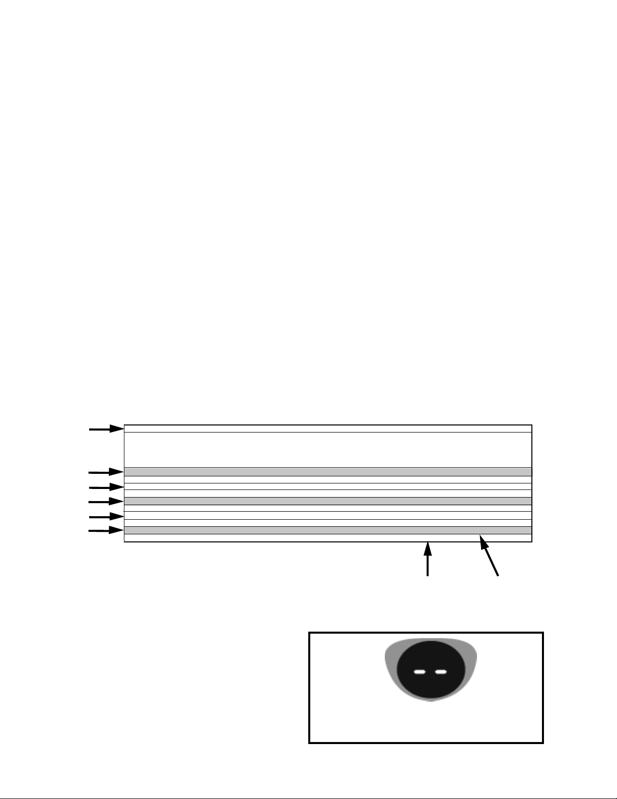
Common Cycle Time Chart Layout
The wash cycles are listed on the left side of the chart. Cycle names such as Anti-Bacterial/BakedOn-Cookware may be designated as Anti-Bacterial on some models and Baked-On-Cookware on
others. Cycle variations are listed directly underneath each cycle name. These variations are dependent on one or more of the following factors:
• What, if any, options were chosen?
• The Soil Sensor detected soil in the water. (NOTE: If the Soil Sensor does not trip during a
particular cycle, the unit defaults to the same variation of the cycle that is applicable for nonsensor models.)
The grey highlighted cycle variations indicate options the customer can select (Notes 1 & 3, pages 31
& 32). The grey highlighted cycle variation Light Soil - ENERGY ST AR is an exception and indicates a
unique default cycle for these models (Note 5, page 33).The unhighlighted cycle variations are based
on input from the soil sensor or are defaults based on specific models (Notes 2 & 4, page 32).
Cycle
Name
Note 1
Note 2
Note 3
Note 4
Note 5
NORMAL NOTES 1A,9,14B,15,16
INTERVAL TIME (min:sec)
HEAVY SOIL WITH P.SCOUR / H.T.SCRUB OPTION [Soil sensed in Interval 42] NOTE 14B 95:00 w/o Th.Holds
NUMERIC DISPLAY CYCLE TIME (spinning “CLOCK” pattern in INTERVALS 45-42 for some models, see NOTE 5)
HEAVY SOIL [Soil sensed in Interval 42] NOTE 1A 95:00 w/o Th.Holds
NUMERIC DISPLAY CYCLE TIME (spinning “CLOCK” pattern in INTERVALS 45-42 for some models, see NOTE 5)
LIGHT SOIL (or Non-Sensor Model) H.T.SCRUB OPTION [No soil sensed in Interval 42] NOTE 14B 87:25 w/o Th.Holds
NUMERIC DISPLAY CYCLE TIME (spinning “CLOCK” pattern in INTERVALS 45-42 for some models, see NOTE 5)
LIGHT SOIL (or Non-Sensor Model) [No soil sensed in Interval 42] NOTE 1A 87:25 w/o Th.Holds
NUMERIC DISPLAY CYCLE TIME (spinning “CLOCK” pattern in INTERVALS 45-42 for some models, see NOTE 5)
LIGHT SOIL (or Non-Sensor Model) [No soil sensed in Interval 42] — E. STAR MODEL NOTE 1A 78:20 w/o Th.Holds
NUMERIC DISPLAY CYCLE TIME (spinning “CLOCK” pattern in INTERVALS 45-42 for some models, see NOTE 5)
Fig. 4-1
Note 1 - Customer Selected Option, Heavy Soils Sensed
Note 2 - No Option Selected, Heavy Soils Sensed
Note 3 - Customer Selected Option, Cycle Adjusted/
Shortened because no soils were sensed. Cycle
variation may be same as Non-Sensor models.
Note 4 - No Option Selected, Cycle Adjusted/Shortened
because no soils were sensed. Cycle variation may be
same as Non-Sensor models.
Notes further
explain
Cycle/Variation
Function
Cycle Duration
NOT
Including
Thermal Holds
Note 5 - No Option Selected, Cycle Adjusted/Shortened
because no soils were sensed. Cycle variation is
unique to Energy Star models.
During Soil Sensing function (Interval 42), the LED
display will show two dashes. Clock countdown will
begin once the cycle variation has been determined.
28
Page 33
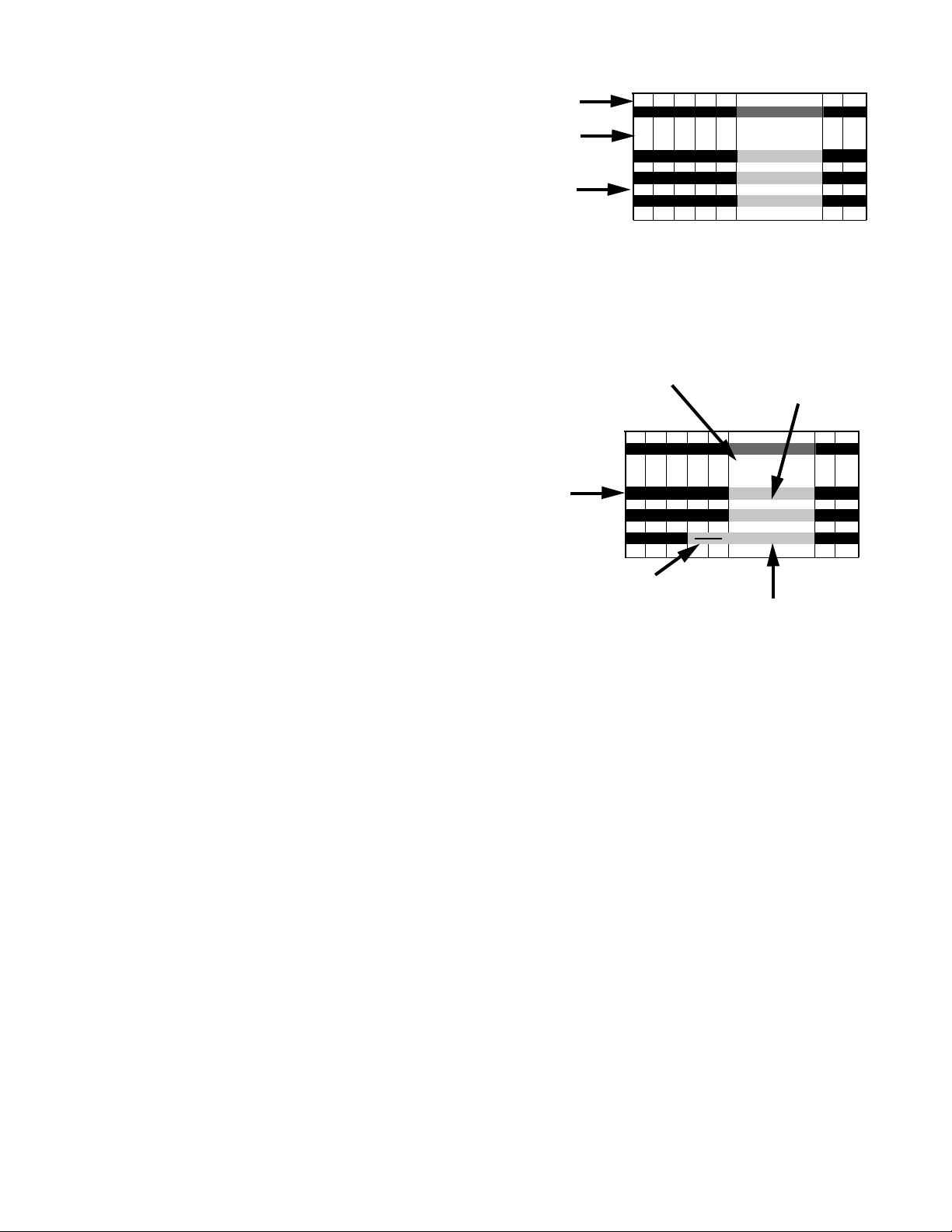
There are 45 intervals in the Common Cycle Time
Chart. Not all intervals have the same time assignments from cycle to cycle. An interval may
be only seconds long or up to 20 minutes in length.
More than one function can take place during an
interval. The display LED will show the time remaining in the cycle. (Fig. 4-2)
Thermal holds may be longer (See Note 2, page
32). Thermal Hold intervals do not show specific
time lengths. The length of these intervals is determined by input from the thermistor. (Fig. 4-3) If
the thermal cap temperature is not reached in a
predetermined length of time, the electronic control will proceed to the next interval.
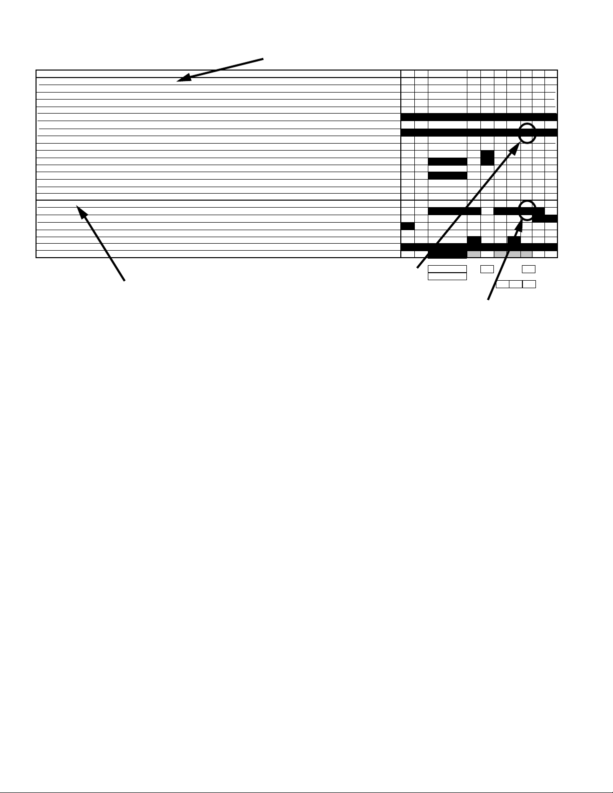
In the same row as the Cycle Name, the shaded
bars indicate all possible intervals that may be
used in that cycle. Black bars indicate intervals
always used. Grey bars with arrows indicate intervals that may be skipped depending on cycle
and options chosen. Shaded bars without arrows
indicate that the heater may or may not be invoked
during thermal holds. (NOTE: During APF and
drain functions the heater is turned off. This is a
UL requirement and is built into the electronic control programming. See Note 2, page 32) Blank
intervals are never used. (Fig. 4-3)
Intervals
Length of
Interval
Time
Remaining
in
Display
Thermal Hold
Intervals do not have
specified time length
Intervals
Always Used
Fig. 4-3
Intervals that
may be skipped
45 44 43 42 41 40 39 38
4:00
2:00
THERMAL HOLD
[135F / 57C]
[135F / 57C]
[135F / 57C]
1:00
0:05
0:05
1:35
[99]
[98]
[98] [98] 94 92 92 91
[99]
[98
[98] [98] 94 92 92 91
[99] [98 [98] [98] 86 84 84 83
Fig. 4-2
Cycle Minutes
Remaining
When Thermal Hold
is Initiated
45 44 43 42 41 40 39 38
0:05
0:05
1:35
[99]
[98]
[98] [98] 94 92 92 91
[99]
[98
[98] [98] 94 92 92 91
[99] [98 [98] [98] 86 84 84 83
THERMAL HOLD
4:00
2:00
[135F / 57C]
[135F / 57C]
[135F / 57C]
>
Thermal Cap
Temperature
1:00
1:00
1:00
Quick Clean/Time Saver Cycle
The Quick Clean/Timer Saver cycle has a unique variation. During the initial water fill, the thermistor
will monitor the incoming water temperature. If it is 135° F (57° C) or above the electronic control will
skip intervals 39 through 36. This shortens the wash/rinse time by eliminating a drain and fill sequence
(See Note 1b and 1c, page 31).
Reading the Common Cycle Time Chart
The following information must be determined before the Common Cycle Time Chart can be used:
• What option, if any, was chosen? (For example: Hi-Temp Scrub)
• Is the Dishwasher a Soil Sensor Model?
• If Soil Sensor Model, did the soils in the water trigger the sensor?
• ON QUICK CLEANUP Cycle: Was the first fill water temperature cool or hot?
With this information in hand, the illumination of status indicators and the operation of functional
components can be verified by looking at the Cycle Progression and Status Indicators (1) and Output
Loads (2) portion of the chart. (Example: In Interval 10 (Final Rinse) the wash motor interval (Output
Loads) is shaded and the Rinse Indicator (Status Indicators) is shaded. This means that the wash
motor should be running and the Rinse LED on the control panel should be lit. (Fig. 4-4)
29
Page 34
(1)
16 15 14 13 12 11 10 9 8
“CYCLE PROGRESSION & STATUS INDICATORS
PROG BAR W1
PROG BAR W2
WASHING (PROG BAR W3)
PROG BAR R1
CIRC (PROG BAR R2) (This LED will be labeled as ‘WASHING’ on models that use it, but it is on during all Wash and Rinse Periods)
RINSING
DRYING
SOAKING NOTE 7
SOAKING/SENSING NOTE 7
ADD-A-DISH
WATER HEATING (THERMAL HOLD INDICATOR) NOTE 6
SANITIZED NOTE 8,15
CLEAN NOTE 8
OUTPUT LOADS
WASH MOTOR (MAIN WINDING)
DRAIN MOTOR NOTE 2
FILL NOTE 2
APF ENABLED INTERVALS -Max # of APF Purges allowed in Interval NOTE 2
DETERGENT / RINSE AID DISPENSER
VENT
HEATER NOTES 4,10,11,16
Fig. 4-4
Rinsing Indicator should be lIt
(2)
17
3
15
94
11 11 11
Wash Motor should be running
Using the Common Cycle Time Chart
To confirm the correct operation of a cycle or properly diagnosis a malfunction, the following information must be determined:
• Does the model have a Soil Sensor?
• What cycle was chosen?
• What Cycle Option was chosen?
• What is the first fill water temperature? (Quick Clean / Time Saver Cycle only)
Proceed with the following steps:
1. Start the selected cycle and program the unit for Rapid Advance service feature. (See page
36).
2. Advance through the intervals to the one that will operate the load or perform the function to be
checked.
3. If the load does not operate, refer to the wiring diagram or applicable strip circuit to determine
what connections and components to check. (See Section Five - TECH TIPS.)
4. Whenever possible, check components for resistance or continuity. On components where
resistance or continuity checks are not reliable, conduct voltage checks.
30
Page 35

COMMON CYCLE TIME CHART NOTES
NOTE 1 – CYCLE MODIFICATIONS BASED ON SENSOR INPUTS
The control monitors food soil and temperature sensors during the first four intervals of the cycle
(intervals 45-42) to determine what sensor based cycle modifications are appropriate. The modifications made to the cycle depend on the cycle and options selected as well as the sensor inputs. Note
the interval skip arrows and thermal hold temperature changes on the time chart for each version of the
cycle.
In addition to being able to modify the cycle itself based on soil sensor input, the APF (
Filtration) wash system allows the control to continuously filter and flush food soil out of the pump
during “APF enabled” intervals scattered throughout each cycle and do it without interrupting the cycle
(see note 2 on APF).
) Anti-Bacterial/Cookware, Pots&Pans/Heavy, Normal, and China Cycles
(a
The control assumes that the worst case cycle (the heavy soil version) is going to be required
until the true soil level is determined. The soil level is determined by counting the number of
pressure switch (soil sensor) trips that occur in the first APF interval of the cycle (
If no trips are detected in interval 42, the control modifies the remainder of the cycle to match
the light soil/non-sensor version of the cycle. If one or more trips are detected in interval 42,
the control continues with the heavy soil version of the cycle.
Note: Energy Star models have a different light soil/non-sensor version of the Normal cycle than other
models (see Model Specifics table to identify Energy Star models).
Note: Models without pressure switches (soil sensors) never get sensor trips and thus always default
to the light/non-sensor version of the cycle and never execute APF purges. (See Model Specifics T able
to identify models without pressure switches).
Note: The Power Scour/High Temp Scrub option can override or alter the soil-based cycle modifications (see Note 14, page 34).
Automatic Purge
interval 42).
(b) Time Saver/Quick CleanUp Cycles
The control does NOT modify the Quick Clean Up/Time Saver cycle based on soil level. Instead, it modifies the cycle based on incoming water temperature detected during the first fill
interval of the cycle (interval 45). The control assumes the worst case cycle (Cool First Fill
version) will be required until the end of interval 42. At the end of interval 42, it modifies the
remainder of the cycle based on the inlet water temperature it actually detected in the first fill.
If the water was more than135°F/57°C it changes to the “Hot First Fill” version of the cycle. If
the water was less than 135°F, it will continue with the “Cool First Fill” version of the cycle. The
“Cool First Fill” version of the cycle basically contains an extra drain and fill prior to the main
wash to increase the initial water temperature for the main wash and reduce the time needed
to heat the water.
Like other cycles, the Quick CleanUp/Time Saver cycle does allow APF purges to occur (in
APF intervals) if pressure switch trips occur but the Quick CleanUp/Time Saver cycle timing
itself is not modified based on pressure switch trips or soil level.
(c) Rinse Only/Quick Rinse Cycles
The control does NOT modify the Rinse Only/Quick Rinse cycle based on sensor inputs. Like
other cycles, it does allow APF purges to occur (in APF intervals) if pressure switch trips occur
but the Rinse Only/Quick Rinse cycle timing itself is not modified based on any sensor inputs.
31
Page 36

NOTE 2 – APF ENABLED INTERVALS
The APF (
food soil out of the pump during “APF enabled” intervals scattered throughout each cycle and do it
without interrupting the cycle. The control monitors the pressure switch (soil sensor) input during each
of the APF enabled intervals in the cycle (see time chart). Whenever a pressure switch trip is detected
in one of these APF intervals, the control executes a 10-second “APF purge” to clear the pump of soil.
These APF purges occur in parallel with the cycle and do not interrupt or affect the timing of other
functions (like washing) that are called for in the interval. Each APF purge consists of 5 seconds of Fill
and Drain followed immediately by 5 seconds of Fill by itself. If an APF purge is executed during a
heated wash interval, the heater must be turned off during the first 5-second Fill and Drain portion of
each purge, but cycle timing is not affected and the heater turns back on mid-way through the purge.
Multiple APF purges can occur within each APF interval of the cycle but are limited by certain frequency
and quantity limits:
• APF purges must be spaced at least 60 seconds apart within any given APF interval (the
• The maximum number of APF purges allowed within a given APF interval is specified on the
Note: Models without pressure switches (soil sensors) never get sensor trips and thus never execute
APF purges. (See Model Specifics Table to identify models without pressure switches).
Automatic Purge Filtration) wash system allows the control to continuously filter and flush
pressure switch will be ignored prior to 60 seconds).
time chart in that interval (the pressure switch will be ignored for the duration of an APF
interval once the maximum APF limit for that interval has been exceeded). In interval 33, the
limit is “1” for 120°F thermal holds and “3” for all other thermal hold setpoint temperatures.
NOTE 3 – WATER HEATING THERMAL HOLD INTERVALS
During water heating thermal holds (intervals 40, 33, & 15), cycle timing is interrupted and the dishwasher continues washing while it heats the water to the setpoint temperatures specified on the time
chart for each version of the cycle. The Water Heating and Sensing indicators are turned on and the
cycle time displayed by models with numeric displays is frozen during thermal hold intervals (see
Notes 5, 6, & 7). The dishwasher will hold in this suspended, water heating mode until the water
reaches the temperature specified for the thermal hold or a maximum default time limit for the thermal
hold (below) expires. At the conclusion of the thermal hold, the control resumes normal operation and
timing and proceeds to the next interval.
The default maximum time limits for all the thermal hold intervals are as follows (in minutes):
Pre-Wash Main Wash Final Rinse (Final Rinse with Sani Rinse)
Anti-Bacterial/Cookware 30 35 50 (50)
Pots & Pans/Heavy 30 35 30 (50)
Normal — 45 40 (60)
China — 45 30 ( — )
(Quick CleanUp/Time Saver and Quick Rinse/Rinse Only cycles have no thermal hold intervals)
NOTE 4 – THERMALLY CAPPED INTERVALS
Interval 34 is a heated wash interval thermally capped at 150°F/66°C. Interval 10 is only heated for the
Quick CleanUp/Time Saver cycle and is thermally capped in that situation at 150°F/66°C. Anytime the
thermal cap temperature is exceeded during one of these intervals, the heater will turn off, but the
dishwasher will continue washing for the duration of the interval.
32
Page 37

NOTE 5 - NUMERIC CYCLE TIME DISPLAY
Some models with numeric cycle time displays show an animated spinning clock pattern during the
first four intervals of the cycle (intervals 45-42) while sensor based cycle modifications (and true time
remaining) are being determined. Other models simply display the worst case cycle time remaining
(in minutes) until the end of interval 42. See the Model Specifics T able to identify models with numeric
displays and which models exhibit the animated clock pattern. At the end of interval 42,
numeric displays will begin displaying a corrected cycle time (in minutes). From here on, the display
clocks down normally, minute by minute, through the rest of the cycle.
all models with
Note: Cycle time does
thermal hold is frozen until the end of the thermal hold (see Notes 3 & 6).
NOTE 6 – WATER HEATING (THERMAL HOLD) STATUS INDICATOR
The Water Heating indicator is turned on during all thermal hold intervals to signal that cycle timing,
display sequencing, and numeric cycle time display countdown operations have been suspended or
frozen while the water is heated to the proper temperature (see Note 3).
NOTE 7 – SOAKING/SENSING & SOAKING STATUS INDICATORS
In general, the
cycles whenever the control is monitoring sensors or still making decisions based on sensor inputs.
Specifically this includes all APF intervals, all thermal hold intervals, and the first four intervals of each
cycle (see Notes 1, 2, and 3).
The Soaking/Sensing indicator also turns on during “soaking” events like the “soaking/pause” intervals
in the Energy Star low soil/non-sensor version of the Normal cycle (see Note 9). A dedicated Soaking
indicator is available for non-numeric models that will likewise turn on during these “soaking” events
but not during “sensing” intervals.
NOTE 8 – ‘END-OF-CYCLE’ STATUS INDICATORS – CLEAN and SANITIZED
Soaking/Sensing indicator is primarily a “sensing” indicator and is turned on during
not include time spent in thermal holds; the time on the display at the start of the
Both end-of-cycle indicators (Clean and Sanitized) turn on at the end of a cycle and turn off upon
pressing any key or opening and closing the door (Note: The indicators stay on as the door is opened
but turn off as soon as the door is closed again).
(a) Clean
Comes on at the end of every cycle except Rinse Only/Quick Rinse.
(b) Sanitized
Comes on at the end of all cycles completed with the Sani Rinse option selected (see Note 15).
If the Sani Rinse option is completed successfully , the indicator is turned on steady at the end
of the cycle. If the Sani Rinse was unsuccessful (see below), the indicator will flash ½ second
on, ½ second off, repeatedly, at the end of the cycle. The Sani Rinse will be deemed unsuccessful (& flash the indicator) if:
(1) The thermal hold in the final rinse (interval 15) fails to reach the required 160°F/71°C before
timing out on its default time limit.
(2) The door is opened and/or power is interrupted between the end of the final rinse thermal hold
(interval 15) and the end of the cycle.
33
Page 38

NOTE 9 - SOAKING PAUSE INTERVAL — ENERGY STAR NORMAL CYCLE ONLY
Intervals 13 and 32 are mid-cycle soaking/pause intervals and are only used in the Energy Star light
soil/non-sensor version of the Normal cycle. The control stops washing and turns all loads off except
the vent in these intervals. The intent is to let the wash water that’s on the dishes soften and loosen the
food soil that’s on the dishes, energy free. The Soaking and Soaking/Sensing indicators are turned on
during these intervals (see Note 7).
NOTE 10 – PULSED DRY — CHINA CYCLE ONLY
The China cycle (on all models) turns the heater off in intervals 1, 3, and 5 of the dry period to create a
gentler “pulsed” dry .
NOTE 11 – HEATER ON — QUICK CLEANUP/TIME SAVER CYCLE ONLY
T o make up for no water heating thermal holds, the heater is turned on in intervals 10-12, 14, and 41-42
of the Quick CleanUp/Time Saver cycle. The heater in interval 10 of the Quick CleanUp/Time Saver
cycle is thermally capped at 150°F/66°C (see Note 4).
NOTE 14 – POWER SCOUR/HIGH TEMP SCRUB OPTION
The Power Scour/High Temp Scrub option is not allowed with China, Quick CleanUp/Time Saver, or
Rinse Only/Quick Rinse cycles. This option does the following:
(a) Anti-Bacterial/Cookware and Pots&Pans/Heavy cycles
• Forces the control to run no less than a 5-fill (Wash-Wash-Rinse-Rinse-Rinse-Dry) version of
the cycle, even if no soil is sensed.
• Raises the pre-wash water heating thermal hold (interval 40) to 135°F/57°C
• Raises the main wash water heating thermal hold (interval 33) to 145°F/63°C (except AntiBacterial/Cookware cycle, which is already 145°F/63°C).
(b) Normal cycles
• Forces the control to run no less than a 4-fill (Wash-Wash-Rinse-Rinse-Dry) version of the
cycle even if no soil is sensed. Note: The standard (non-Energy Star) Normal cycle is already a
minimum of 4-fills (Wash-Wash-Rinse-Rinse-Dry) with light/no soil.
· • Raises the main wash water heating thermal hold (interval 33) to 145°F/63°C.
NOTE 15 – SANI RINSE OPTION
The Sani Rinse option is not allowed on China, Quick CleanUp/Time Saver, and Rinse Only/Quick
Rinse cycles. It is “built in” and treated as an automatic option on the Anti-Bacterial/Cookware cycles.
This option does the following:
• Raises final rinse water heating thermal hold (interval 15) to 160°F/71°C and adds 20 minutes to its default maximum time limit.
· • Turns heater off in the last two intervals of the dry period (intervals 1 and 2).
· • Invokes the Sanitized status indicator at the end of the cycle (see Note 8).
NOTE 16 – AIR DRY/NO HEAT DRY/ENERGY SAVER DRY OPTION
The Air Dry/No Heat Dry option is not allowed on the Rinse Only/Quick Rinse cycle (which has no dry).
This option does the following:
• Turns heater off in the dry period (intervals 1-6).
34
Page 39
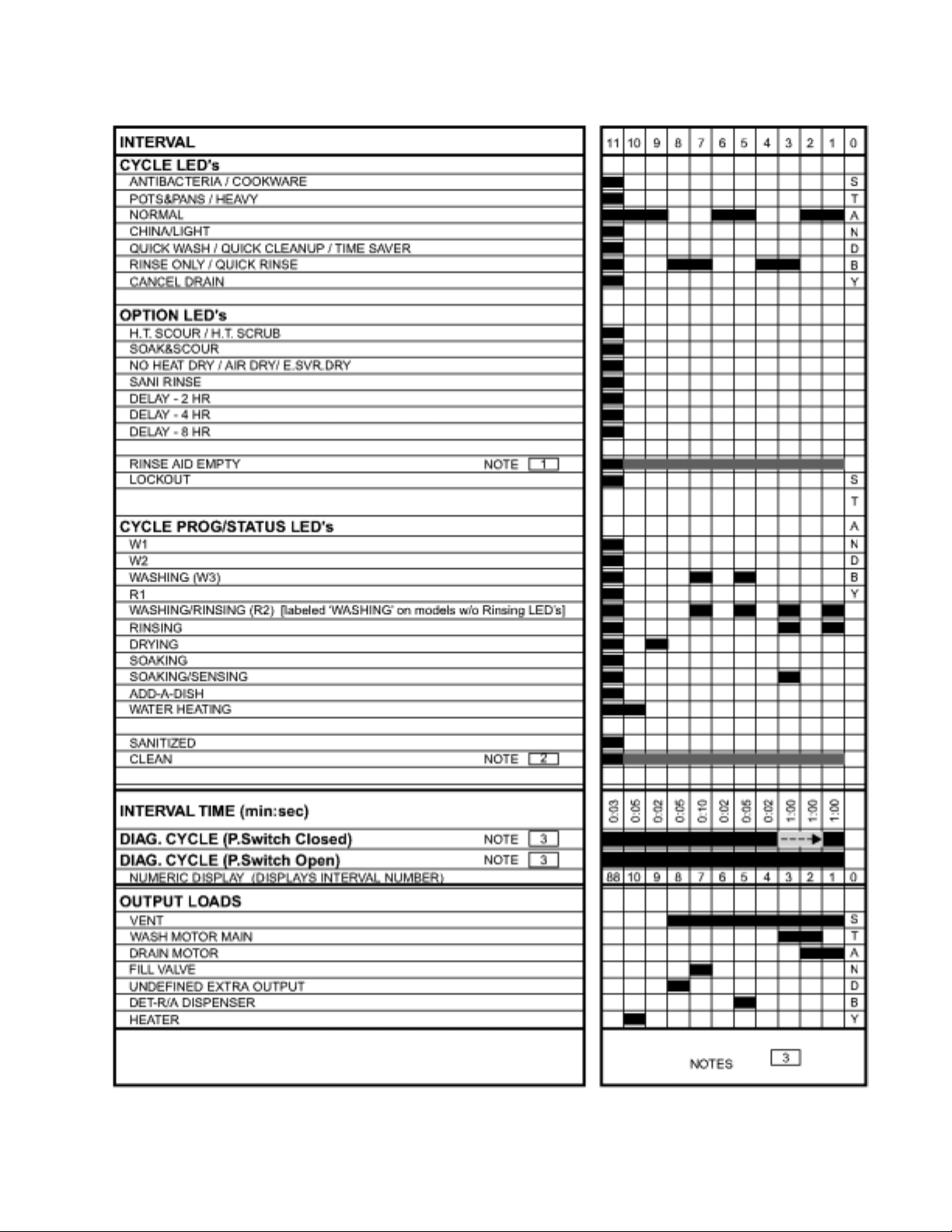
Diagnostic Cycle Time Chart
35
Page 40

RAPID ADV ANCE SERVICE FEA TURE AND DIAGNOSTICS
CYCLES
Pressing the following option keys in the sequence shown will either start the Diagnostics Cycle or turn
on the Rapid Advance feature for stepping through customer selectable cycles:
HIGH TEMP SCRUB, AIR DRY, HIGH TEMP SCRUB, AIR DRY
Or
SANI RINSE, AIR DRY, SANI RINSE, AIR DRY
(Note: HIGH TEMP SCRUB = POWER SCOUR = HIGH TEMP SCOUR)
(Note: AIR DRY = NO HEAT DRY = ENERGY SAVER DRY)
If the above key sequence is entered after starting a cycle, the Rapid Advance feature is turned on,
which allows the operator to manually advance the currently running cycle, interval by interval, by
pressing the Pots&Pans/Heavy or Anti-Bacterial/Cookware or Start key .
If the above key sequence is entered with the dishwasher in Standby, the Diagnostics Cycle is started.
The Diagnostics Cycle can be rapid-advanced, interval by interval, by pressing the Pots & Pans/Heavy
or Anti-Bacterial/Cookware or Start key .
NOTE: The door must be closed before the Diagnostics cycle will run. Likewise, the door must be
closed after each rapid advance selection of the Pots & Pans/Heavy or Anti-Bacterial/Baked On Cookware key for the control to advance to the next interval of the Diagnostics or currently running cycle.
DIAGNOSTICS CYCLE TIME CHART NOTES
(DIAGNOSTICS CYCLE) NOTE 1 – R/A SENSOR ASSY CHECK
To help detect a defective or disconnected Rinse Aid level sensor, the Rinse Aid Empty LED should
light up in Diagnostics if the Rinse Aid dispenser is empty or the circuit is shorted. If the Rinse Aid
dispenser is full, the LED indicator will not light up during the diagnostic test, except in the first increment.
(DIAGNOSTICS CYCLE) NOTE 2 – THERMISTOR OPEN/SHORT DETECTION
The Diagnostics Test cycle will illuminate the ‘CLEAN’ LED throughout the operating portion of the
cycle that follows the initial display test interval whenever it detects a “short circuit” or “open circuit” on
the thermistor input.
NOTE: Warm water must be in the dishwasher when performing this test. The highest thermistor
resistance values the control can detect as its open circuit criteria are close to the normal thermistor
resistances at room temperature. Consequently , this indicator is only reliable for “open circuit” detection if warm water is in the dishwasher.
(DIAGNOSTICS CYCLE) NOTE 3 – STUCK PRESSURE SWITCH DETECTION
The Diagnostics cycle monitors the normally open soil-sensing pressure switch input for a “stuck
closed” condition by aborting wash interval 3 and skipping immediately to drain interval 1 if the control
detects a closed pressure switch.
36
Page 41
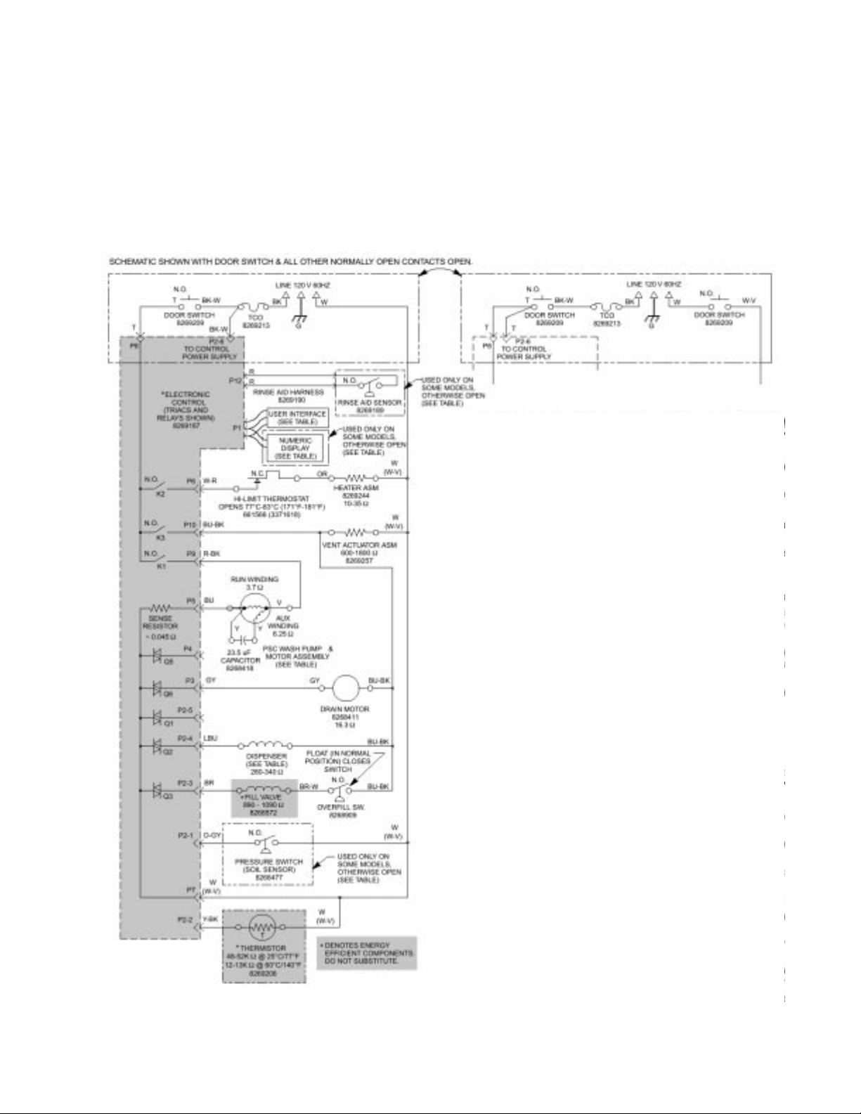
SECTION FIVE
TECH TIPS
WIRING DIAGRAM
Stainless Steel Tub
Wiring Diagram
Plastic Tub
Wiring Diagram
Table References: See next page.
37
Page 42
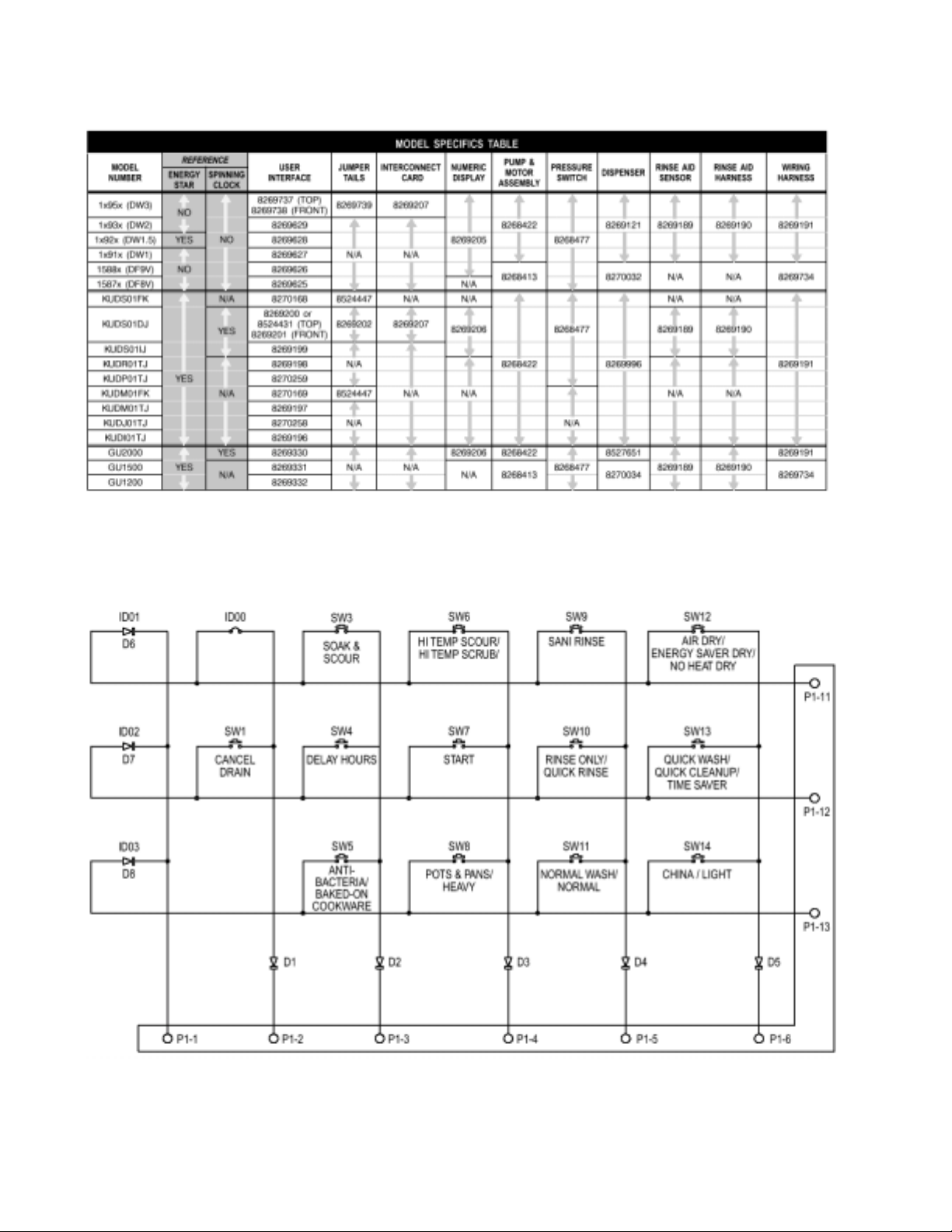
MODEL SPECIFIC SERVICE P ARTS T ABLE
USER INTERF ACE SWITCH MA TRIX
(NOTE: Switches may not appear on all models, IDs vary by model.)
38
Page 43
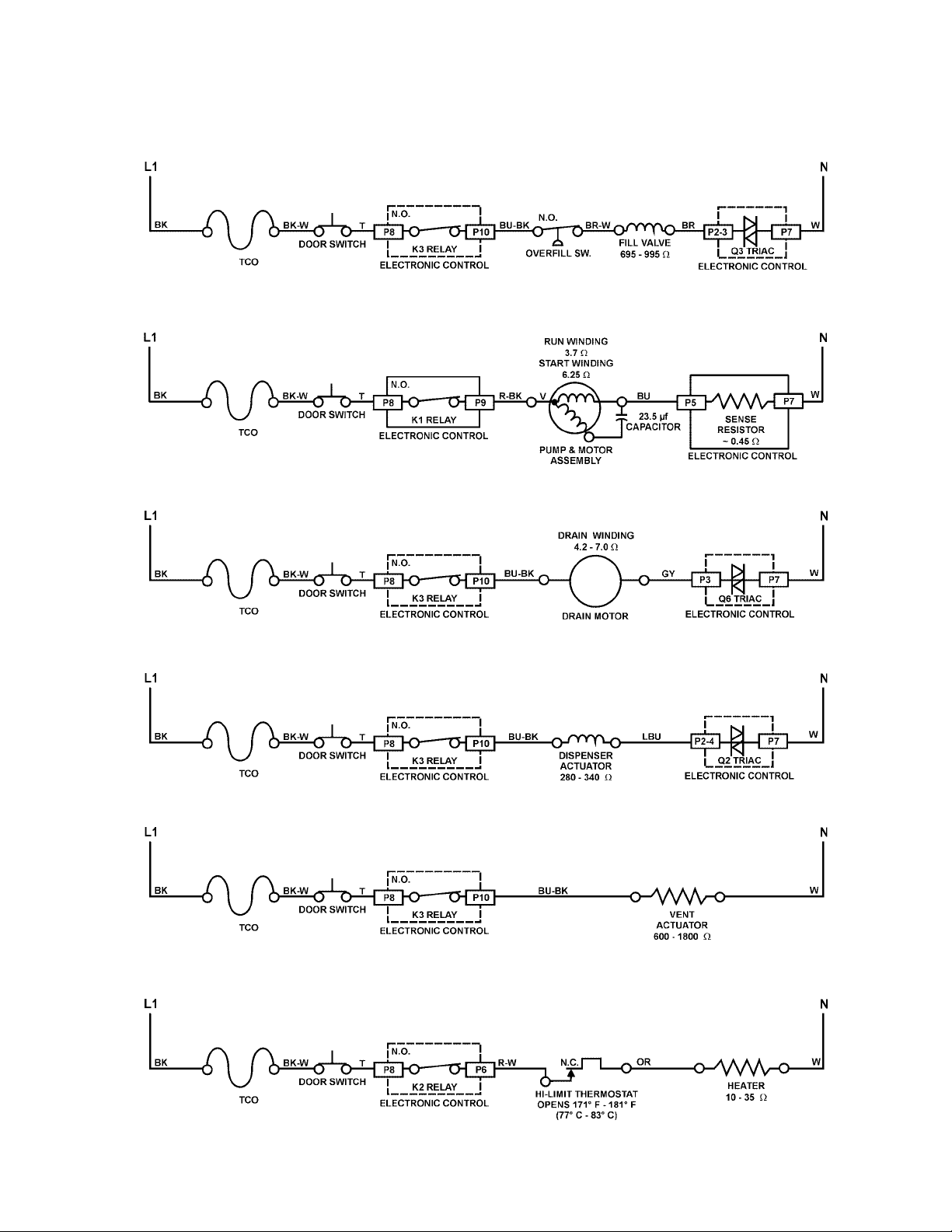
FILL
W ASH/RINSE
DRAIN
STRIP CIRCUITS
DISPENSER
VENT
HEAT DRY
39
Page 44
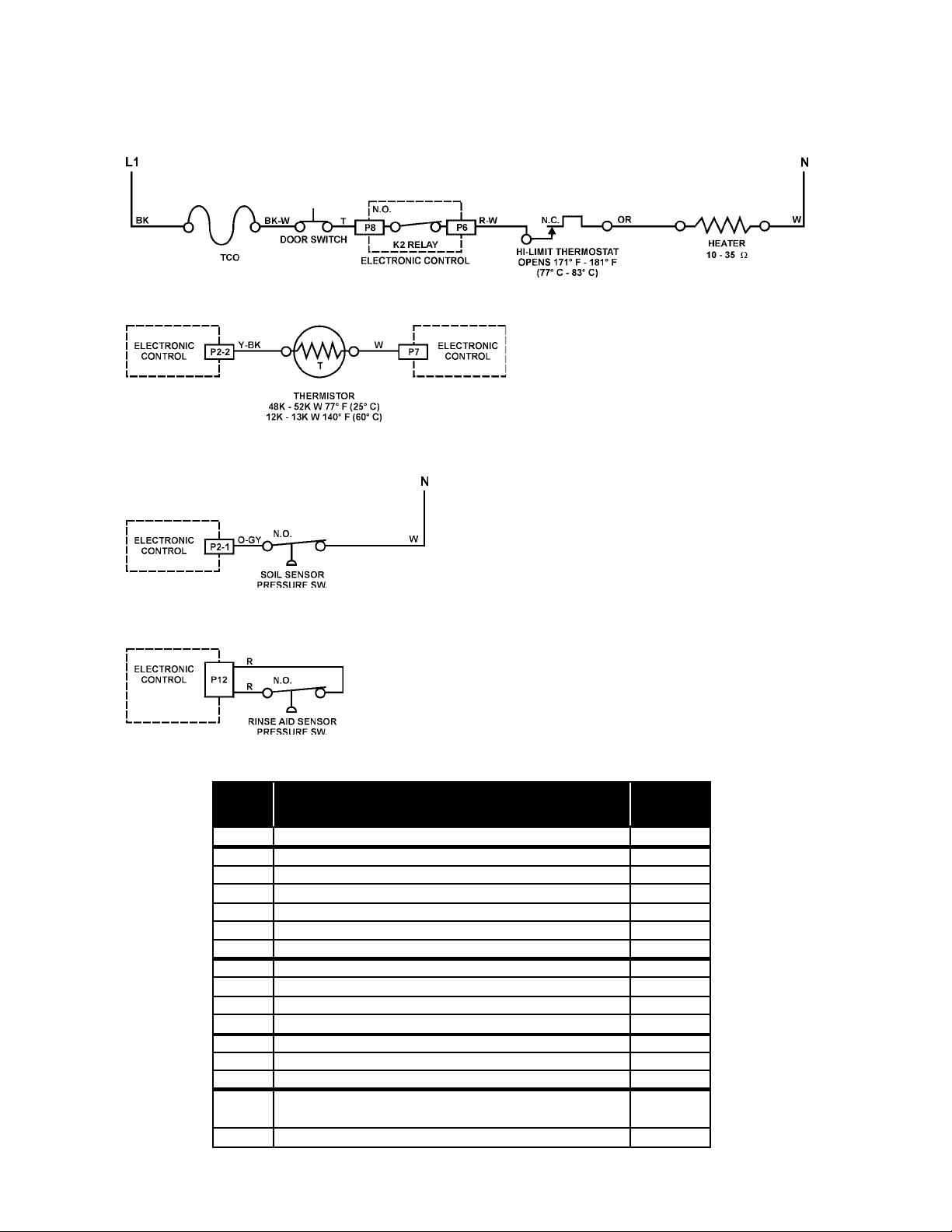
WATER HEATING
Heater Circuit
Thermistor
SOIL SENSING
RINSE AID SENSING
ELECTRONIC CONTROL CONNECTOR PINS
PIN
NO.
P1
P2-1
P2-2
P2-3
P2-4
P2-5
P2-6
P3
P4
P5
P6
P7
P8
P9
P10
P12
DESCRIPTION
RIBBON CABLE TO USER INTERF ACE
PRESSURE SWITCH (SOIL SENSE)
THERMISTOR
FILL V AL VE
DISPENSER
OPEN
TO CONTROL POWER SUPPL Y
DRAIN MOTOR
WASH MOTOR AUX WINDING
WASH MOTOR RUN WINDING
SWITCHED L1 TO HEA TER
AC NEUTRAL
SWITCHED L1 FROM TCO
SWITCHED L1 TO WASH MOTOR COMMON
SWITCHED L1 TO VENT, FILL VAL VE,
DISPENSER & PRESSSURE SWITCH
OPTIONAL RINSE AID
WIRE
COLOR
-
O-GY
Y-BK
BR
LBU
O-BK
T
GY
Y
BU
W-R
W-V
T
R-BK
BU-BK
R
40
Page 45

PRODUCT SPECIFICATIONS
AND
W ARRANTY INFORMATION SOURCES
IN THE UNITED STATES:
FOR PRODUCT SPECIFICATIONS AND WARRANTY INFORMATION CALL:
FOR WHIRLPOOL PRODUCTS: 1-800-253-1301
FOR KITCHENAID PRODUCTS: 1-800-422-1230
FOR ROPER PRODUCTS: 1-800-447-6737
FOR TECHNICAL ASSI ST ANCE WHI LE AT THE CUSTOMER’S HO ME CALL:
THE TECHNICAL ASSISTANCE LINE: 1-800-253-2870
HAVE YOUR STORE NUMBER READY TO IDENTIFY YOU AS AN AUTHORIZED SERVICER
FOR LITERATURE ORDERS:
PHONE #: 1-800-851-4605
_____________________________________________________________________
IN CANADA:
FOR PRODUCT SPECIFICATIONS AND WARRANTY INFORMATION CALL:
1-800-461-5681
FOR TECHNICAL ASSI ST ANCE WHI LE AT THE CUSTOMER’S HO ME CALL:
THE TECHNICAL ASSISTANCE LINE: 1-800-488-4791
HAVE YOUR STORE NUMBER READY TO IDENTIFY YOU AS AN AUTHORIZED SERVICER
41
Page 46

CORPORATION
42
 Loading...