

Whirlpool RF302BXKW0, RF350BXGW1, RF386PXGQ0, RF386PXGW0, RF386PXGZ0 Installation Guide
...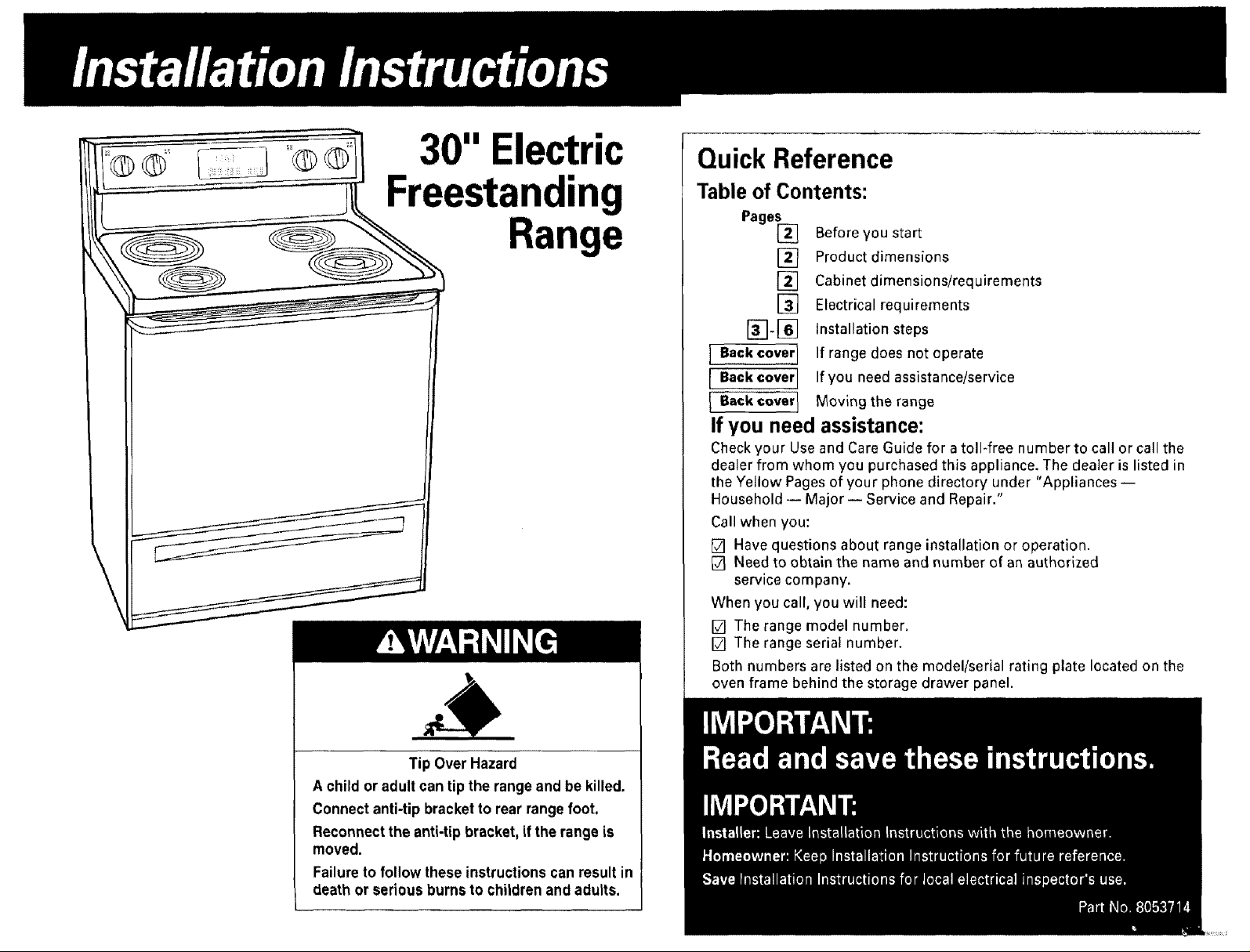
30" Electric
Quick Reference
Freestanding
ange
Table of Contents:
Page_
[ B.k co,_,l
[B._k_o,e,]
I
Before you start
Product dimensions
[]
[]
Cabinet dimensions/requirements
[]
Electrical requirements
Installation steps
If range does not operate
If you need assistance/service
Moving the range
If you need assistance:
Checkyour Use and Care Guide for a toll*free number to callor call the
dealer from whom you purchasedthis appliance. The dealer is listed in
the Yellow Pages of your phone directory under "Appliances--
Household-- Major-- Service and Repair."
Call when you:
[] Have questions about range installation or operation.
[] Need to obtain the name and number of an authorized
service company.
When you call, you will need:
[] The range model number.
[] The range serial number.
Both numbers are listed onthe model/serial rating plate located on the
oven frame behind the storage drawer panel.
Tip Over Hazard
A child or adult can tip the range and be killed.
Connect anti-tip bracketto rear range foot.
Reconnect the anti-tip bracket, if the range is
moved.
Failureto follow these instructions can result in
death or serious burns to children andadults.
Your safety and the safety of others
is very important.
We have provided many important safety
messages in this manual and on your
appliance. Always read and obey all
safety messages.
This is the safety alert symbol. This
symbol alerts you to hazards that can
kill or hurt you and others. All safety
messages will be preceded by the safety
alert symbol and the word "DANGER" or
"WARNING". These words mean:
You will be killed or seriously injured if
you don't follow instructions.
You cannbe killed or seriously injured if
you don't follow instructions,
All safety messages will identify the hazard,
tell you how to reduce the chance of injury,
and tell you what can happen if the
instructions are not followed.
Important: Observe all governing codes and
ordinances.Failure to meet codesand ordinances
could lead to fire or electrical shock.
Proper installation isyour responsibility.A qualified
technicianmust install this range. Make sure you
have everything necessary for correct installation. It
is the installer's responsibility to comply with
installation clearances specified on the model/serial
rating plate. The model/serial rating plate is located
on the oven frame behind the storage drawer panel.
Checklocation where range will be installed.The
range shouldbe located for convenient use in
kitchen.
When installinga range under existing cabinetsand
the installation does not meetthe minimum cabinet
clearances,install a range hood above the cooktop
to avoid burn hazards.
ALL OPENINGS IN THE WALL OR FLOOR WHERE
RANGEIS TO BE INSTALLED MUST BESEALED.
Cabinet opening dimensions that are shown must
be used.Given dimensions are minimum
clearances.
Grounded electrical outlet is required. See
"Electrical requirements," Page 3.
Mobile home installation
The installationof this range must conform with the
Manufactured Home Construction and Safety
Standard, Title 24 CFR,Part 3280 [formerly the
Federal Standard for Mobile Home Construction
and Safety, Title 24, HUD (Part 280)] or, when such
standard is not applicable, the Standard for
Manufactured Home Installations, ANSI
A225.1/NFPA 501A*, or with local codes.
When this range is installed in a mobile home, it
must be secured to the floor during transit. Any
method of securing the range is adequate as long
as it conforms to the standards listed above.
Four-wire power supply cord or cable must be used
in a mobile home installation. The appliance wiring
will need to be revised. See "Four-wire electrical
connection," Page 4.
Copiesofthe standardslisted may be obtainedfrom:
* NationalFireProtectionAssociation
Batten/marchPark
Quincy,Massachusetts02269
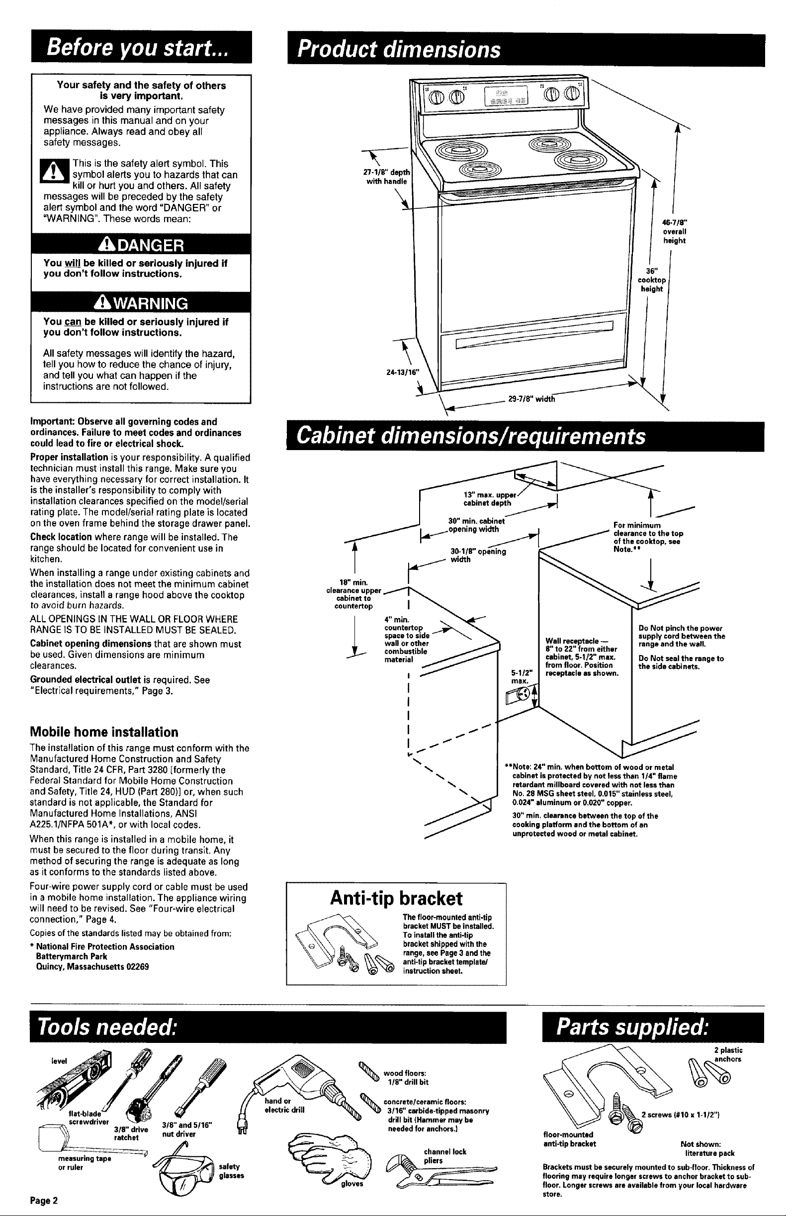
27-1/8" depth
with handle
24-13116"
clearance upper
cabinet to n
countertop I _.,_,_
4" mln. .._
countertop __
I space to side _ " "_ "_
.C wall or other
]_. combustible _j_-,
material
I
I
I
I
I i
Anti-tip bracket
The floor-mounted anti-tip
bracket MUST be installed.
To install the anti-tip
bracket shipped with the
_% ange, see Page3 and the
anti-tip bracket template/
instruction sheet.
_._. 29-7/8" width
Do Not pinch the power
Wall receptacle --
8" to 22" from either
cabinet, 5-1/2" max.
5-1/2" receptacle as shown.
**Note: 24" min, when bottom of wood or metal
cabinet isprotected by not less than 1/4" flame
retardant millboard covered with not less than
No. 28 MSG sheet steel, 0,015" stainless steel,
0.024" aluminum or 0,020" copper.
30" min, clearance between the top of the
cooking platform and the bottom of an
unprotected wood or metal cabinet.
from floor. Position
supply cord between the
range and the wall,
Do Not seal the range to
the side cabinets.
46-7/8"
overall
height
level
flat.blade=
screwdriver
3/8" drive 3/8" and 5116"
measuring tape
or ruler
l retchst
Page 2
nut driver
safety
glasses
"_ 1/8" drill bit
concrete/ceramic floors:
woo,,,,oor.:
3/16" carbide-tipped masonry
drill bit (Hammer may be
needed for anchors.)
channel lock
floor.mounted
2 screws (#10 x 1-112")
anti-tip bracket Not shown:
literature pack
Brackets must be securely mounted to sub-floor. Thickness of
flooring may require longer screws to anchor bracket to sub-
floor. Longer screws are available from your local hardware
store.
Electrical Shock Hazard
Electricallyground range.
Failureto follow this instruction could result in
death, fire or electrical shock.
Ifcodes permit and a separate ground wire isused
it isrecommended that a qualified electrician
determine that the ground path and wire gauge are
in accordancewith local codes.
Do Not ground to a gas pipe.
Checkwith a qualified electrician if you are not
sure range is properly grounded.
Do Not have a fuse in the neutral or ground circuit.
Recommended ground method
It is the personal responsibility and obligation of the
customer to contact a qualified electrician to assure
that the electrical installation is adequate and is in
conformance with the National Electrical Code,
ANSI/NFPA 70 -- latest edition* and all local codes
and ordinances.
Copies of the standards listed above may be
obtained from:
* National Fire Protection Association
Batterymarch Park
Quincy, Massachusetts 02269
Power supply cord is not supplied, but is available
through your local electrical supply house.
Range must beconnected to the proper electrical
voltage and frequency as specified on the
model/serial rating plate. (The model/serial rating
plate is located on the oven frame behind the
storage drawer panel.)
[] CONNECTWITH COPPERWIREONLY.
[] A three-wire or four-wire, single-phase, 120/240-
volt, 60-Hz,AC-only, electrical supply (or three-wire
or four-wire 120/208-volt if specified on the
model/serial rating plate) is required on a separate,
40-ampere circuit, fused on both sides of the line.
[] A time-delay fuse or circuit breaker is
recommended.
[] Local codesmay permit the use of a U.L.-listed,
250-volt, 40-ampere range power supply cord
(pigtail). This cord contains three, No.-10 copper
wires and matches a three-wire receptacle of NEMA
Type 10-50R,shown in Figure 1.Connectors on the
appliance end must be provided at the point the
power supply cord enters the appliance.
[] The range can beconnected directly to the
fused disconnect (or circuit breaker box) through
flexible, armored or non-metallic sheathed, copper
cable (with grounding wire). Allow two to three feet
of slack in the line so that it can be moved if
servicing is ever necessary.
A U,L.-listed conduit connector must be provided at
each end of the power supply cable (at the range
and at the junction box).
Wire sizes (COPPERWIRE ONLY) and connections
must conform with the rating of the range
(40-amperes).
[] The wiring diagram islocated on the back of
the range or on the inside ofthe storage drawer in a
clear plasticbag.
If connecting to a four-wire system:
This range is manufactured with the ground
connected to the cabinet. The ground must be
revised so the green grounding wire of the four-
wire power supply cord is connected to the cabinet.
See "Four-wire electrical connection," section,
Page 4.
When afour-wire receptacle of NEMA Type 14-50R
is used (see Figure 2), a matching U.L.-listed, four-
wire, 250-volt, 40-ampere, range power supply cord
(pigtail) must be used. This cord contains four
copper conductors with ring terminals at the
appliance end, terminating in a NEMA Type 14-50P
plug on the supply end. The fourth (grounding)
conductor must be identified by a green or
green/yellow cover and the neutral conductor by a
white cover. Cord should beType SRD or SRDT
with a U.L.-listed strain relief and be at least four
feet long.
The MINIMUM conductor sizes for the copper
four-wire power cord are:
40-ampere circuit
2, No.-8 conductors
1,No.-10 white neutral
1, No.-8 green grounding
U
3-wire wall
receptacle {lO-50RI
Figure 1
4-wire wall
receptacle (14-50R}
Figure2
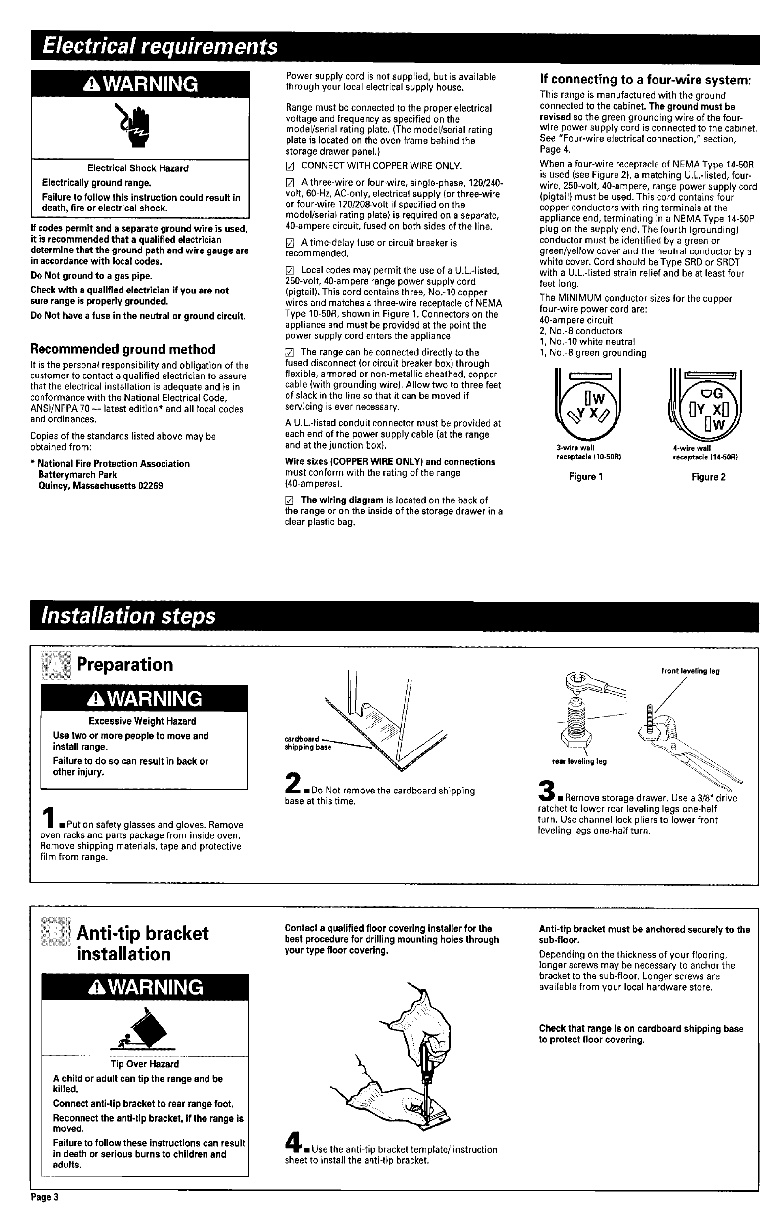
Preparation
ExcessiveWeight Hazard
Usetwo or more people to move and
install range.
Failureto do socan result in back or
other injury.
.. Put on safety glasses and gloves. Remove
oven racks and parts package from inside oven.
Remove shipping materials, tape and protective
film from range.
Anti-tip bracket
installation
cardboard ____
shlppmg base __
iDo Not remove the cardboard shipping
base at this time.
Contact a qualified floor covering installer for the
best procedure for drilling mounting holes through
yourtype floor covering.
front leveling leg
/
rear leveling leg
.. Remove storage drawer. Use a 3/8" drive
ratchet to lower rear leveling legs one-half
turn. Use channel lock pliers to lower front
leveling legs one-half turn.
Anti-tip bracket must be anchored securelyto the
sub-floor.
Depending on the thickness of your flooring,
longer screws may be necessary to anchor the
bracket to the sub-floor. Longer screws are
available from your local hardware store.
Tip Over Hazard
A child or adult can tip the range and be
killed.
Connect anti-tip bracket to rear range foot.
Reconnectthe anti-tip bracket, if the range is
moved.
Failureto follow these instructions can result
in death or serious burnsto children and
adults.
Page3
Check that range is on cardboard shipping base
to protect floor covering.
Use the anti-tip bracket template/instruction
sheet to install the anti-tip bracket.
 Loading...