

Whirlpool WPC45 AM, Gold WPC4524AM41, Gold WPC4530AM41, Gold WPC4536AM41, Gold WPC4542AM41 Installation Instructions Manual
...
INSTALLATION INSTRUCTIONS FOR
a
PACKAGE HEAT PUMP OR PACKAGE COOLING UNIT
Table of Contents
HEAT PUMP/ELECTRIC COOLING SAFETY............................... 1
INSTALLATION REQUIREMENTS ................................................2
Tools and Parts ............................................................................2
Location Requirements................................................................2
Ductwork Requirements ..............................................................4
Electrical Requirements ............................................................... 4
INSTALLATION INSTRUCTIONS ..................................................4
Inspect Shipment ......................................................................... 4
Place Heat Pump or Air Conditioning Unit in Final Location.......5
Connect Condensate Drain ......................................................... 5
Install Ductwork............................................................................5
Filters ............................................................................................ 5
Electric Heat Installation and Adjustment.................................... 6
Make Electrical Connections .......................................................6
Complete Installation ...................................................................7
HEAT PUMP/ELECTRIC COOLING SAFETY
Recognize this symbol as a safety precaution.
Please adhere to the following warnings and cautions when installing, adjusting, altering, servicing or operating this unit.
SEQUENCE OF OPERATION ........................................................7
Start-up Procedure—Cooling Cycle ............................................7
Start-up Procedure—Heat Pump ................................................8
Final System Checks....................................................................8
Explanation and Guidance—Heat Pump.....................................8
Defrost Cycle................................................................................9
System Troubleshooting ............................................................10
Circulating Air Blower.................................................................11
Blower Performance Data ..........................................................12
CHARGE VERIFICATION .............................................................14
SYSTEM MAINTENANCE ............................................................16
TROUBLESHOOTING ..................................................................17
ASSISTANCE OR SERVICE .........................................................20
Accessories ................................................................................20
ATTENTION INSTALLATION PERSONNEL
Prior to installation, thoroughly familiarize yourself with this installation manual. Observe all safety warnings.
During installation or repair, caution is to be observed.
It is your responsibility to install the product safely and to educate the customer on its safe use.
Recognize Safety Symbols, Words and Labels
The following symbols and labels are used throughout this manual to
indicate immediate or potential hazards.It is the owner’s
responsibility to read and comply with all safety information and
instructions accompanying these symbols. Failure to heed safety
information increases the risk of serious personal injury or death,
property damage and/or product damage.
Placeho
for B
Code
Whirlpool Gold® Models
WGPH45**AM, WPC45**AM
WPIO-362
Hazards or unsafe practices could result in property
damage, product damage, severe personal injury or death.
Hazards or unsafe practices may result in property
damage, product damage, personal injury or death.
Hazards or unsafe practices may result in property
or product damage.
Tradewinds Distributing Company, LLC
WARNING
Goodman 1
CAUTION
CAUTION
Goodman 9
14610 Breakers Drive
Jacksonville, FL 32258
WARNING
Installation and repair of this unit should
be performed ONLY by individuals meeting
the requirements of an “Entry Level Technician”
as specified by the Air-Conditioning, Heating and
Refrigeration Institute (AHRI). Attempting to
install or repair this unit without such background may
result in product damage, personal injury or death.
Goodman 7
WARNING
HIGH VOLTAGE!
Goodman 6
Disconnect ALL power before servicing.
Multiple power sources may be present.
Failure to do so may cause property damage,
personal injury or death.
WARNING
Do not connect to or use any device that is not designcertified for use with this unit. Serious property damage,
personal injury, reduced unit performance and/or hazardous
conditions may result from the use of such non-approved
devices.
Goodman 36
WARNING
Connecting unit ductwork to unauthorized heat producing
devices such as a fireplace insert, stove, etc., may result
in property damage, fire, carbon monoxide poisoning,
explosion, personal injury or death.
Goodman 98
WARNING
This product contains or produces a chemical or
chemicals which may cause serious illness or death and
which are known to the State of California to cause
cancer, birth defects or other reproductive harm.
Goodman 45
WARNING
This unit must not be used as a “construction heater”
during the finishing phases of construction on a new
structure. This type of use may result in premature failure
of the unit due to extremely low return air temperatures
and exposure to corrosive or very dirty atmospheres.
Goodman 79
WARNING
Goodman 37
To prevent the risk of property damage, personal injury, or
death, do not store combustible materials or use gasoline
or other flammable liquids or vapors in the vicinity of this
unit.
IMPORTANT: The United States Environmental Protection
Agency (EPA) has issued various regulations regarding the
introduction and disposal of refrigerants in this unit. Failure to
follow these regulations may harm the environment and can lead
to the imposition of substantial fines. These regulations may vary
by jurisdiction. A certified technician must perform the installation
and service of this product. Should questions arise, contact your
local EPA office.
This product is designed and manufactured to permit installation
in accordance with national codes. It is the installer’s
responsibility to install this unit in accordance with national codes
and/or prevailing local codes and regulations.
INSTALLATION REQUIREMENTS
These instructions are intended as a general guide only for use by
qualified persons and do not supersede any national or local
codes in any way. Compliance with all local, state, or national
codes pertaining to this type of equipment should be determined
prior to installation.
Read this entire instruction manual, as well as the instructions
supplied in separate equipment, before starting the installation.
The installation of the heat pump or air conditioning unit, wiring,
warm air ducts, venting, etc., must conform to the requirements
of the National Fire Protection Association; the National Electrical
Code, ANSI/NFPA No. 70 (latest edition) in the United States, and
any state laws, local ordinances (including plumbing or
wastewater codes). Local authorities having jurisdiction should
be consulted before installation is made. Such applicable
regulations or requirements take precedence over the general
instructions in this manual.
Tool s and Parts
Gather the required tools before starting installation. Read and
follow the instructions provided with any tools listed here.
2
Tools needed
■ ⁵⁄₁₆" nut driver
■ Screwdriver
Parts needed
Check local codes and existing electrical supply. Read “Electrical
Requirements” and “Ductwork Requirements” before purchasing
parts.
■ Tap e mea s ure
Location Requirements
Consider the effect of the outdoor fan noise on conditioned
space and any adjacent occupied space. It is recommended that
the unit be placed so that the condenser air discharge does not
blow toward windows less than 25 ft (7.6 m) away.
Heat pumps require special location consideration in areas of
heavy snow accumulation and/or areas with prolonged
continuous subfreezing temperatures. Heat pump unit bases
have holes under the outdoor coil to permit drainage of defrost
water accumulation. The unit must be situated to allow free
unobstructed drainage of the defrost water and ice. A minimum
2" (5.1 cm) clearance under the outdoor coil is required in milder
climates.
Ground Level Preinstallation Details
The unit should be set on a solid, level foundation, preferably a
concrete slab at least 4" (10.2 cm) thick. The slab should be
above ground level and surrounded by a graveled area for good
drainage. Any slab used as a unit’s foundation should not adjoin
the building, since it is possible that sound and vibration may be
transmitted to the structure.
Rooftop Preinstallation Details
Check that the roof is weathertight and allows proper drainage of
condensation. Use steel or treated wood beams as unit support
for load distribution.
NOTE: To ensure proper condensate drainage, the unit must be
installed in a level position.
■ To avoid possible property damage or personal injury, the
roof must have sufficient structural strength to carry the
weight of the unit(s) and snow or water loads as required by
local codes. Consult a structural engineer to determine the
weight capabilities of the roof.
■ The unit may be installed directly on wood floors or on Class
A, Class B, or Class C roof covering material.
■ To avoid possible personal injury, a safe, flat surface for
service personnel should be provided.
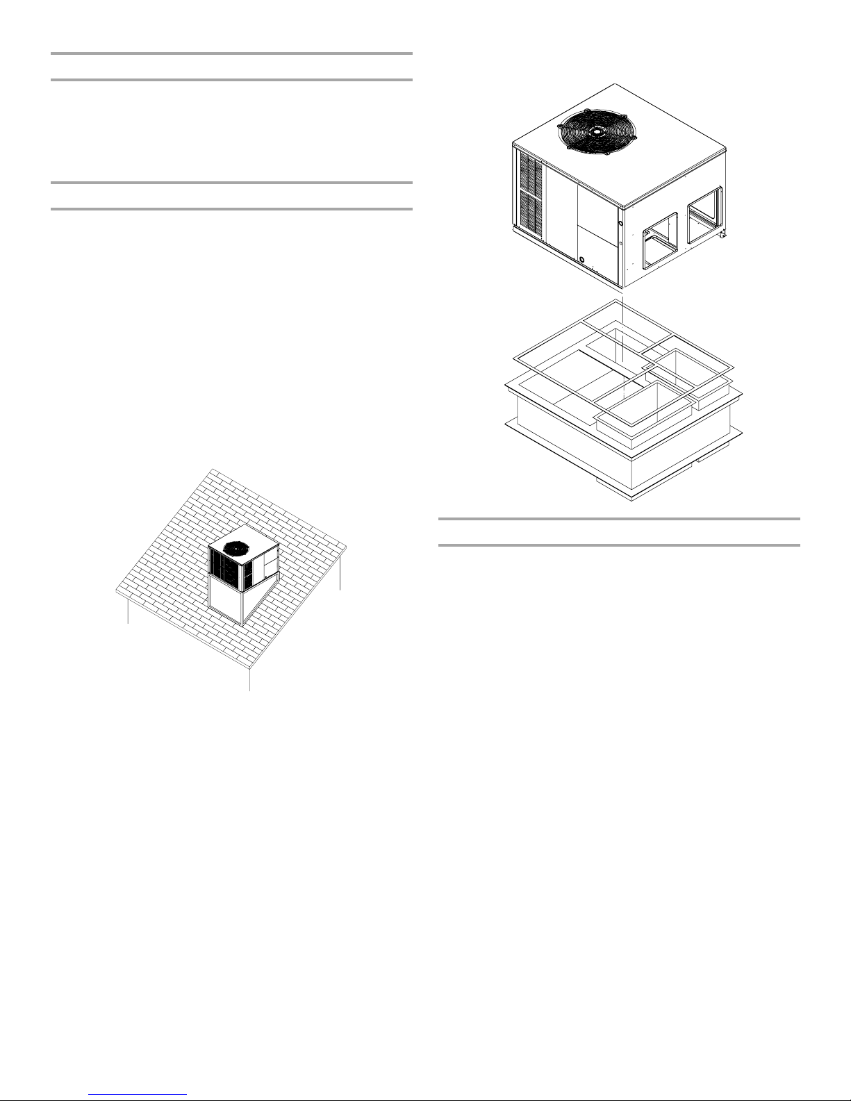
Rooftop Installation
■ The ductwork must be placed into the roof curb before
mounting the package unit.
Roof Curb G 2009 ENV3
Roof Curb Installations Only
NOTES:
■ Sufficient structural support must be determined prior to
locating and mounting the curb and package unit.
■ Curb insulation, cant strips, flashing and general roofing
material are furnished by the contractor.
■ Curbing must be installed in compliance with the National
Roofing Contractors Association Manual.
■ Construct ductwork using current industry guidelines.
Minimum Clearances
The unit is designed to be located outside the building with an
unobstructed condenser air inlet and discharge. Additionally, the
unit must be situated to permit access for service and
installation.
Condenser air enters from 3 sides. Air discharges upward from
the top of the unit. Refrigerant gauge connections are made on
the right-hand side of the unit as you face the compressor
compartment.
Electrical connections can be made on the right-hand side of the
unit. The best and most common application is for the unit to be
located 10" (25.4 cm) from the wall (4" [10.2 cm] minimum) with
the connection side facing the wall. This close-to-the-wall
application minimizes exposed wiring. Close-to-the-wall
application assures free, unobstructed air to the other 2 sides. In
more confined application spaces, such as corners, provide a
minimum 10" (25.4 cm) clearance on all air inlet sides.
Allow 18" (45.7 cm) minimum for service access to the
compressor compartment and controls. The top of the unit
should be completely unobstructed.
If the unit is to be located under an overhang, there should be a
minimum of 36" (91.4 cm) clearance and provisions made to
deflect the warm discharge air out from under the overhang.
3

Minimum Clearances
36"
(91.4 cm)
36"
(91.4 cm)
B
10"
(25.4 cm)
A
C
36"
(91.4 cm)
Down Discharge Applications
Cut insulation around bottom openings and remove panels from
the bottom of the unit, saving the screws holding the panels in
place.
NOTE: Single phase models require installation of horizontal duct
kit #20464501PDGK (medium chassis) and #20464502PDGK
(large chassis).
Panel Removal
A. Wall
B. Unit
C. Curb
Ductwork Requirements
■ Install all conditioned air plenums, ducts and air filters in
accordance with NFPA 90B Standard for the Installation of
Warm Air Heating and Air-Conditioning Systems (latest
edition).
■ The heat pump or air conditioning unit is provided with
flanges for the connection of the plenum and ducts.
■ All air filters must be listed as Class 2 air filters.
■ All ductwork must be made of materials and insulated to
meet local, state and national codes. Ductwork installed
outdoors must be sealed, weatherproof and sheltered against
physical damage. Caulking, flashing or other means of
adequately providing a permanent weather seal should be
used where duct penetrates a building or structure opening.
Airflow Conversion
Units can easily be converted from horizontal to downflow airflow
delivery. In downflow or high static installations, the installer
should measure the total external static and review the blower
performance charts before performing the installation. In some
installations it will be necessary to change the blower speed to
provide proper airflow.
Horizontal Airflow
Single phase models are shipped without horizontal duct covers.
If needed, these kits may be ordered through your local supplier.
B
A
A. Supply air panel
B. Return air panel
Electrical Requirements
WARNING
HIGH VOLTAGE!
Disconnect ALL power before servicing.
Multiple power sources may be present.
Failure to do so may cause property damage,
personal injury or death.
NOTE: All outdoor wiring must be suitable for outdoor use. Use
copper conductors only.
■ All field wiring must be done in accordance with National
Electrical Code requirements, applicable requirements of UL,
or local codes, where applicable.
■ Electrical wiring, disconnect means and over-current
protection are to be supplied by the installer. Refer to the
rating plate for the maximum over-current protection,
minimum service ampacity, and operating voltage. See the
wiring connection diagrams in “Troubleshooting.”
■
This heat pump or air conditioning unit must be electrically
grounded in accordance with National Electric Code (ANSI/
NFPA 70) requirements, applicable requirements of UL, or local
codes, where applicable.
Goodman 6
INSTALLATION INSTRUCTIONS
Inspect Shipment
This heat pump or air conditioning unit is shipped in one
package, completely assembled and wired. The indoor
thermostat and accessories are shipped in a separate carton
when ordered.
■ Check the heat pump or air conditioning unit rating plate to
confirm specifications are as ordered.
■ Upon receipt of heat pump or air conditioning unit, inspect it
for possible shipping damage.
4
Be sure to examine the heat pump or air conditioning unit
inside the carton if the carton is damaged.
■ If damage is found, it should be noted on the carrier’s freight
bill. Damage claims should be filed with the carrier
immediately. Claims of shortages should be filed with the
seller within 5 days.
NOTE: If any damages are discovered and reported to the carrier,
do not install the heat pump or air conditioning unit, since your
claim may be denied.
Place Heat Pump or Air Conditioning Unit in
Final Location
A
F
WARNING
To prevent property damage, the unit should remain in
an upright position during all rigging and moving
operations. To facilitate lifting and moving when a crane
is used, place the unit in an adequate cable sling.
Goodman 109
WARNING
To prevent property damage, personal injury or death,
ensure the roof has sufficient structural strength to carry
the weight of the unit(s), roof curb, snow loads and water
loads as required by local codes. Consult a structural
engineer to determine the weight capabilities of the roof.
Goodman 110
CAUTION
To avoid possible personal injury, a safe, flat surface for
service personnel should be provided.
IMPORTANT: If you are using a bottom discharge with the roof
curb, the ductwork should be attached to the curb prior to the
installation of the unit.
Lower the unit carefully onto the roof mounting curb. While you
are rigging the unit, the center of gravity will cause the condenser
end of the unit to be lower than the supply air end.
Rigging
The condensate drain connection of the evaporator is a half
coupling of ³⁄₄" N.P.T. A ³⁄₄" drain line with trap must be installed
on all applications to avoid accumulation of condensate.
Condensate Drain Connection
■ Install the condensate drain trap as shown. Use a ³⁄₄" (1.9 cm)
NPT drain connection size or larger.
■ An external trap must be installed for proper condensate
drainage.
■ Unit must be level or slightly inclined toward drain.
Goodman 111
Placeholder for Rigging art
Connect Condensate Drain
E
D
A. Drain connection
B. 2" (5.1 cm) minimum
C. 3" (7.6 cm) minimum
B
C
D. Positive liquid seal (required)
E. Flexible tubing, hose or pipe
F. U n it
Install Ductwork
IMPORTANT:
■ Install ductwork in accordance with NFPA 90B and any local
codes.
■ When the unit is installed so that the supply ducts carry air
circulated by the unit to areas outside the space containing
the unit, the return air shall be handled by a duct or ducts
sealed to the unit casing and terminated outsides the space
containing the unit.
■ If there is no complete return air duct system, the return air
connection must be sealed to the unit casing and run full size
to a location outside the utility room or space housing the unit
to avoid a negative pressure on the venting system.
Filters
Filters are not provided with unit, and must be supplied and
installed in the return duct system by the installer. A field installed
filter grille is recommended for easy and convenient access to
the filters for periodic inspection and cleaning. Filters must have
adequate face area for the rated quantity of the unit. See the Air
Delivery Table for the recommended filter size.
Air Delivery Table
Nominal Filter Area
Minimum Filter Size
Nominal Size—in. (cm) Nominal Area—sq ft (cm
10 x 20 (25.4 x 50.8) 1.4 (1,301)
14 x 20 (35.6 x 50.8) 1.9 (1,765)
14 x 25 (35.6 x 63.5) 2.4 (2,230)
15 x 20 (38.1 x 50.8) 2.1 (1,951)
16 x 20 (40.6 x 50.8) 2.2 (2,044)
16 x 25 (40.6 x 63.5) 2.8 (2,601)
20 x 20 (50.8 x 50.8) 2.8 (2,601)
20 x 25 (50.8 x 63.5) 3.5 (3,252)
25 x 25 (63.5 x 63.5) 4.3 (3,995)
2
sq ft (cm
)
7
(6,503)
6
(5,574)
5
(4,645)
4
(3,716)
3
(2,787)
2
(1,858)
Disposable Filter
Permanent Filter
500 1,000 1,500 2,000 2,500 3,000 3,500
Airflow - SCFM
2
)
5

Electric Heat Installation and Adjustment
Make Electrical Connections
WARNING
Goodman 6
Disconnect ALL power before servicing.
Multiple power sources may be present.
Failure to do so may cause property damage,
personal injury or death.
This series of electric cooling and heat pump package equipment
is designed to accept a field installed electric heat kit. The unit is
equipped to easily install the HKR Series Electric Heat Kit. Full
installation instructions are included in this kit. Please use this
document for guidance in field equipping the package unit with
electric heat.
Choose the heat kit that fits the application for the specific
installation. Permanently mark the unit’s nameplate with the
model being installed. High and low voltage connections are
detailed in the heat kit instructions.
Indoor blower motor speed tap selection may need to be
modified to accommodate normal continuous operation to
prevent a nuisance trip. See the following charts.
WPC45(24-48) Models
Unit Model Number 5 8 10 15 20
WPC4524AM41 3 3 3 x x
WPC4530AM41 3333x
WPC4536AM41 3333x
WPC4542AM41 3333x
WPC4548AM41 33333
All models are factory-shipped at T3 speed.
WGPH45(24-60) Models
Unit Model Number 5 8 10 15 20
WGPH4524AM41 x x x
WGPH4530AM41 x x x x
WGPH4536AM41 x x x x
WGPH4543AM41 x x x x
WGPH4549AM41 x x x x x
WGPH4560AM41 x x x x x
HIGH VOLTAGE!
Electric Heat KW
Electric Heat KW
Wiring
WARNING
Goodman 6
Disconnect ALL power before servicing.
Multiple power sources may be present.
Failure to do so may cause property damage,
personal injury or death.
All wiring should be made in accordance with the National
Electrical Code (N.E.C). The local power company should be
consulted to determine the availability of sufficient power to
operate the unit. The voltage, frequency and phase at the power
supply should be checked to make sure it corresponds to the
unit’s rated voltage requirement.
Install a branch circuit fused disconnect near the unit, in
accordance with the N.E.C. or local codes. Wire sizes and overcurrent protection should be determined from the unit nameplate
ampacity and in accordance with Branch Circuit Ampacity chart
or the N.E.C. Under no circumstances should wiring be sized
smaller than is recommended by either of these 2 sources.
Branch Circuit
Ampacity
Supply Wire
Length—ft (m) 15 20 25 30 35 40 45 50
200 (61) 64443322
150 (45.7) 86644433
100 (30.5) 108866644
50 (15.2) 14 12 10 10 8 8 6 6
Fuses smaller than that recommended on the wiring diagrams
could result in unnecessary fuse failure or service calls. The use
of protective devices of larger size than indicated could result in
extensive damage to the equipment. The manufacturer bears no
responsibility for damage caused to equipment as result of the
use of larger than is recommended size protective devices.
All units have undergone a run test prior to packaging for
shipment. This equipment has been started at minimum rated
voltage and checked for satisfactory operation. Do not attempt to
operate this unit if the voltage is not within the minimum and
maximum voltages shown on nameplate.
All exterior wiring must be within approved weatherproof conduit.
The unit must be permanently grounded in accordance with local
codes, or in absence of local codes, with N.E.C. ANSI/ NFPA No.
70-1984 or latest edition by using ground lug in the control box.
Fuses or HACR type circuit breakers may be used where codes
permit.
HIGH VOLTAGE!
6
High Voltage Wiring
Single Phase—Connect the 2 leads to terminals L1 and L2 in the
electrical control section, using wire sizes specified in the wiring
table.
 Loading...