

Whirlpool SCS3017RB00, SCS3617RS01, SCS3617RS00, SCS3617RQ01, SCS3617RQ00 Installation Guide
...
INSTALLATIONINSTRUCTIONS
30" (76 CM) AND 36" (91.4 CM)
GAS BUILT-INCOOKTOP
INSTRUCTIONS D.'INSTALLATION
TABLEDECUISSON A GAZ EN CASTREE
DE30" (76 CM) OU DE 36" (91,4 CM)
Table of Contents / Table des mati@res
COOKTOP SAFETY ......................................... 1
INSTALLATION REQUIREMENTS .................. 2
Tools and Parts ............................................. 2
Location Requirements ................................. 2
Electrical Requirements ................................ 4
Gas Supply Requirements ............................ 4
INSTALLATION INSTRUCTIONS .................... 5
Prepare Cooktop for Installation ................... 5
Install Cooktop .............................................. 6
Make Gas Connection .................................. 7
Attach Cooktop to Countertop ..................... 8
Complete Installation .................................... 8
WIRING DIAGRAMS ........................................ 9
S¢CURIT¢ DE LA TABLE DE CUISSON .......10
EXIGENCES D'INSTALLATION ..................... 11
Outillage et pieces ....................................... 11
Exigences d'emplacement .......................... 11
Specifications _lectriques ............................ t3
Specifications de I'alimentation en gaz ....... 13
INSTRUCTIONS D'INSTALLATION ............... 15
Pr6paration de la table de cuisson
pour I'installation .......................................... 15
Installation de la table de cuisson ............... 15
Raccordement au gaz .................................. 16
Fixation de la table de cuisson au plan
de travail ....................................................... 17
Achever I'installation .................................... 17
SCHEMAS DE CABLAGE .............................. 19
COOKTOP SAFETY
Your safety and the safety of others are very important.
We have provided many important safety messages in this manual and on your appliance. Always read and obey all safety
messages.
This is the safety alert symbol.
This symbol alerts you to potential hazards that can kill or hurt you and others.
All safety messages will follow the safety alert symbol and either the word "DANGER" or "WARNING."
These words mean:
You can be killed or seriously injured if you don't immediately
follow instructions.
You can be killed or seriously injured if you don't follow
instructions.
All safety messages will tell you what the potential hazard is, tell you how to reduce the chance of injury, and tell you what can
happen if the instructions are not followed.
_MPORTANT:
_nstaHer: Leave installation instructions with the homeowner.
Homeowner: Keep installation instructions for future reference.
Save installation instructions for local electrical inspector's use.
_MPORTANT :
_nstaHateur : Remettre les instructions d'installation au propri6taire.
Propri6taire : Conserver les instructions d'installation pour r6ference ult6rieure.
Conserver les instructions d'instailation pour consultation par I'inspecteur local des installations electriques.
8286304
I WARNING: For your safety, the information in this manual must be followed to minimize
the risk of fire or explosion, or to prevent property damage, personal injury, or death.
- Do not store or use gasoline or other flammable vapors and liquids in the vicinity of this
or any other appliance.
- WHAT TO DO IF YOU SMELL GAS:
• Do not try to light any appliance.
• Do not touch any electrical switch; do not use any phone in your building.
• Clear the room, building, or area of all occupants.
• Immediately call your gas supplier from a neighbor's phone. Follow the gas supplier's
instructions.
• If you cannot reach your gas supplier, call the fire department.
- Installation and service must be performed by a qualified installer, service agency, or
the gas supplier.
In the State of Massachusetts, the following installation instructions apply:
= Installations and repairs must be performed by a qualified or licensed contractor, plumber, or gasfitter qualified or licensed by
the State of Massachusetts.
= If using a ball valve, it shall be a T-handle type.
= A flexible gas connector, when used, must not exceed 3 feet.
INSTALLATIONREQUIREMENTS
Gather the required tools and parts before starting installation.
Tools needed
• Tape measure
• Flat-blade screwdriver
• 1%6"combination wrench
• Pipe wrench
• Channel lock pliers
Parts supplied
• Gas pressure regulator
• Burner grates
• Burner caps
• Clamp brackets (2)
• 21/2''(6.4 cm) clamping screws (2)
Parts needed
Check local codes and consult gas supplier. Check existing gas
supply and electrical supply. See "Electrical Requirements" and
"Gas Supply Requirements" sections.
• Marker or pencil
• Pipe-joint compound
resistant to LP gas
• Noncorrosive leak-detection
solution
IMPORTANT: Observe all governing codes and ordinances. Do
not obstruct flow of combustion and ventilation air.
• It is the installer's responsibility to comply with installation
clearances specified on the model/serial rating plate. The
model/serial rating plate is located on the underside of the
ceoktep burner box.
• To eliminate the risk of burns or fire by reaching over heated
surface units, cabinet storage space located above the
surface units should be avoided. If cabinet storage is to be
provided, the risk can be reduced by installing a range hood
that projects horizontally a minimum of 5" (12.7 cm) beyond
the bottom of the cabinets.
• The cooktop should be installed in a location away from
strong draft areas, such as windows, doors and strong
heating vents or fans.
• All openings in the wall or floor where cooktop is to be
installed must be sealed.
• Cabinet opening dimensions that are shown must be used.
Given dimensions are minimum clearances.
• Grounded electrical supply is required. See "Electrical
Requirements" section. Proper gas supply connection must
be available. See "Gas Supply Requirements" section.
• The cooktop is designed to hang from the countertop by its
side or rear flanges.
• Thegasandelectricsupplyshouldbelocatedasshownin
"InstallationClearances"sectionsothattheyareaccessible
withoutrequiringremovalofthecooktop.
• Providecutoutinrightrearcornerofcutoutenclosureas
showntoprovideclearanceforgasinlet,powersupplycord,
andtoallowtheratinglabeltobevisible.
IMPORTANT:Toavoiddamage,checkwithyourbuilderor
cabinetsuppliertomakesurethatthematerialsusedwillnot
discolor,delaminateorsustainotherdamage.
Mobile Home - Additional Installation Requirements
The installation of this cooktop must conform to the Manufactured
Home Construction and Safety Standard, Title 24 CFR, Part 3280
(formerly the Federal Standard for Mobile Home Construction and
Safety, Title 24, HUD Part 280). When such standard is not
applicable, use the Standard for Manufactured Home
Installations, ANSI A225.1/NFPA 501A or with local codes.
In Canada, the installation of this cooktop must conform with the
current standards CAN/CSA-A240-1atest edition, or with local
codes.
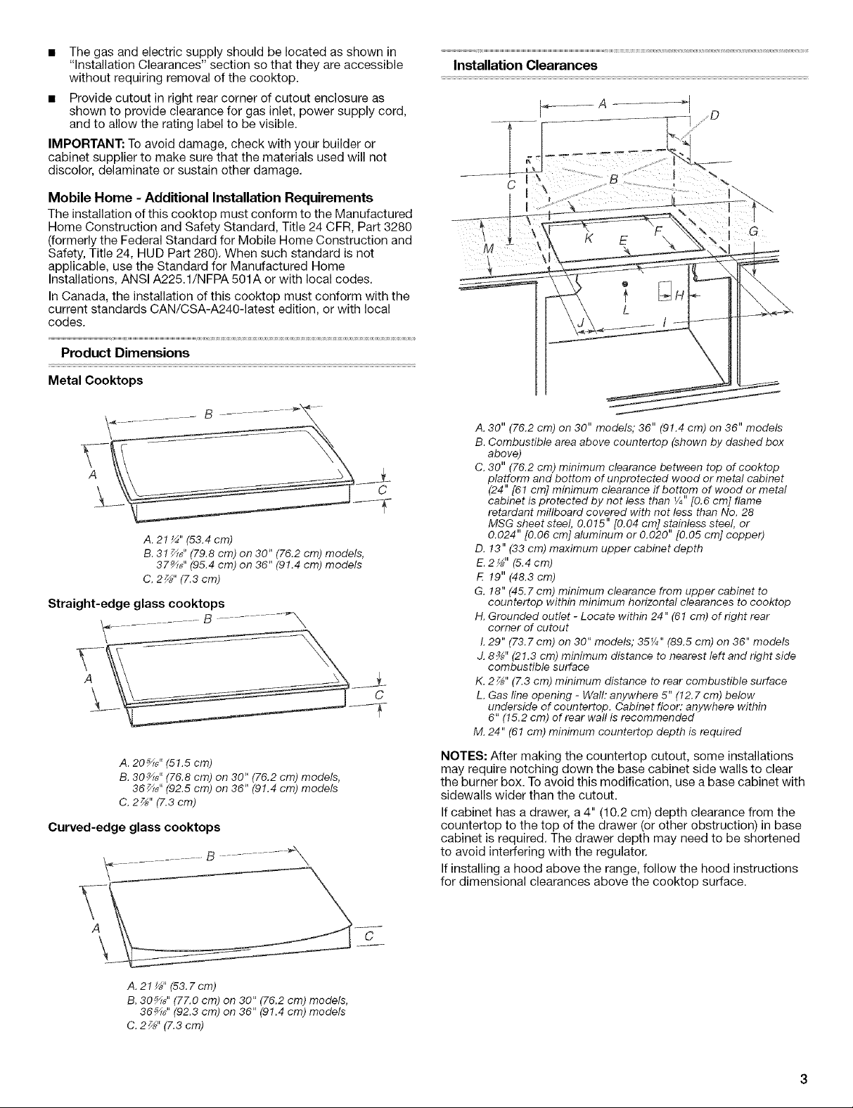
Product Dimensions
Metal Cooktops
\ c
A. 21_" (53.4 cm)
B. 31 _6" (79.8 cm) on 30" (76.2 cm) models,
37_G" (95.4 cm) on 36" (91.4 cm) models
C. 2z_'' (7.3 cm)
Straight-edge glass cooktops
C
Installation Clearances
A. 30" (76.2 cm) on 30" models," 36" (91.4 cm) on 36" models
B. Combustible area above countertop (shown by dashed box
above)
C. 30" (76.2 cm) minimum clearance between top of coektop
platform and bottom of unprotected wood or metal cabinet
(24" [61 cm] minimum clearance if bottom of wood er metal
cabinet is protected by not less than V4"[0.6 cm] flame
retardant mlllboard covered with not less than No. 28
MSG sheet steel, 0.015" [0.04 cm] stainless steel, or
0.024" [0.06 cm] aluminum or 0.020" [0.05 cm] copper)
D. !3" (33 cm) maximum upper cabinet depth
E. 2_" (5.4cm)
!9" (48.3 cm)
G. 18" (45.7 cm) minimum clearance from upper cabinet to
countertop within minimum horizontal clearances to cooktop
H. Grounded outlet - Locate within 24" (61 cm) of right rear
corner of cutout
L 29" (73.7 cm) on 30" models; 35¼" (89.5 cm) on 36" models
J. 8_;" (21.3 cm) minimum distance to nearest left and right side
combustible surface
K. 2_" (7.3 cm) minimum distance to rear combustible surface
L. Gas line opening - Wall: anywhere 5" (12.7 cm) below
underside of countertop. Cabinet floor: anywhere within
6" (15.2 cm) of rear wall is recommended
M. 24" (61 cm) minimum countertop depth is required
A. 20_" (51.5 cm)
B. 30_" (76.8 cm) on 30" (76.2 cm) models,
36_" (92.5 cm) on 36" (91.4 cm) models
C. 2Z_" (7.3 cm)
Curved-edge glass cooktops
.......... B' - ............ _'X
A. 21_" (53.Z cm)
B. 30_" (77.0 cm) on 30" (76.2 cm) models,
36_" (92.3 cm) on 36" (91.4 cm) models
C. 2 _" (7.3 cm)
NOTES: After making the countertop cutout, some installations
may require notching down the base cabinet side walls to clear
the burner box. Toavoid this modification, use a base cabinet with
sidewalls wider than the cutout.
If cabinet has a drawer, a 4" (10.2 cm) depth clearance from the
countertop to the top of the drawer (or other obstruction) in base
cabinet is required. The drawer depth may need to be shortened
to avoid interfering with the regulator.
If installing a hood above the range, follow the hood instructions
for dimensional clearances above the cooktop surface.
EmectricatShockHazard
Plugintoagrounded3prongoutlet.
Donotremovegroundprong.
Donotuseanadapter.
Donotuseanextension cord.
Faimureto follow these instructions can resumt in death,
fire, or emectrical shock.
IMPORTANT: The cooktop must be electrically grounded in
accordance with local codes and ordinances, or in the absence of
local codes, with the National Electrical Code, ANSI/NFPA 70 or
Canadian Electrical Code, CSA C22.1.
This cooktop is equipped with an electronic ignition system that
will not operate if plugged into an outlet that is not properly
polarized.
If codes permit and a separate ground wire is used, it is
recommended that a qualified electrical installer determine that
the ground path is adequate.
A copy of the above code standards can be obtained from:
National Fire Protection Association
One Batterymarch Park
Quincy, MA 02269
CSA International
8501 East Pleasant Valley Road
Cleveland, OH 44131-5575
• A 120 volt, 60 Hz., AC only, 15-amp fused, electrical circuit is
required. A time-delay fuse or circuit breaker is also
recommended. It is recommended that a separate circuit
serving only this cooktop be provided.
• Electronic ignition systems operate within wide voltage limits,
but proper grounding and polarity are necessary. Check that
the outlet provides 120 volt power and is correctly grounded.
• The wiring diagrams are provided with this cooktop. See
"Wiring Diagrams" section.
Explosion Hazard
Use a new CSA gnternational approved gas supply mine.
Install a shut-off valve.
Securety tighten all gas connections,
ff connected to LP, have a qua{ified person make sure
gas pressure does not exceed 14" (36 cm) water
comumn,
Exampmes of a quamified person include:
licensed heating personneB,
authorized gas company personnel, and
authorized service personnel
Failure to do so can result in death, explosion, or fire.
Observe all governing codes and ordinances.
IMPORTANT: This installation must conform with all local codes
and ordinances. Inthe absence of local codes, installation must
conform with American National Standard, National Fuel Gas
Code ANSI Z223.1 - latest edition or CAN/CGA B149 - latest
edition.
Type of Gas
Natural Gas:
This cooktop is design-certified by the CSA International for use
with Natural gas or, after proper conversion, for use with LP gas.
• This cooktop is factory set for use with Natural gas. To convert
to LP gas, see the Gas Conversion instructions provided in the
literature package. The model/serial rating plate located on
the underside of the burner box has information on the types
of gas that can be used. If the types of gas listed do not
include the type of gas available, check with the local gas
supplier.
LP Gas conversion:
Conversion must be done by a qualified service technician.
No attempt shall be made to convert the appliance from the gas
specified on the model/serial rating plate for use with a different
gas without consulting the serving gas supplier. See the Gas
Conversion instructions provided in the literature package.
Gas Supply Line
• Provide a gas supply line of 3/4"(1.9 cm) rigid pipe to the
cooktop location. A smaller size pipe on longer runs may
result in insufficient gas supply. Pipe-joint compounds that
resist the action of LP gas must be used. Do not use
TEFLON _t tape. With LP gas, piping or tubing size can be 1/2"
minimum. Usually, LP gas suppliers determine the size and
materials used in the system.
1-CeTEFLON is a registered trademark of E.I. Du Pont De Nemours and Company.
Flexible metal appliance connector:
• If local codes permit, use a 1/2"or 3/4"I.D. flexible stainless
steel tubing gas connector, designed by CSA to connect
the cooktop to the rigid gas supply line.
• A %" male pipe thread is needed for connection to the
female pipe threads of the inlet to the appliance pressure
regulator.
• Do not kink or damage the flexible metal tubing when
moving the cooktop.
Rigid pipe connection:
The rigid pipe connection requires a combination of pipe
fittings to obtain an in-line connection to the cooktop. The
rigid pipe must be level with the cooktop connection. All
strains must be removed from the supply and fuel lines so
cooktop will be level and in line.
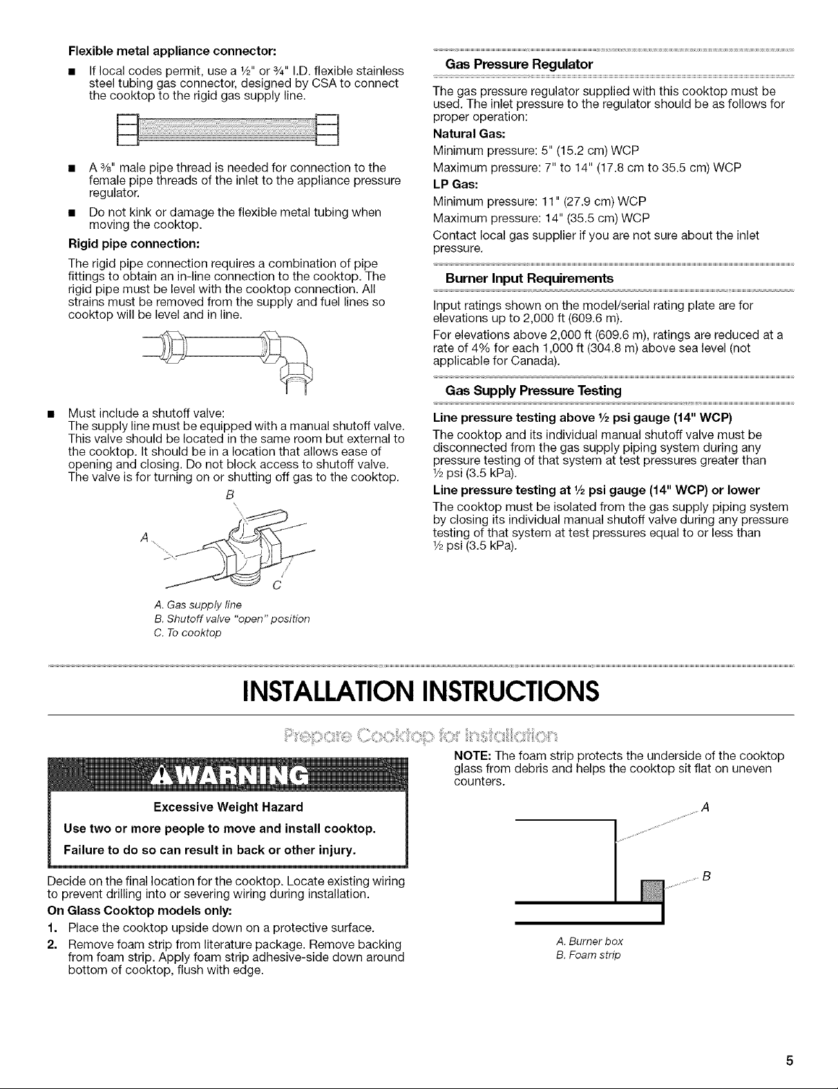
Must include a shutoff valve:
The supply line must be equipped with a manual shutoff valve.
This valve should be located in the same room but external to
the cooktop. It should be in a location that allows ease of
opening and closing. Do not block access to shutoff valve.
The valve is for turning on or shutting off gas to the cooktop.
B
Gas Pressure Regulator
The gas pressure regulator supplied with this cooktop must be
used. The inlet pressure to the regulator should be as follows for
proper operation:
Natural Gas:
Minimum pressure: 5" (15.2 cm) WCP
Maximum pressure: 7" to 14" (17.8 cm to 35.5 cm) WCP
LP Gas:
Minimum pressure: 11" (27.9 cm) WCP
Maximum pressure: 14" (35.5 cm) WCP
Contact local gas supplier if you are not sure about the inlet
pressure.
Burner Input Requirements
Input ratings shown on the model/serial rating plate are for
elevations up to 2,000 ft (609.6 m).
For elevations above 2,000 ft (609.6 m), ratings are reduced at a
rate of 4% for each 1,000 ft (304.8 m) above sea level (not
applicable for Canada).
Gas Supply Pressure Testing
Line pressure testing above 1/2psi gauge (14" WCP)
The cooktop and its individual manual shutoff valve must be
disconnected from the gas supply piping system during any
pressure testing of that system at test pressures greater than
1/2psi (3.5 kPa).
Line pressure testing at 1/2psi gauge (14" WCP) or lower
The cooktop must be isolated from the gas supply piping system
by closing its individual manual shutoff valve during any pressure
testing of that system at test pressures equal to or less than
1/2psi (3.5 kPa).
C
A.Gas supply line
B.Shutoff valve "open" position
C. Tocooktop
INSTALLATIONINSTRUCTIONS
Decide on the final location for the cooktop. Locate existing wiring
to prevent drilling into or severing wiring during installation.
On Glass Cooktop models only:
1. Place the cooktop upside down on a protective surface.
2. Remove foam strip from literature package. Remove backing
from foam strip. Apply foam strip adhesive-side down around
bottom of cooktop, flush with edge.
NOTE: The foam strip protects the underside of the cooktop
glass from debris and helps the cooktop sit flat on uneven
counters.
A. Burner box
B. Foam strip
Style 1: Cooktop over undercounter built-in oven
IMPORTANT: Clamp brackets should not be used.
1. Place cooktop right side up into the cutout.
NOTE: Make sure that the front edge of the cooktop is parallel
to the front edge of the countertop. If repositioning is needed,
lift entire cooktop up from cutout to prevent scratching the
countertop.
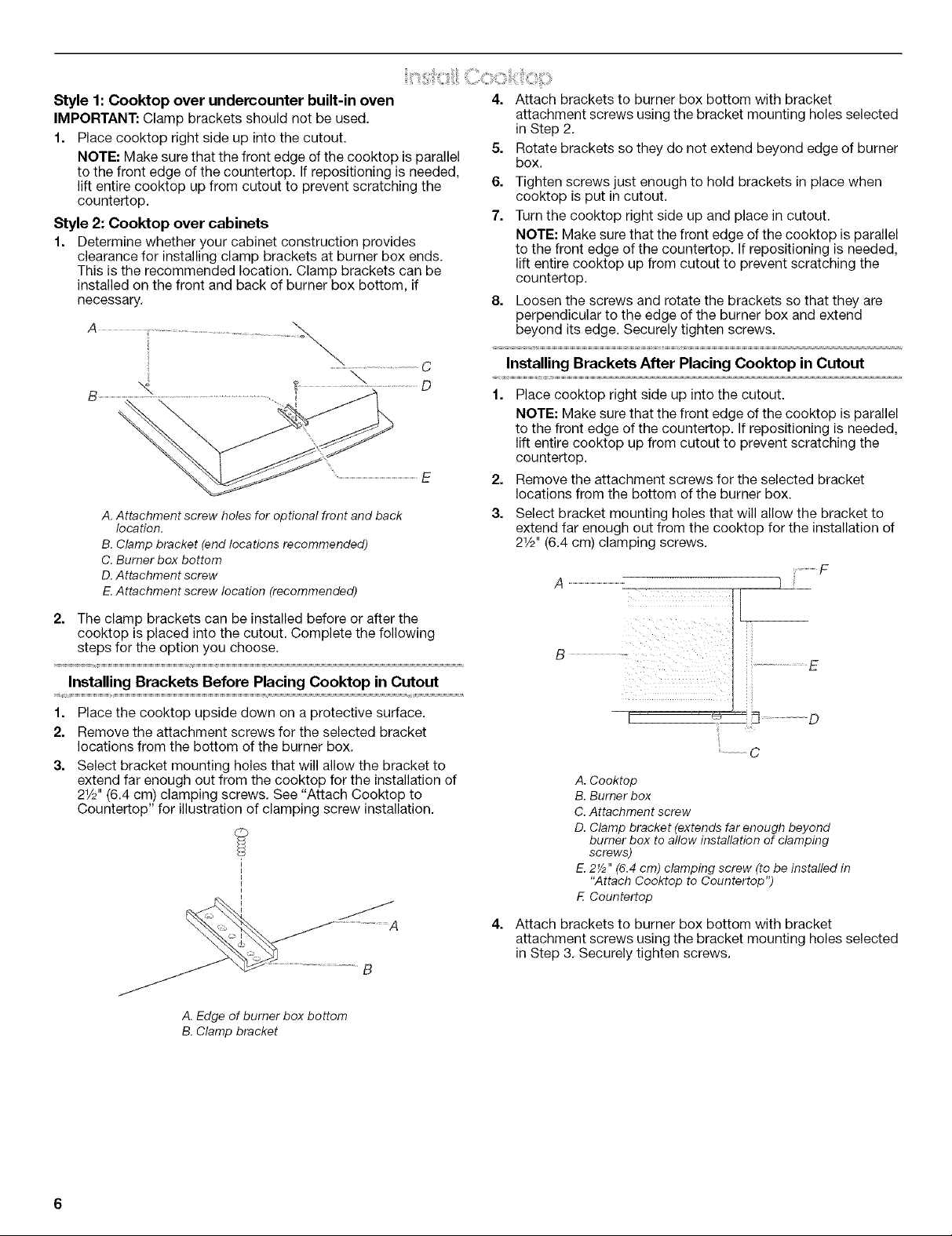
Style 2: Cooktop over cabinets
1. Determine whether your cabinet construction provides
clearance for installing clamp brackets at burner box ends.
This is the recommended location. Clamp brackets can be
installed on the front and back of burner box bottom, if
necessary,
A. Attachment screw holes for optional front and back
location.
B. Clamp bracket (end locations recommended)
C. Burner box bottom
D. Attachment screw
E.Attachment screw location (recommended)
4. Attach brackets to burner box bottom with bracket
attachment screws using the bracket mounting holes selected
in Step 2.
5. Rotate brackets so they do not extend beyond edge of burner
box.
6. Tighten screws just enough to hold brackets in place when
cooktop is put in cutout.
7. Turn the cooktop right side up and place in cutout.
NOTE: Make sure that the front edge of the cooktop is parallel
to the front edge of the countertop. If repositioning is needed,
lift entire cooktop up from cutout to prevent scratching the
countertop,
8. Loosen the screws and rotate the brackets so that they are
perpendicular to the edge of the burner box and extend
beyond its edge. Securely tighten screws.
Installing Brackets After Placing Cooktop in Cutout
1. Place cooktop right side up into the cutout.
NOTE: Make sure that the front edge of the cooktop is parallel
to the front edge of the countertop. If repositioning is needed,
lift entire cooktop up from cutout to prevent scratching the
countertop.
2. Remove the attachment screws for the selected bracket
locations from the bottom of the burner box.
3. Select bracket mounting holes that will allow the bracket to
extend far enough out from the cooktop for the installation of
21/2'' (6.4 cm) clamping screws.
F
A )
2. The clamp brackets can be installed before or after the
cooktop is placed into the cutout. Complete the following
steps for the option you choose,
Installing Brackets Before Placing Cooktop in Cutout
1. Place the cooktop upside down on a protective surface.
2. Remove the attachment screws for the selected bracket
locations from the bottom of the burner box.
3. Select bracket mounting holes that will allow the bracket to
extend far enough out from the cooktop for the installation of
21/2'' (6.4 cm) clamping screws, See "Attach Cooktop to
Countertop" for illustration of clamping screw installation,
A
A. Edge of burner box bottom
B. Clamp bracket
E
__ D
C
A. Cooktop
B. Burner box
C.Attachment screw
D. Clamp bracket (extends far enough beyond
burner box to allow installation of clamping
screws)
E. 2Y2" (6.4 cm) clamping screw (to be installed in
"Attach Cooktop to Countertop")
F. Countertop
Attach brackets to burner box bottom with bracket
attachment screws using the bracket mounting holes selected
in Step 3, Securely tighten screws.
 Loading...