

Whirlpool GI15NFRTB0, GI15NFLTS1, GI15NFLTB0, GI15NDXTB0, GI15NFRTS1 Owner’s Manual
...
ICEMAKER
_illY:_,_i:!__i!ii_:i_i:ii':!_ii_i_:_'_ili!iif!fill¸!:_i:i,i_!::!ii_:i!!_
For questions about features, operation/performance,
parts, accessories or service, call: 1-800-253-1301.
In Canada, call for assistance 1-800-461-5681, for installation
www.whirlpool.com or www.whirlpoolappliances.ca
and service, call: 1-800-807-6777
or visit our website at...
MACHINEAGLA(_ONS
Au Canada, pour assistance, composez le 1-800-461-5681, pour
Table of Contents/Table des matieres .................. 2
installation ou service, le 1-800-807-6777
ou visitez notre site web &
www.whirlpoolappliances.ca
2313683A
TABLEOFCONTENTS
ICE MAKER SAFETY ...................................................................... 3
INSTALLATION INSTRUCTIONS .................................................. 3
Unpack the Ice Maker .................................................................. 3
Location Requirements ................................................................ 4
Electrical Requirements ............................................................... 4
Water Supply Requirements ........................................................ 4
Leveling ........................................................................................ 5
Connect Water Supply ................................................................. 5
Drain Connection ......................................................................... 6
Ice Maker Door ............................................................................. 7
Normal Sounds ............................................................................ 8
ICE MAKER USE ............................................................................ 8
How Your Ice Maker Works ......................................................... 8
Using the Controls ....................................................................... 9
TABLEDESMATIERES
S¢:CURIT¢: DE LA MACHINE A GLAQONS ................................ 15
INSTRUCTIONS D'INSTALLATION ............................................ 15
Deballage de la machine h gla(_ons........................................... 15
Exigences d'emplacement ......................................................... 16
Specifications electriques .......................................................... 16
Specifications de I'alimentation en eau ..................................... 16
Nivellement ................................................................................. 17
Raccordement a la canalisation d'eau ...................................... 17
Raccordement au conduit d'evacuation ................................... 18
Porte de la machine a glagons .................................................. 19
Sons normaux ............................................................................ 20
UTILISATION DE LA MACHINE A GLA(_ONS ............................ 21
Fonctionnement de la machine a gla(_ons................................. 21
Utilisation des commandes ........................................................ 21
ICE MAKER CARE .......................................................................... g
Cleaning ........................................................................................ 9
Vacation and Moving Care ......................................................... 11
TROUBLESHOOTING .................................................................. 12
Ice Maker Operation ................................................................... 12
Ice Production ............................................................................ 12
Ice Quality ................................................................................... 13
Plumbing Problems .................................................................... 13
ASSISTANCE OR SERVICE ......................................................... 13
In the U.S.A................................................................................ 13
In Canada ................................................................................... 13
WAR RANTY .................................................................................. 14
ENTRETIEN DE LA MACHINE ._,GLA_ONS .............................. 22
Nettoyage ................................................................................... 22
Precautions h prendre avant les vacances
ou un demenagement ................................................................ 24
DEPANNAGE ................................................................................. 25
Fonctionnement de la machine a gla(_ons................................. 25
Production de gla(_ons ............................................................... 25
Qualite des gla(_ons.................................................................... 26
Problemes de plomberie ............................................................ 26
ASSISTANCE OU SERVICE ......................................................... 26
GARANTIE ..................................................................................... 27
ICEMAKERSAFETY
Your safety and the safety of others are very important.
We have provided many important safety messages in this manual and on your appliance. Always read and obey all safety
messages.
This is the safety alert symbol.
This symbol alerts you to potential hazards that can kill or hurt you and others.
All safety messages will follow the safety alert symbol and either the word "DANGER" or "WARNING."
These words mean:
You can be killed or seriously injured if you don't immediately
follow instructions.
You can be killed or seriously injured if you don't follow
instructions.
All safety messages will tell you what the potential hazard is, tell you how to reduce the chance of injury, and tell you what can
happen if the instructions are not followed.
IMPORTANT SAFETY INSTRUCTIONS
WARNING: To reduce the risk of fire, electric shock, or injury when using your ice maker, follow these basic
precautions:
• Plug into a grounded 3 prong outlet.
• Do not remove ground prong.
• Do not use an adapter.
• Do not use an extension cord.
• Disconnect power before cleaning.
• Disconnect power before servicing.
• Replace all parts and panels before operating.
• Use two or more people to move and install ice maker.
SAVE THESE INSTRUCTIONS
INSTALLATIONINSTRUCTIONS
Do not use sharp instruments, rubbing alcohol, flammable
fluids, or abrasive cleaners to remove tape or glue. Do not
use chlorine bleach on the stainless steel surfaces of the ice
Excessive Weight Hazard
Use two or more people to move and install ice maker.
Failure to do so can result in back or other injury.
Removing Packaging Materials
_, ..............................................................................................................................................................................................................................................................................................................................................................................................................................the "Ice Maker Care" section.
Remove tape and glue from your ice maker before using.
• To remove any remaining tape or glue from the exterior of the
ice maker, rub the area briskly with your thumb. Tape or glue
residue can also be easily removed by rubbing a small
amount of liquid dish soap over the adhesive with your
fingers. Wipe with warm water and dry.
maker. These products can damage the surface of your ice
maker.
Cleaning Before Use
After you remove all of the packaging materials, clean the inside
of your ice maker before using it. See the cleaning instructions in
,,_i:¸_c_ilti:ili_:_;_ii__::_iii!_ii_¸_ _/_iii_ii_,_;!!!%ii__:!!_ii:i__i:!i;
To ensure proper ventilation for your ice maker, the front side
must be completely unobstructed. The unit may be closed-in
on the top and three sides, but the installation should allow
the ice maker to be pulled forward for servicing if necessary.
Installation of the ice maker requires a cold water supply inlet
of 1/4"(6.35 mm) OD soft copper tubing with a shutoff valve
and either a gravity-drain system or condensate pump to
carry the water to an existing drain.
Choose a well ventilated area with temperatures above 55°F
(13°C) and below 110°F (43°C). Best results are obtained
between 70°F (21 °C) and 90°F (32°C).
This unit must be installed in an area protected from the
elements, such as wind, rain, water spray, or drip.
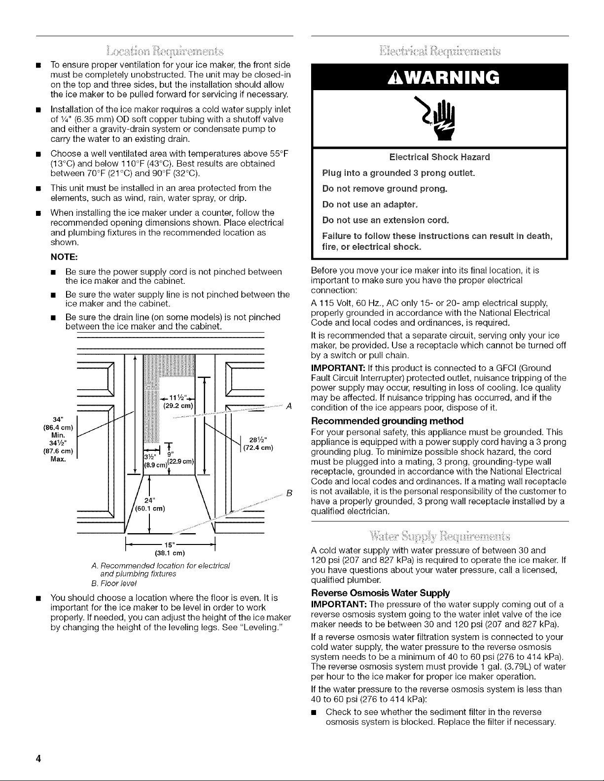
When installing the ice maker under a counter, follow the
recommended opening dimensions shown. Place electrical
and plumbing fixtures in the recommended location as
shown.
NOTE:
• Be sure the power supply cord is not pinched between
the ice maker and the cabinet.
• Be sure the water supply line is not pinched between the
ice maker and the cabinet.
• Be sure the drain line (on some models) is not pinched
between the ice maker and the cabinet.
_0
34"
(86.4 cm)
Min.
341/2"
(87.6 cm)
Max.
1
281/2"
(72.4 cm)
Electricam Shock Hazard
Pmuginto a grounded 3 prong outlet.
Do not remove ground prong.
Do not use an adapter.
Do not use an extension cord.
Failure to follow these instructions can resumt in death,
fire, or eiectricam shock.
Before you move your ice maker into its final location, it is
important to make sure you have the proper electrical
connection:
A 115 Volt, 60 Hz., AC only 15- or 20- amp electrical supply,
properly grounded in accordance with the National Electrical
Code and local codes and ordinances, is required.
It is recommended that a separate circuit, serving only your ice
maker, be provided. Use a receptacle which cannot be turned off
by a switch or pull chain.
IMPORTANT: If this product is connected to a GFCI (Ground
Fault Circuit Interrupter) protected outlet, nuisance tripping of the
power supply may occur, resulting in loss of cooling. Ice quality
may be affected. If nuisance tripping has occurred, and if the
condition of the ice appears poor, dispose of it.
Recommended grounding method
For your personal safety, this appliance must be grounded. This
appliance is equipped with a power supply cord having a 3 prong
grounding plug. To minimize possible shock hazard, the cord
must be plugged into a mating, 3 prong, grounding-type wall
receptacle, grounded in accordance with the National Electrical
Code and local codes and ordinances. Ifa mating wall receptacle
is not available, it is the personal responsibility of the customer to
B
have a properly grounded, 3 prong wall receptacle installed by a
qualified electrician.
(38,1 cm)
A.Recommended location for electrical
andplumbing fixtures
B.Floor level
You should choose a location where the floor is even. It is
important for the ice maker to be level in order to work
properly. If needed, you can adjust the height of the ice maker
by changing the height of the leveling legs. See "Leveling."
A cold water supply with water pressure of between 30 and
120 psi (207 and 827 kPa) is required to operate the ice maker. If
you have questions about your water pressure, call a licensed,
qualified plumber.
Reverse Osmosis Water Supply
IMPORTANT: The pressure of the water supply coming out of a
reverse osmosis system going to the water inlet valve of the ice
maker needs to be between 30 and 120 psi (207 and 827 kPa).
If a reverse osmosis water filtration system is connected to your
cold water supply, the water pressure to the reverse osmosis
system needs to be a minimum of 40 to 60 psi (276 to 414 kPa).
The reverse osmosis system must provide 1 gal. (3.79L) of water
per hour to the ice maker for proper ice maker operation.
If the water pressure to the reverse osmosis system is less than
40 to 60 psi (276 to 414 kPa):
• Check to see whether the sediment filter in the reverse
osmosis system is blocked. Replace the filter if necessary.
• Allowthestoragetankonthereverseosmosissystemtorefill
afterheavyusage.
Ifyouhavequestionsaboutyourwaterpressure,callalicensed,
qualifiedplumber.
Itisimportantfortheicemakertobelevelinordertowork
properly.Dependinguponwhereyouinstalltheicemaker,you
mayneedtomakeseveraladjustmentstolevelit.Youmayalso
usethelevelinglegstolowertheheightoftheicemakerfor
undercounterinstallations.
Tools needed:
Gather the required tools and parts before starting installation.
• 9" level
• Adjustable wrench
NOTE: It is easier to adjust the leveling legs if you have another
person to assist you.
1. Move the ice maker to its final location.
NOTE: If this is a built-in installation, move the ice maker as
close as possible to the final location.
2. Place a carpenter's level on top of the product to see if the ice
maker is level from front to back and side to side.
3. Push up on the top front of the ice maker, and then locate the
leveling screws that are on the bottom front of the ice maker.
4. Using an adjustable wrench, change the height of the legs as
follows:
• Turn the leveling leg to the right to lower that side of the
ice maker.
• Turn the leveling leg to the left to raise that side of the ice
maker.
NOTE: The ice maker should not wobble. Use shims to add
stability when needed.
5. Push up on the top rear of the ice maker and locate the
leveling legs that are on the bottom rear of the ice maker.
6. Follow the instructions in Step 4 to change the height of the
legs.
7. Use a carpenter's level to recheck the ice maker to see that it
is even from front to back and side to side. If the ice maker is
not level, repeat steps 2 to 5. Ifthe ice maker is level, go to
the "Connect Water Supply" section.
• Flat-blade screwdriver
• 7/16"and 1/2"open-end wrenches or two adjustable wrenches
• 1/4"nut driver
• 1/4"drill bit
• Hand drill or electric drill properly grounded
NOTE: Your ice maker dealer has a kit available with a 1/4"
(6.35 mm) saddle-type shutoff valve, a union, and copper tubing.
Before purchasing, make sure a saddle-type valve complies with
your local plumbing codes. Do not use a piercing-type or 3/16"
(4.76 mm) saddle valve which reduces water flow and clogs more
easily.
Connecting the water line
1.
Turn off main water supply. Turn on nearest faucet long
enough to clear line of water.
2.
Find a 1/2"(12.70 mm) to 11/4'' (3.18 cm) vertical cold water
pipe near the ice maker.
NOTE: Horizontal pipe will work, but the following procedure
must be followed: Drill on the top side of the pipe, not the
bottom. This will help keep water away from the drill. This
also keeps normal sediment from collecting in the valve.
3. Using a grounded drill, drill a 1/4"(6.35 mm) hole in the cold
water pipe you have selected.
4. Fasten shutoff valve to cold water pipe with pipe clamp. Be
sure outlet end is solidly in the 1/4"(6.35 mm) drilled hole in the
water pipe and that the washer is under the pipe clamp.
Tighten packing nut. Tighten the pipe clamp screws carefully
and evenly so washer makes a watertight seal. Do not
overtighten the pipe clamp or you may crush cold water pipe
if it is soft copper tubing. Do not use a piercing-type or 3/16"
(4.76 mm) saddle-type valve which reduces water flow and
clogs more easily.
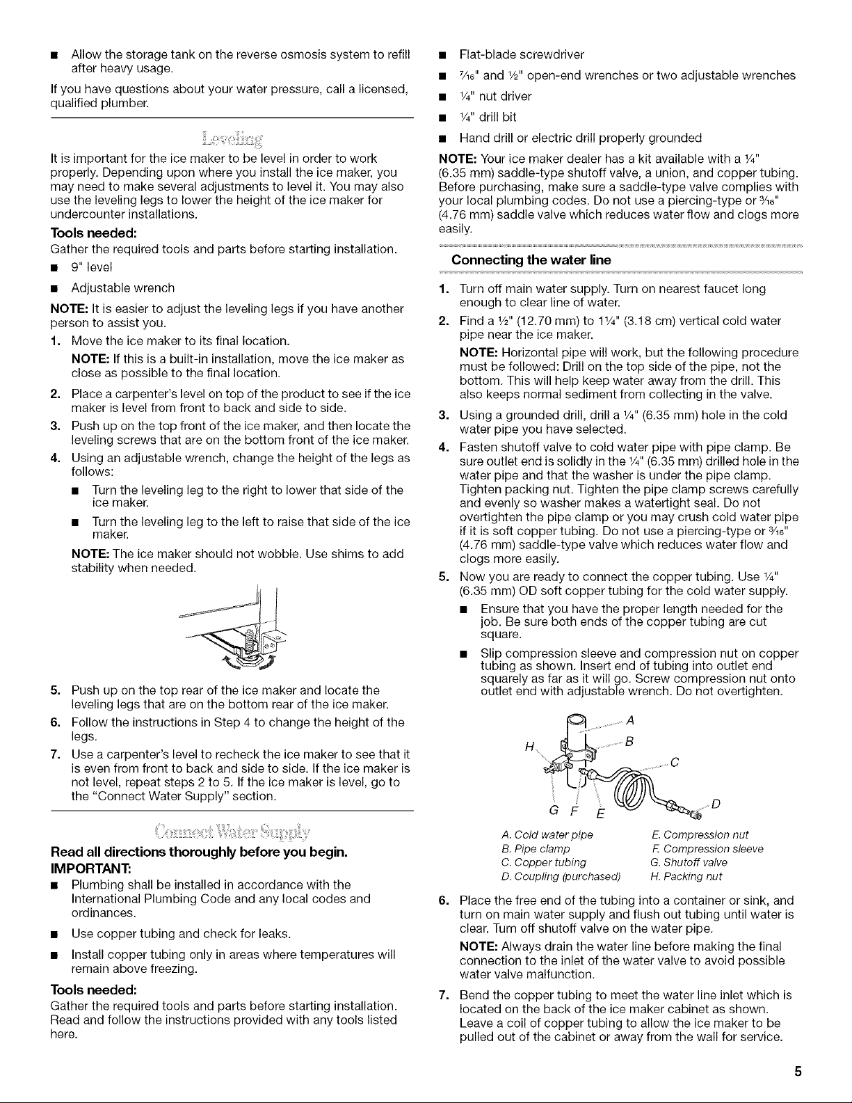
5. Now you are ready to connect the copper tubing. Use 1/4"
(6.35 mm) OD soft copper tubing for the cold water supply.
• Ensure that you have the proper length needed for the
job. Be sure both ends of the copper tubing are cut
square.
• Slip compression sleeve and compression nut on copper
tubing as shown. Insert end of tubing into outlet end
squarely as far as it will go. Screw compression nut onto
outlet end with adjustable wrench. Do not overtighten.
............... ,,,,,,,,, C
Read all directions thoroughly before you begin.
IMPORTANT:
• Plumbing shall be installed in accordance with the
International Plumbing Code and any local codes and
ordinances.
• Use copper tubing and check for leaks.
• Install copper tubing only in areas where temperatures will
remain above freezing.
Tools needed:
Gather the required tools and parts before starting installation.
Read and follow the instructions provided with any tools listed
here.
A.Cold water pipe E.Compression nut
B.Pipe clamp E Compression sleeve
C.Copper tubing G.Shutoff valve
D.Coupling (purchased) H.Packing nut
6.
Place the free end of the tubing into a container or sink, and
turn on main water supply and flush out tubing until water is
clear. Turn off shutoff valve on the water pipe.
NOTE: Always drain the water line before making the final
connection to the inlet of the water valve to avoid possible
water valve malfunction.
7.
Bend the copper tubing to meet the water line inlet which is
located on the back of the ice maker cabinet as shown.
Leave a coil of copper tubing to allow the ice maker to be
pulled out of the cabinet or away from the wall for service.
REAR VIEW
SIDE VIEW
A
B
@
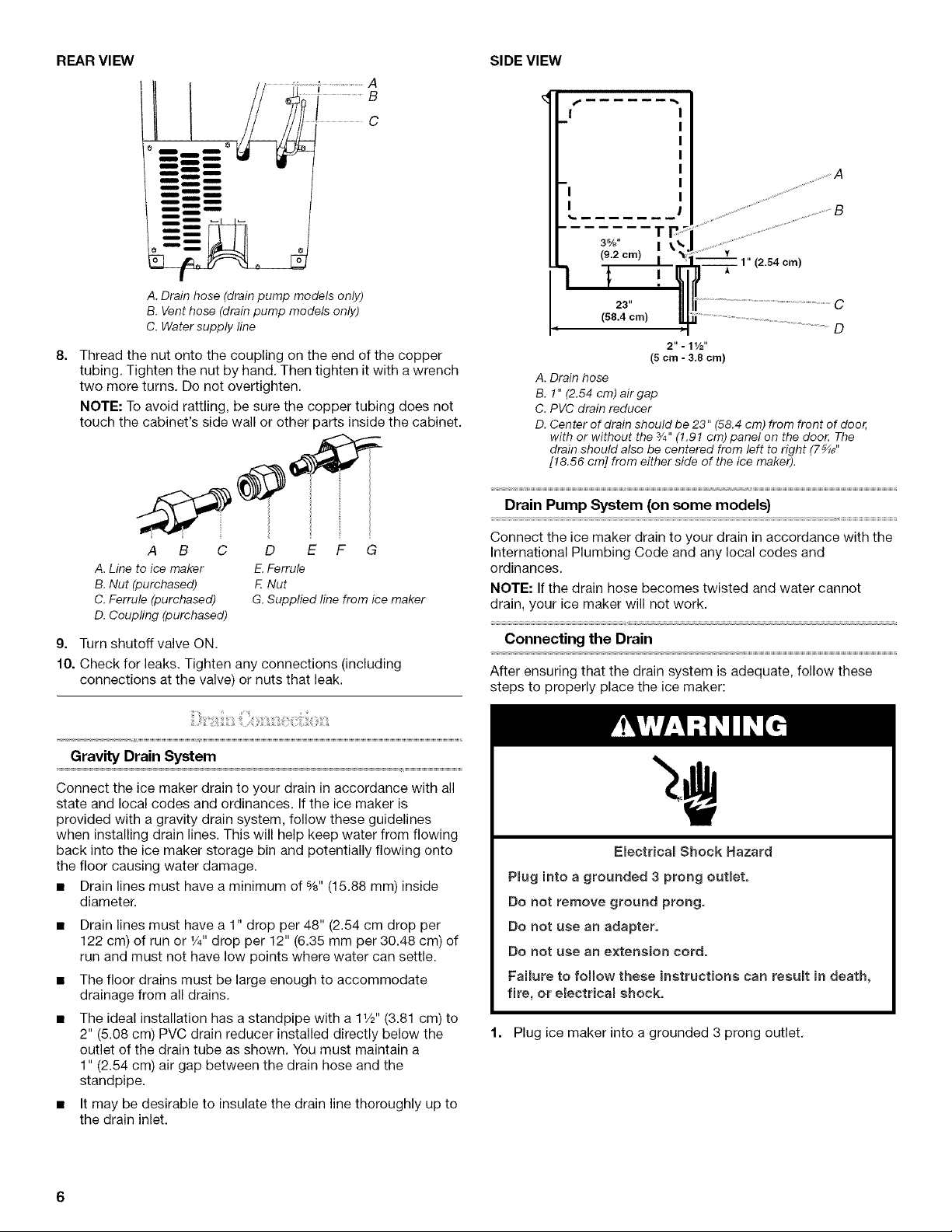
A. Drain hose (drain pump models only)
B. Vent hose (drain pump models only)
C. Water supply line
8.
Thread the nut onto the coupling on the end of the copper
tubing. Tighten the nut by hand. Then tighten it with a wrench
two more turns. Do not overtighten.
NOTE: To avoid rattling, be sure the copper tubing does not
touch the cabinet's side wall or other parts inside the cabinet.
A B C
A.Line to ice maker
B.Nut (purchased)
C.Ferrule (purchased)
D F o
E.Ferrule
F Nut
G.Supplied line from ice maker
D. Coupling (purchased)
g. Turn shutoff valve ON.
10. Check for leaks. Tighten any connections (including
connections at the valve) or nuts that leak.
3%"
(9.2 cm)
1"
I
23" C
(58,4 cm)
2". 11/2''
(5 cm - 3.8 cm)
A. Drain hose
B. 1" (2.54 cm) air gap
C. PVC drain reducer
D. Center of drain should be 23" (58.4 cm) from front of door,
with or without the 3/4"(1.91 cm) panel on the door: The
drain should also be centered from left to right (7 _J'
[18.56 cm] from either side of the ice maker).
D
Drain Pump System (on some models)
Connect the ice maker drain to your drain in accordance with the
International Plumbing Code and any local codes and
ordinances.
NOTE: If the drain hose becomes twisted and water cannot
drain, your ice maker will not work.
Connecting the Drain
After ensuring that the drain system is adequate, follow these
steps to properly place the ice maker:
Gravity Drain System
Connect the ice maker drain to your drain in accordance with all
state and local codes and ordinances. If the ice maker is
provided with a gravity drain system, follow these guidelines
when installing drain lines. This will help keep water from flowing
back into the ice maker storage bin and potentially flowing onto
the floor causing water damage.
• Drain lines must have a minimum of %" (15.88 mm) inside
diameter.
• Drain lines must have a 1" drop per 48" (2.54 cm drop per
122 cm) of run or 1/4"drop per 12" (6.35 mm per 30.48 cm) of
run and must not have low points where water can settle.
• The floor drains must be large enough to accommodate
drainage from all drains.
The ideal installation has a standpipe with a 11/2"(3.81 cm) to
2" (5.08 cm) PVC drain reducer installed directly below the
outlet of the drain tube as shown. You must maintain a
1" (2.54 cm) air gap between the drain hose and the
standpipe.
• It may be desirable to insulate the drain line thoroughly up to
the drain inlet.
Electdca_ Shock Hazard
P_ug into a grounded 3 prong outlet.
Do not remove ground prong.
Do not use an adapter.
Do not use an extension cord.
Failure to follow these instructions can result in death,
fire, or electrica_ shock,
1. Plug ice maker into a grounded 3 prong outlet.
2. Style 1 - For gravity drain system, push the ice maker into
position so that the ice maker drain tube is positioned over
the PVC drain reducer. See "Gravity Drain System" earlier in
this section. Style 2 - For drain pump system connect the
drain pump outlet hose to the drain. See "Drain Pump
System" earlier in this section.
3. Recheck the ice maker to be sure that it is level. See
"Leveling."
4. If it is required by your local sanitation code, seal the cabinet
to the floor with an approved caulking compound after all
water and electrical connections have been made.
Reverse Hinges
1. Unscrew and remove the top hinge. Replace the screws in
the empty hinge holes.
2. Remove the screws from the bottom of the opposite side of
the ice maker cabinet. Turn the top hinge upside down so
that the hinge pin points up. Place the hinge on the bottom
opposite side of the ice maker and tighten screws.
3. Remove the plastic hinge pin sleeve from the "old" bottom
hinge and replace it on the new bottom hinge pin.
4. Remove the "old" bottom hinge screws and hinge. Replace
the screws in the empty hinge holes.
5. Remove the screws from the top of the opposite side of the
ice maker cabinet. Turn the hinge upside down so that the
hinge pin points down. Place the hinge on the top opposite
side of the ice maker and tighten the screws.
6. Remove the top hinge pin.
Replace Door
TOOLS NEEDED:
Gather the required tools and parts before starting installation.
• %6" wrench • Flat putty knife
• 1/4"wrench • Phillips screwdriver
Hinge pin
5/16"Hex-head hinge screw
Handlescrew End Capscrew
Remove door
1. Unplug ice maker or disconnect power.
2. Remove the handle screws and handle (on some models).
Keep the parts together and set them aside.
3. Remove the hinge pin from the top hinge.
4. Remove the door from the hinges and screw the top hinge pin
back into the top hinge.
5. Reverse the door endcaps as follows:
• Remove both the screws and endcaps (top and bottom).
• Move the top end cap diagonally to the opposite side's
bottom corner, keeping the straight side of the end cap
facing the front of the ice maker.
• Move the bottom end cap diagonally to the opposite
side's top corner, keeping the straight side of the end cap
facing the front of the ice maker.
6. Set the door aside.
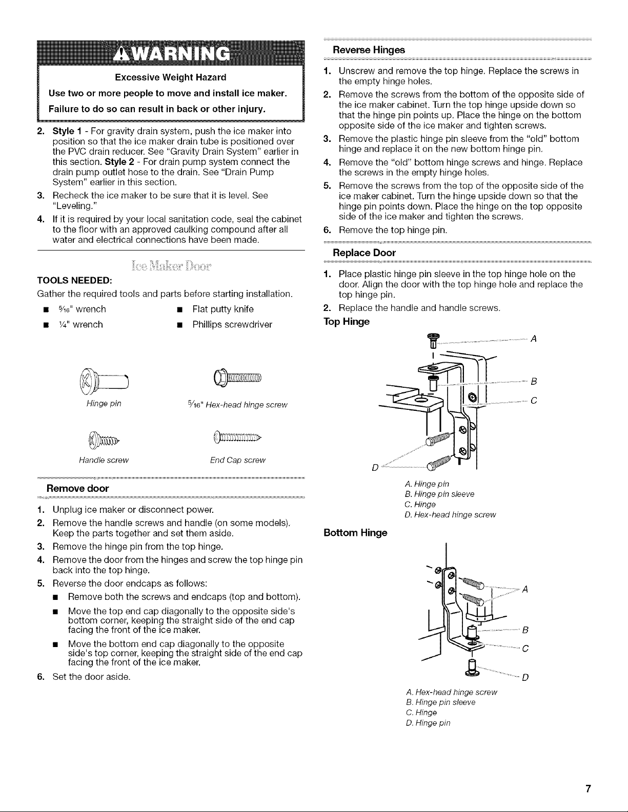
1. Place plastic hinge pin sleeve in the top hinge hole on the
door. Align the door with the top hinge hole and replace the
top hinge pin.
2. Replace the handle and handle screws.
Top Hinge
......................................A
A. Hinge pin
B. Hinge pin sleeve
C. Hinge
D. Hex-head hinge screw
Bottom Hinge
j
........................................................O
A.Hex-head hinge screw
B. Hingepin sleeve
C. Hinge
D. Hingepin
Reverse Door Catch
1. Remove the hole plugs from the opposite side of the door
and set aside.
2. Remove the screws from the magnetic door catch and
replace it on the opposite side of the door.
3. Push the hole plugs into place on the opposite side of the
door.
E_ectrica_ Shock Hazard
Plug into a grounded 3 prong outlet.
Do not remove ground prong.
Do not use an adapter.
Do not use an extension cord.
Failure to follow these instructions can result in death,
fire, or e_ectrica{ shock.
ICEMAKERUSE
When you first start your ice maker, the water pan will fill and the
system will rinse itself before starting to make ice. The rinsing
process takes about 5 minutes.
Under normal operating conditions, the ice maker will cycle at
preset temperatures. The ice level sensor located in the ice
storage bin will monitor the ice levels.
IMPORTANT:
• If the water supply to the ice maker is turned off, be sure to
set the ice maker control to OFR
• The ice maker is designed to make clear ice from the majority
of water sources on a daily basis. If your results are
unsatisfactory, your water may need to be filtered or treated.
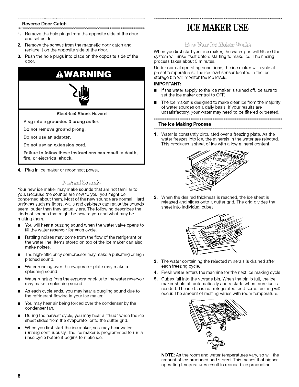
The Ice Making Process
1. Water is constantly circulated over a freezing plate. As the
water freezes into ice, the minerals in the water are rejected.
This produces a sheet of ice with a low mineral content.
4. Plug in ice maker or reconnect power.
Your new ice maker may make sounds that are not familiar to
you. Because the sounds are new to you, you might be
concerned about them. Most of the new sounds are normal. Hard
surfaces such as floors, walls and cabinets can make the sounds
seem louder than they actually are. The following describes the
kinds of sounds that might be new to you and what may be
making them.
• You will hear a buzzing sound when the water valve opens to
fill the water reservoir for each cycle.
• Rattling noises may come from the flow of the refrigerant or
the water line. Items stored on top of the ice maker can also
make noises.
• The high-efficiency compressor may make a pulsating or high
pitched sound.
• Water running over the evaporator plate may make a
splashing sound.
• Water running from the evaporator plate to the water reservoir
may make a splashing sound.
• As each cycle ends, you may hear a gurgling sound due to
the refrigerant flowing in your ice maker.
• You may hear air being forced over the condenser by the
condenser fan.
• During the harvest cycle, you may hear a "thud" when the ice
sheet slides from the evaporator onto the cutter grid.
• When you first start the ice maker, you may hear water
running continuously. The ice maker is programmed to run a
rinse cycle before it begins to make ice.
2. When the desired thickness is reached, the ice sheet is
released and slides onto a cutter grid. The grid divides the
sheet into individual cubes.
3. The water containing the rejected minerals is drained after
each freezing cycle.
4. Fresh water enters the machine for the next ice making cycle.
5. Cubes fall into the storage bin. When the bin is full, the ice
maker shuts off automatically and restarts when more ice is
needed. The ice bin is not refrigerated, and some melting will
occur. The amount of melting varies with room temperature.
NOTE: As the room and water temperatures vary, so will the
amount of ice produced and stored. This means that higher
operating temperatures result in reduced ice production.
1. To start the normal ice making cycle, select ON.
2. To stop ice maker operation, select OFR
® ® ® ®
ON/ OFF LOCKOUT SERVICE CLEANCYCLE
NOTE:
• Pressing the ON/OFF switch does not shut off power to
the ice maker.
• Allow 24 hours to produce the first batch of ice. Discard
the first batch produced.
Lock Out Mode
The control panel can be turned off for easy cleaning or to
prevent accidental activation by children or small pets.
NOTE: The lock feature does not shut off power to the ice maker
or to the ice maker bin light. It simply deactivates the control
panel.
1. To lock the control panel, press and hold the LOCKOUT
button until the indicator appears.
2. To unlock the control panel, press and hold the LOCKOUT
button until the indicator disappears.
Ice Maker System
Minerals that are removed from water during the freezing cycle
will eventually form a hard scaly deposit in the water system.
Cleaning the system regularly helps remove the mineral scale
buildup. How often you need to clean the system depends upon
how hard your water is. With hard water of 15 to 20 grains/gal.
(4 to 5 grains/liter), you may need to clean the system as often as
every 6 months.
NOTE: Use one 16 oz (473 mL) bottle of approved ice maker
cleaner. To order, call 1-800-442-9991 and ask for Part Number
4396808. In Canada, call 1-800-807-6777.
1. Turn off the ice maker.
2. Wait 5 to 10 minutes for the ice to fall into the storage bin.
Remove all ice from the storage bin.
3. Unscrew the drain cap from the bottom of the water pan
located inside the storage bin as shown. Allow the water to
drain completely.
4. Replace the drain cap securely on the water pan. If the drain
cap is loose, water will empty from the water pan and you will
have either thin ice or no ice.
5. Read and follow all handling information on the cleaner bottle
before completing the steps below. Use one 16 oz (473 mL)
bottle of approved ice maker cleaner.
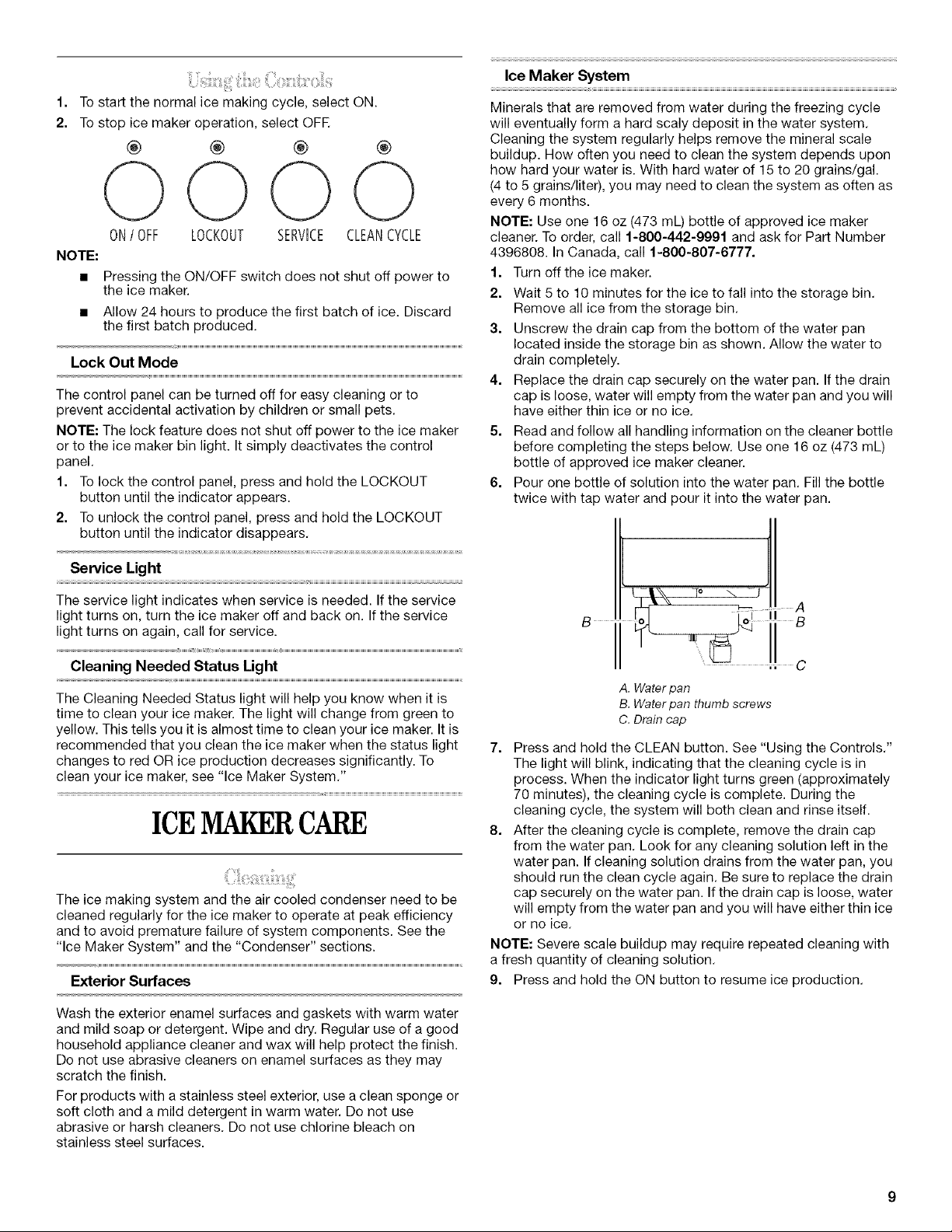
6. Pour one bottle of solution into the water pan. Fill the bottle
twice with tap water and pour it into the water pan.
Service Light
The service light indicates when service is needed. If the service
light turns on, turn the ice maker off and back on. If the service
light turns on again, call for service.
Cleaning Needed Status Light
The Cleaning Needed Status light will help you know when it is
time to clean your ice maker. The light will change from green to
yellow. This tells you it is almost time to clean your ice maker. It is
recommended that you clean the ice maker when the status light
changes to red OR ice production decreases significantly. To
clean your ice maker, see "Ice Maker System."
ICEMAKERCARE
The ice making system and the air cooled condenser need to be
cleaned regularly for the ice maker to operate at peak efficiency
and to avoid premature failure of system components. See the
"Ice Maker System" and the "Condenser" sections.
Exterior Surfaces
Wash the exterior enamel surfaces and gaskets with warm water
and mild soap or detergent. Wipe and dry. Regular use of a good
household appliance cleaner and wax will help protect the finish.
Do not use abrasive cleaners on enamel surfaces as they may
scratch the finish.
For products with a stainless steel exterior, use a clean sponge or
soft cloth and a mild detergent in warm water. Do not use
abrasive or harsh cleaners. Do not use chlorine bleach on
stainless steel surfaces.
B
!
A. Water pan
B. Water pan thumb screws
C. Drain cap
7. Press and hold the CLEAN button. See "Using the Controls."
The light will blink, indicating that the cleaning cycle is in
process. When the indicator light turns green (approximately
70 minutes), the cleaning cycle is complete. During the
cleaning cycle, the system will both clean and rinse itself.
8. After the cleaning cycle is complete, remove the drain cap
from the water pan. Look for any cleaning solution left in the
water pan. If cleaning solution drains from the water pan, you
should run the clean cycle again. Be sure to replace the drain
cap securely on the water pan. If the drain cap is loose, water
will empty from the water pan and you will have either thin ice
or no ice.
NOTE: Severe scale buildup may require repeated cleaning with
a fresh quantity of cleaning solution.
9. Press and hold the ON button to resume ice production.
 Loading...