

Whirlpool GI1500XHW5, GI1500XHW4, GI1500XHW3 Owner’s Manual
ICEMAKER
For questions about features, operation/performance
parts, accessories or service, call: 1-800-253-1301.
In Canada, call for assistance 1-800-461-5681, for installation
www.whirlpool.com or www.whirlpool.com/canada
and service, call: 1-800-807-6777
or visit our website at...
MACHINEA
GLA(_ONS
Au Canada, pour assistance, composez le 1-800-461-5681, pour
Table of Contents/Table des matieres ............. 2
installation ou service 1-800-807-6777
ou visitez notre site web h
www.whirlpool.c ore/ca nada
2217248
TABLEOFCONTENTS TABLEDESMATIERES
ICE MAKER SAFETY ...................................................................... 3
ICE MAKER INSTALLATION ......................................................... 4
Unpacking .................................................................................... 4
Location Requirements ................................................................ 4
Electrical Requirements ............................................................... 4
Leveling ........................................................................................ 5
Water Supply Connection ............................................................ 5
Reversing the Door Swing ........................................................... 7
Normal Sounds ............................................................................ 8
ICE MAKER USE ............................................................................ 9
How Your Ice Maker Works ......................................................... 9
Using the Controls ....................................................................... 9
ICE MAKER CARE .......................................................................... 9
Cleaning ........................................................................................ 9
Vacation and Moving Care ......................................................... 12
TROUBLESHOOTING .................................................................. 12
ASSISTANCE OR SERVICE ......................................................... 13
In the U.S.A ................................................................................ 13
In Canada ................................................................................... 13
WARRANTY .................................................................................. 14
SI_CURITI_ DE LA MACHINE A GLA(_ONS ................................ 15
INSTALLATION DE LA MACHINE .&GLA(_,ONS........................ 16
Deballage .................................................................................... 16
Emplacement d'installation ........................................................ 16
Specifications electriques .......................................................... 16
Nivellement ................................................................................. 17
Raccordement h I'alimentation en eau ...................................... 17
Inversion du sens d'ouverture de la porte ................................. 19
Sons normaux ............................................................................ 21
UTILISATION DE LA MACHINE .&GLA(_,ONS............................ 21
Fonctionnement de la machine a gla;ons ................................ 21
Utilisation des commandes ........................................................ 22
ENTRETIEN DE LA MACHINE .&GLA_ONS .............................. 22
Nettoyage ................................................................................... 22
Precautions h prendre pour les vacances
ou le dem6nagement .................................................................. 24
DI_PANNAGE ................................................................................. 25
ASSISTANCE OU SERVICE ......................................................... 26
Aux 12tats-Unis............................................................................ 26
Au Canada .................................................................................. 26
GARANTIE ..................................................................................... 27
Whi,l'l_oF
2
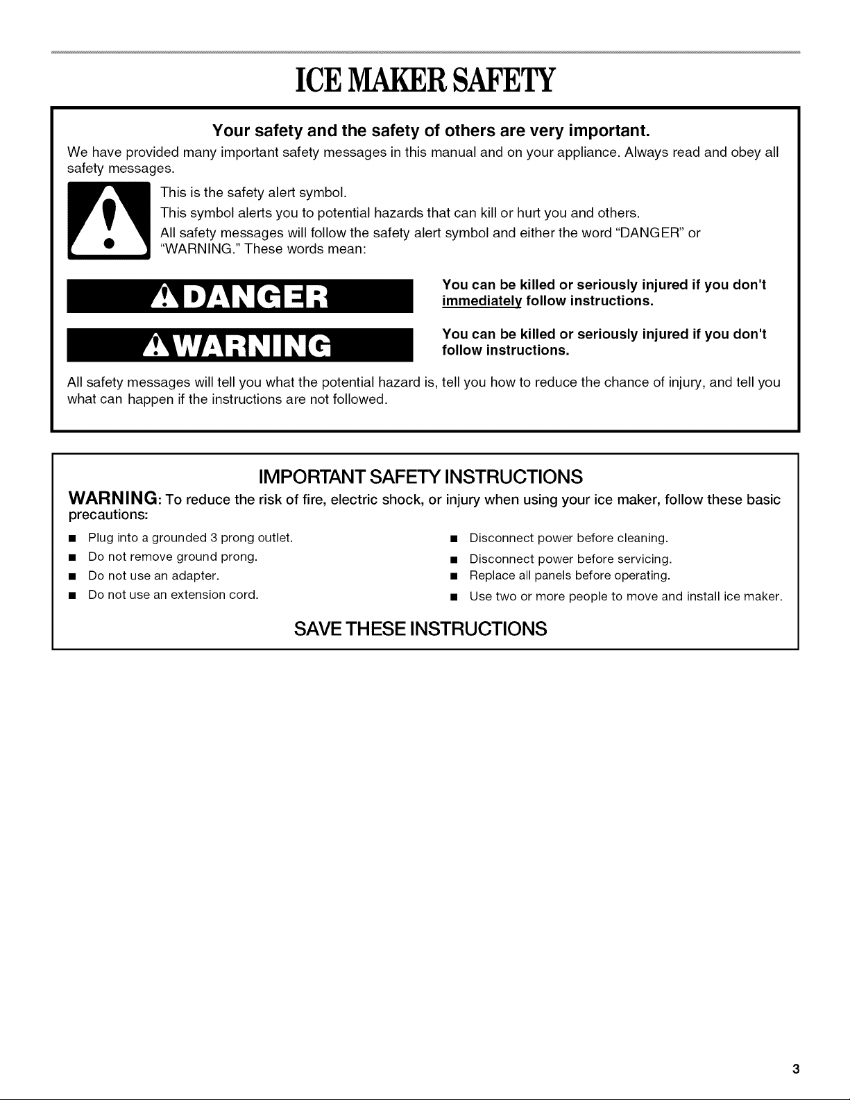
ICEMAKERSAFETY
Your safety and the safety of others are very important.
We have provided many important safety messages in this manual and on your appliance. Always read and obey all
safety messages.
This symbol alerts you to potential hazards that can kill or hurt you and others.
All safety messages will follow the safety alert symbol and either the word "DANGER" or
This is the safety alert symbol.
"WARNING." These words mean:
You can be killed or seriously injured if you don't
immediately follow instructions.
You can be killed or seriously injured if you don't
follow instructions.
All safety messages will tell you what the potential hazard is, tell you how to reduce the chance of injury, and tell you
what can happen if the instructions are not followed.
IMPORTANT SAFETY INSTRUCTIONS
WARNING: To reduce the risk of fire, electric shock, or injury when using your ice maker, follow these basic
precautions:
• Plug into a grounded 3 prong outlet.
• Do not remove ground prong.
• Do not use an adapter.
• Do not use an extension cord.
• Disconnect power before cleaning.
• Disconnect power before servicing.
• Replace all panels before operating.
• Use two or more people to move and install ice maker.
SAVE THESE INSTRUCTIONS
ICEMAKERINSTALLATION
Excessive Weight Hazard
Use two or more people to move and install
ice maker.
Failure to do so can result in back or other injury.
Removing packaging materials
Remove tape and glue from your ice maker before using.
• To remove any remaining tape or glue, rub the area briskly
with your thumb. Tape or glue residue can also be easily
removed by rubbing a small amount of liquid dish soap over
the adhesive with your fingers. Wipe with warm water and
dry.
• Do not use sharp instruments, rubbing alcohol, flammable
fluids, or abrasive cleaners to remove tape or glue. These
products can damage the surface of your ice maker.
Cleaning before use
After you remove all of the packaging materials, clean the inside
of your ice maker before using it. See the cleaning instructions in
the "Ice Maker Care" section.
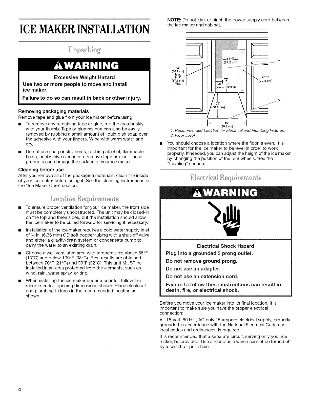
NOTE: Do not kink or pinch the power supply cord between
the ice maker and cabinet.
(29.2 cm)
34"
(86.4 cm)
Min,
341/2 '' 281/2"
(87.6 cm) "t- (72.4 cm)
Max. 9"
(8.9 cm)
24"
cm)
1
1. Recommended Location for Electrical and Plumbing Fixtures.
2. Floor Level
You should choose a location where the floor is even. It is
important for the ice maker to be level in order to work
properly. If needed, you can adjust the height of the ice maker
by changing the position of the rear wheels. See the
"Leveling" section.
(38.1 cm)
• To ensure proper ventilation for your ice maker, the front side
must be completely unobstructed. The unit may be closed-in
on the top and three sides, but the installation should allow
the ice maker to be pulled forward for servicing if necessary.
• Installation of the ice maker requires acold water supply inlet
of ¼ in. (6.35 mm) OD soft copper tubing with a shut-off valve
and either a gravity-drain system or condensate pump to
carry the water to an existing drain.
• Choose a well ventilated area with temperatures above 55°F
(13°C) and below 100°F (38°C). Best results are obtained
between 70°F (21°C) and 90°F (32°C). This unit MUST be
installed in an area protected from the elements, such as
wind, rain, water spray, or drip.
• When installing the ice maker under a counter, follow the
recommended opening dimensions shown. Place electrical
and plumbing fixtures in the recommended location as
shown.
Electrical Shock Hazard
Plug into a grounded 3 prong outlet.
Do not remove ground prong.
Do not use an adapter.
Do not use an extension cord.
Failure to follow these instructions can result in
death, fire, or electrical shock.
Before you move your ice maker into its final location, it is
important to make sure you have the proper electrical
connection:
A 115 Volt, 60 Hz., AC only 15 ampere electrical supply, properly
grounded in accordance with the National Electrical Code and
local codes and ordinances, is required.
It is recommended that a separate circuit, serving only your ice
maker, be provided. Use a receptacle which cannot be turned off
by a switch or pull chain.
4
Recommended grounding method
For your personal safety, this appliance must be grounded. This
appliance is equipped with a power supply cord having a 3 prong
grounding plug. To minimize possible shock hazard, the cord
must be plugged into a mating, 3 prong, grounding-type wall
receptacle, grounded in accordance with the National Electrical
Code and local codes and ordinances. If a mating wall receptacle
is not available, it is the personal responsibility of the customer to
have a properly grounded, 3 prong wall receptacle installed by a
qualified electrician.
It is important for the ice maker to be level in order to work
properly. Depending upon where you install the ice maker, you
may need to make several adjustments to level it.
Tools required
• Carpenter's level
• Adjustable wrench
• 1/4in. socket wrench
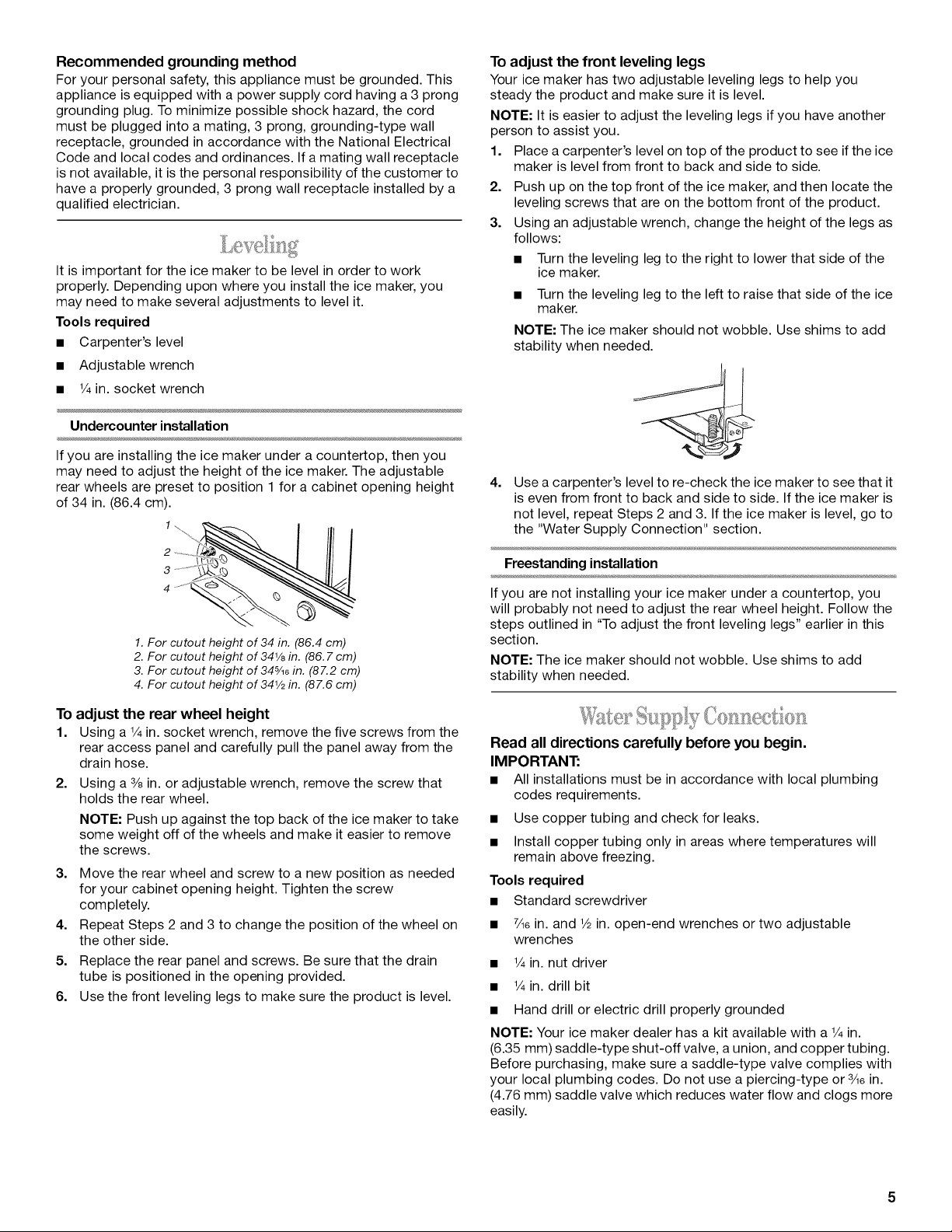
Undercounter installation
If you are installing the ice maker under a countertop, then you
may need to adjust the height of the ice maker. The adjustable
rear wheels are preset to position 1 for a cabinet opening height
of 34 in. (86.4 cm).
2
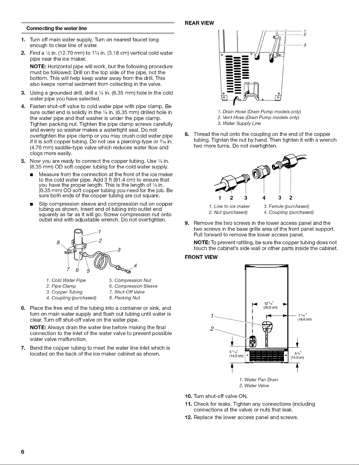
To adjust the front leveling legs
Your ice maker has two adjustable leveling legs to help you
steady the product and make sure it is level.
NOTE: It is easier to adjust the leveling legs if you have another
person to assist you.
1. Place a carpenter's level on top of the product to see if the ice
maker is level from front to back and side to side.
2. Push up on the top front of the ice maker, and then locate the
leveling screws that are on the bottom front of the product.
3. Using an adjustable wrench, change the height of the legs as
follows:
• Turn the leveling leg to the right to lower that side of the
ice maker.
• Turn the leveling leg to the left to raise that side of the ice
maker.
NOTE: The ice maker should not wobble. Use shims to add
stability when needed.
4.
Use a carpenter's level to re-check the ice maker to see that it
is even from front to back and side to side. Ifthe ice maker is
not level, repeat Steps 2 and 3. If the ice maker is level, go to
the "Water Supply Connection" section.
Freestanding installation
1.For cutout hoight of 34 in. (86.4 cm)
2. For cutout hoight of 341/8in. (86. 7 cm)
3. For cutout hoight of 34%8 in. (87.2 cm)
4. For cutout hoight of 341/2in. (87.6 cm)
To adjust the rear wheel height
1. Using a 1/4in. socket wrench, remove the five screws from the
rear access panel and carefully pull the panel away from the
drain hose.
2. Using a 3/8in. or adjustable wrench, remove the screw that
holds the rear wheel.
NOTE: Push up against the top back of the ice maker to take
some weight off of the wheels and make it easier to remove
the screws.
3. Move the rear wheel and screw to a new position as needed
for your cabinet opening height. Tighten the screw
completely.
4. Repeat Steps 2 and 3 to change the position of the wheel on
the other side.
5. Replace the rear panel and screws. Be sure that the drain
tube is positioned in the opening provided.
6. Use the front leveling legs to make sure the product is level.
If you are not installing your ice maker under a countertop, you
will probably not need to adjust the rear wheel height. Follow the
steps outlined in "To adjust the front leveling legs" earlier in this
section.
NOTE: The ice maker should not wobble. Use shims to add
stability when needed.
9" 7
Read all directions carefully before you begin.
IMPORTANT:
• All installations must be in accordance with local plumbing
codes requirements.
• Use copper tubing and check for leaks.
• Install copper tubing only in areas where temperatures will
remain above freezing.
Tools required
• Standard screwdriver
• 7Aein. and 1/2in. open-end wrenches or two adjustable
wrenches
• 1/4in. nut driver
• 1/4in. drill bit
• Hand drill or electric drill properly grounded
NOTE: Your ice maker dealer has a kit available with a 1/4in.
(6.35 mm) saddle-type shut-off valve, a union, and copper tubing.
Before purchasing, make sure a saddle-type valve complies with
your local plumbing codes. Do not use a piercing-type or 3Aein.
(4.76 mm) saddle valve which reduces water flow and clogs more
easily.
Connecting the water line
REAR VIEW
1. Turn off main water supply. Turn on nearest faucet long
enough to clear line of water.
2. Find a 1/2in. (12.70 mm) to 11/4in. (3.18 cm) vertical cold water
pipe near the ice maker.
NOTE: Horizontal pipe will work, but the following procedure
must be followed: Drill on the top side of the pipe, not the
bottom. This will help keep water away from the drill. This
also keeps normal sediment from collecting in the valve.
3. Using a grounded drill, drill a 1/4in. (6.35 mm) hole in the cold
water pipe you have selected.
4. Fasten shut-off valve to cold water pipe with pipe clamp. Be
sure outlet end is solidly in the 1/4in. (6.35 mm) drilled hole in
the water pipe and that washer is under the pipe clamp.
Tighten packing nut. Tighten the pipe clamp screws carefully
and evenly so washer makes a watertight seal. Do not
overtighten the pipe clamp or you may crush cold water pipe
if it is soft copper tubing. Do not use a piercing-type or 3/lein.
(4.76 mm) saddle-type valve which reduces water flow and
clogs more easily.
5. Now you are ready to connect the copper tubing. Use 1/4in.
(6.35 mm) OD soft copper tubing for the cold water supply.
• Measure from the connection at the front of the ice maker
to the cold water pipe. Add 3 ft (91.4 cm) to ensure that
you have the proper length. This is the length of 1/4in.
(6.35 mm) OD soft copper tubing you need for the job. Be
sure both ends of the copper tubing are cut square.
• Slip compression sleeve and compression nut on copper
tubing as shown. Insert end of tubing into outlet end
squarely as far as it will go. Screw compression nut onto
outlet end with adjustable wrench. Do not overtighten.
J ............... _,_,,_ 1
......................2
8. ..........3
/
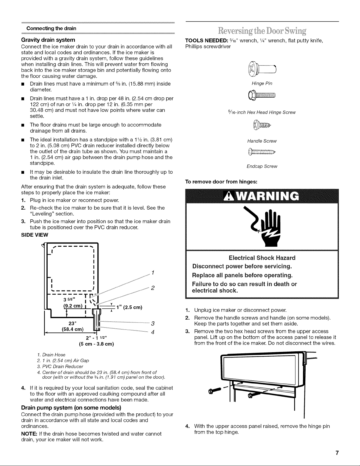
1.Drain Hose (Drain Pump models only)
2. Vent Hose (Drain Pump models only)
3. Water Supply Line
8.
Thread the nut onto the coupling on the end of the copper
tubing. Tighten the nut by hand. Then tighten it with a wrench
two more turns. Do not overtighten.
1 2 3 4 3 2
1.Line to ice maker
2. Nut (purchased)
g.
Remove the two screws in the lower access panel and the
two screws in the base grille area of the front panel support.
Pull forward to remove the lower access panel.
NOTE: To prevent rattling, be sure the copper tubing does not
touch the cabinet's side wall or other parts inside the cabinet.
FRONT VIEW
3. Ferrule (purchased)
4. Coupling (purchased)
1. Cold Water Pipe
2. Pipe Clamp
3. Copper Tubing
4. Coupfing (purchased)
6.
Place the free end of the tubing into a container or sink, and
5. Compression Nut
6. Compression Sleeve
7. Shut-Off Valve
8. Packing Nut
turn on main water supply and flush out tubing until water is
clear. Turn off shut-off valve on the water pipe.
NOTE: Always drain the water line before making the final
connection to the inlet of the water valve to prevent possible
water valve malfunction.
7=
Bend the copper tubing to meet the water line inlet which is
located on the back of the ice maker cabinet as shown.
5%"
(14.3 cm)
1. Water Pan Drain
2. Water Valve
10. Turn shut-off valve ON.
11. Check for leaks. Tighten any connections (including
connections at the valve) or nuts that leak.
12. Replace the lower access panel and screws.
6
Connecting the drain
Gravity drain system
Connect the ice maker drain to your drain in accordance with all
state and local codes and ordinances. If the ice maker is
provided with a gravity drain system, follow these guidelines
when installing drain lines. This will prevent water from flowing
back into the ice maker storage bin and potentially flowing onto
the floor causing water damage.
• Drain lines must have a minimum of 5/8in. (15.88 mm) inside
diameter.
Drain lines must have a 1 in. drop per 48 in. (2.54 cm drop per
122 cm) of run or 1/4in. drop per 12 in. (6.35 mm per
30.48 cm) and must not have low points where water can
settle.
• The floor drains must be large enough to accommodate
drainage from all drains.
• The ideal installation has a standpipe with a 1V2in. (3.81 cm)
to 2 in. (5.08 cm) PVC drain reducer installed directly below
the outlet of the drain tube as shown. You must maintain a
1 in. (2.54 cm) air gap between the drain pump hose and the
standpipe.
• It may be desirable to insulate the drain line thoroughly up to
the drain inlet.
After ensuring that the drain system is adequate, follow these
steps to properly place the ice maker:
1. Plug in ice maker or reconnect power.
2. Re-check the ice maker to be sure that it is level. See the
"Leveling" section.
3. Push the ice maker into position so that the ice maker drain
tube is positioned over the PVC drain reducer.
SIDE VIEW
TOOLS NEEDED: 5/le"wrench, 1/4"wrench, flat putty knife,
Phillips screwdriver
Hinge Pin
5/16-inchHex Head Hinge Screw
Handle Screw
Endcap Screw
To remove door from hinges:
1
2
T
35/8" I
3
4
1. Drain Hose
2. 1 in. (2.54 cm) Air Gap
3. PVC Drain Reducer
4. Center of drain should be 23 in. (58.4 cm) from front of
door (with or without the 3/4in. (1.91 cm) panel on the door).
4. If it is required by your local sanitation code, seal the cabinet
to the floor with an approved caulking compound after all
water and electrical connections have been made.
Drain pump system (on some models)
Connect the drain pump hose (provided with the product) to your
drain in accordance with all state and local codes and
ordinances.
NOTE: If the drain hose becomes twisted and water cannot
drain, your ice maker will not work.
Electrical Shock Hazard
Disconnect power before servicing.
Replace a(( panels before operating.
Failure to do so can result in death or
electrical shock.
1.
Unplug ice maker or disconnect power.
2.
Remove the handle screws and handle (on some models).
Keep the parts together and set them aside.
3.
Remove the two hex head screws from the upper access
panel. Lift up on the bottom of the access panel to release it
from the front of the ice maker. Do not disconnect the wires.
U
4. With the upper access panel raised, remove the hinge pin
from the top hinge.
5. Removethedoorfromthehingesandscrewthetophingepin
backintothetophinge.
6. Replacetheupperaccesspanellooselyontheicemaker.
7. Reversethedoorendcapsasfollows:
• Removeboththescrewsandendcaps(topandbottom).
• Placethetopendcaponthebottomoftheoppositeside
ofthedoorwiththelongflatsidefacingthedoorfront.
• Placethebottomendcaponthetopoftheoppositeside
ofthedoorwiththelongflatsidefacingthedoorfront.
8. Setthedooraside.
To reverse the hinges:
1. Unscrew and remove the top hinge. Replace the screws in
the empty hinge holes.
2. Remove the screws from the bottom of the opposite side of
the ice maker cabinet. Turn the top hinge upside down so that
the hinge pin points up. Place the hinge on the bottom
opposite side of the ice maker and tighten screws.
3. Remove the plastic hinge pin sleeve from the "old" bottom
hinge and replace it on the new bottom hinge pin.
4. Remove the "old" bottom hinge screws and hinge. Replace
the screws in the empty hinge holes.
5. Remove the screws from the top of the opposite side of the
ice maker cabinet. Turn the hinge upside down so that the
hinge pin points down.
6. Raise the upper access panel and place the hinge on the top
opposite side of the ice maker. Tighten the hinge screws.
7. Remove the top hinge pin.
To replace door on hinges:
1. Place plastic hinge pin sleeve in the top hinge hole on the
door. Align the door with the top hinge hole and replace the
top hinge pin.
2. Replace the upper access panel and secure it with the hex
head screws.
3. Replace the handle and handle screws.
Top Hinge
1
I
2
3
1. Hinge Pin
2. Hinge Pin Sleeve
3. Hinge
4. Flex Head Hinge Screw
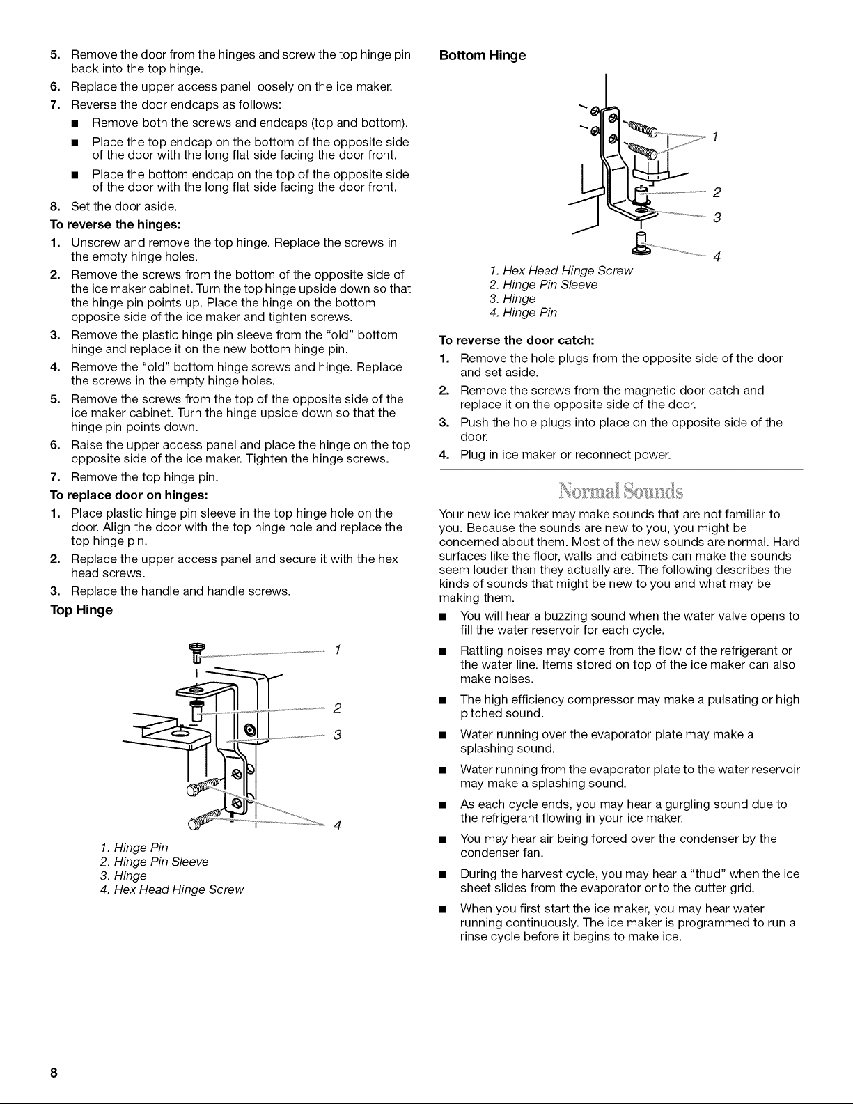
Bottom Hinge
2
3
J
4
1. Hex Head Hinge Screw
2. Hinge Pin Sleeve
3. Hinge
4. Hinge Pin
To reverse the door catch:
1. Remove the hole plugs from the opposite side of the door
and set aside.
2. Remove the screws from the magnetic door catch and
replace it on the opposite side of the door.
3. Push the hole plugs into place on the opposite side of the
door.
4. Plug in ice maker or reconnect power.
Your new ice maker may make sounds that are not familiar to
you. Because the sounds are new to you, you might be
concerned about them. Most of the new sounds are normal. Hard
surfaces like the floor, walls and cabinets can make the sounds
seem louder than they actually are. The following describes the
kinds of sounds that might be new to you and what may be
making them.
• You will hear a buzzing sound when the water valve opens to
fill the water reservoir for each cycle.
• Rattling noises may come from the flow of the refrigerant or
the water line. Items stored on top of the ice maker can also
make noises.
• The high efficiency compressor may make a pulsating or high
pitched sound.
• Water running over the evaporator plate may make a
splashing sound.
• Water running from the evaporator plate to the water reservoir
may make a splashing sound.
• As each cycle ends, you may hear a gurgling sound due to
the refrigerant flowing in your ice maker.
• You may hear air being forced over the condenser by the
condenser fan.
• During the harvest cycle, you may hear a "thud" when the ice
sheet slides from the evaporator onto the cutter grid.
• When you first start the ice maker, you may hear water
running continuously. The ice maker is programmed to run a
rinse cycle before it begins to make ice.
8
ICEMAKERUSE
When you first start your ice maker, the water pan will fill and the
system will rinse itself before starting to make ice. The rinsing
process takes about five minutes.
Under normal operating conditions, the ice maker will cycle at
preset temperatures. The ice level sensor located in the ice
storage bin will monitor the ice levels.
IMPORTANT:
• If the water supply to the ice maker is turned off, be sure to
set the ice maker control to OFF.
• The ice maker is designed to make clear ice from the majority
of water sources on a daily basis. If your results are
unsatisfactory, your water may need to be filtered or treated.
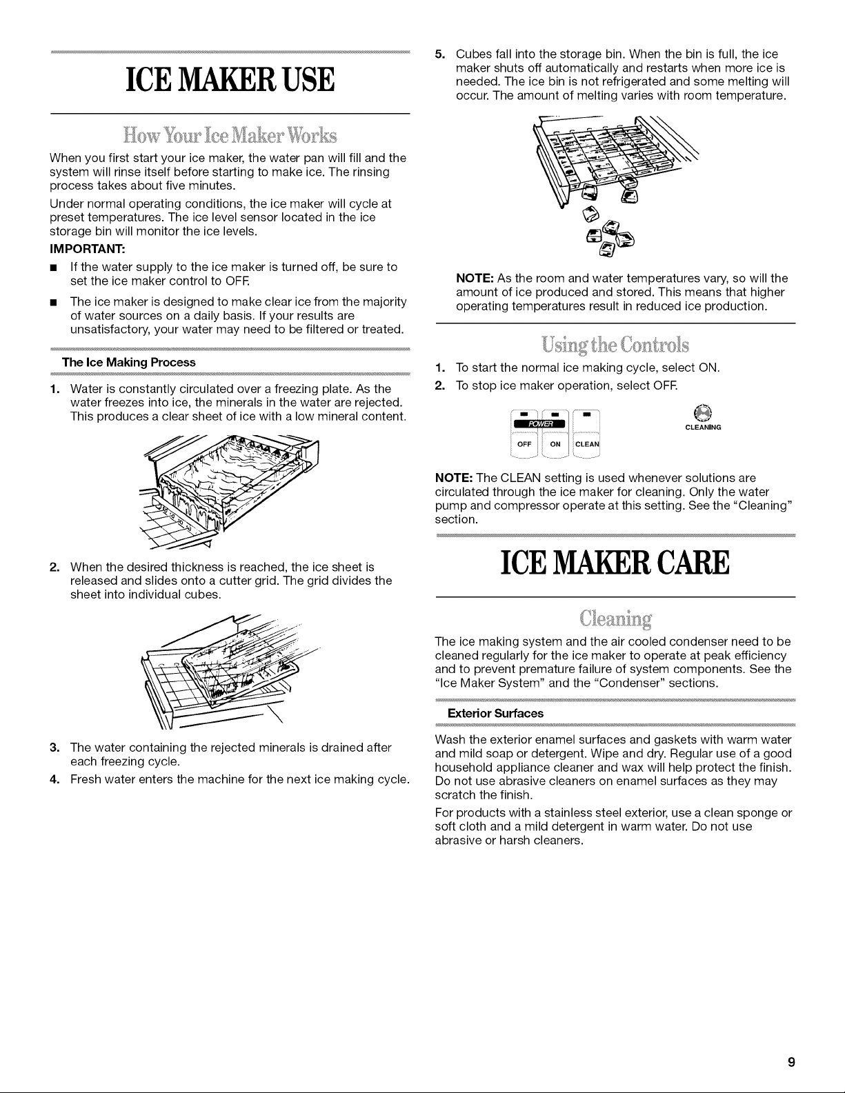
5=
Cubes fall into the storage bin. When the bin is full, the ice
maker shuts off automatically and restarts when more ice is
needed. The ice bin is not refrigerated and some melting will
occur. The amount of melting varies with room temperature.
NOTE: As the room and water temperatures vary, so will the
amount of ice produced and stored. This means that higher
operating temperatures result in reduced ice production.
W'_ _ ° ' . 'X =, I
The Ice Making Process
1.
Water is constantly circulated over afreezing plate. As the
water freezes into ice, the minerals in the water are rejected.
This produces a clear sheet of ice with a low mineral content.
2.
When the desired thickness is reached, the ice sheet is
released and slides onto a cutter grid. The grid divides the
sheet into individual cubes.
3. The water containing the rejected minerals is drained after
each freezing cycle.
4. Fresh water enters the machine for the next ice making cycle.
1=
To start the normal ice making cycle, select ON.
2.
To stop ice maker operation, select OFF.
CLEANING
iCLEAN(
NOTE: The CLEAN setting is used whenever solutions are
circulated through the ice maker for cleaning. Only the water
pump and compressor operate at this setting. See the "Cleaning"
section.
ICEMAKERCARE
The ice making system and the air cooled condenser need to be
cleaned regularly for the ice maker to operate at peak efficiency
and to prevent premature failure of system components. See the
"Ice Maker System" and the "Condenser" sections.
Exterior Surfaces
Wash the exterior enamel surfaces and gaskets with warm water
and mild soap or detergent. Wipe and dry. Regular use of a good
household appliance cleaner and wax will help protect the finish.
Do not use abrasive cleaners on enamel surfaces as they may
scratch the finish.
For products with a stainless steel exterior, use a clean sponge or
soft cloth and a mild detergent in warm water. Do not use
abrasive or harsh cleaners.
 Loading...