

Whirlpool GH7208XRS4, GH7208XRQ4, GH7208XRB4 Installation Guide
MICROWAVE HOOD COMBINATION
INSTALLATION INSTRUCTIONS
This product is suitable for use above electric or gas cooking products up to 36" (91.4 cm) wide.
These installation instructions cover different models. The appearance of your particular model may differ slightly from the
illustration in these installation instructions.
Table of Contents
MICROWAVEHOOD COMBINATION SAFETY..............................1
INSTALLATIONREQUIREMENTS...................................................2
Toolsand Parts...............................................................................2
Location Requirements...................................................................2
Product Dimensions.......................................................................3
ElectricalRequirements..................................................................3
INSTALLATION INSTRUCTIONS.....................................................4
Remove Mounting Plate.................................................................4
Convert Microwave Ovento ExternalVenting...............................4
Locate Wall Stud(s).........................................................................6
Mark RearWall................................................................................7
Drill Holesin RearWall....................................................................7
Attach Mounting Plate to Wall........................................................8
PrepareUpper Cabinet...................................................................8
Installthe Microwave Oven ............................................................9
Install Filters..................................................................................10
Complete Installation....................................................................10
VENTINGDESIGNSPECIFICATIONS............................................11
ASSISTANCE...................................................................................12
Replacement Parts .......................................................................12
Accessories...................................................................................12
MICROWAVE HOOD COMBINATION SAFETY
Your safety and the safety of others are very important.
We have provided many important safety messages in this manual and on your appliance. Always read and obey all safety
messages.
This is the safety alert symbol.
This symbol alerts you to potential hazards that can kill or hurt you and others.
All safety messages will follow the safety alert symbol and either the word "DANGER" or "WARNING."
These words mean:
You can be killed or seriously injured if you don't immediately
follow instructions.
You can be killed or seriously injured if you don't follow
instructions.
All safety messages will tell you what the potential hazard is, tell you how to reduce the chance of injury, and tell you what can
happen if the instructions are not followed.
W10502371A
INSTALLATION REQUIREMENTS
The microwave oven is set for recirculation installation. For external (wall or roof) venting, see "Venting Design Specifications" section.
.... and Parts
Tools Needed
Gather the required tools and parts before starting installation.
Read and follow the instructions provided with any tools
listed here.
• Measuring tape • Stud finder
• Pencil • 7/16" socket wrench
• Masking tape or thumbtacks (or box wrench) for 1/4" x
• Scissors 2" lag screws
• T10 TORX®tscrewdriver • 11/2"(3.8 cm) diam. hole
• No. 3 Phillips screwdriver for cabinet
1/4-20 x 3" bolts
• Drill
• 3/16" (5 mm) and 3/8" weatherproof caulking
(10 mm) drill bits compound
• 3/4" (19 mm) hole saw • Duct tape
• Diagonal cutting pliers
Materials Needed
• Standard fittings for wall or roof venting. See "Venting Design
Specifications" section.
Parts Supplied
For information on reordering, see "Replacement Parts" section.
NOTE: The hardware items listed here are for wood studs. For
other types of wall structures, be sure to use appropriate
fasteners.
A
drill bit for wood or metal
• Keyhole saw
• Caulking gun and
Location Requirements
Check the opening where the microwave oven will be installed.
The location must provide:
• Minimum installation dimensions. See "Installation
Dimensions" illustration.
• Minimum one 2" x 4" (50.8 x 101.6 mm) wood wall stud and
minimum 3/8" (10 mm) thickness drywall or plaster/lath within
cabinet opening.
• Support for weight of 150 Ibs (68 kg), which includes
microwave oven and items placed inside the microwave oven
and upper cabinet.
• Grounded electrical outlet inside upper cabinet. See
"Electrical Requirements" section.
NOTES:
If installing the microwave oven near a left sidewall, make
sure there is at least 3" (7.6 cm) of clearance between the wall
and the microwave oven, so that the door can open fully.
Some cabinet and building materials are not designed to
withstand the heat produced by the microwave oven for
cooking. Check with your builder or cabinet supplier to make
sure that the materials used will not discolor, delaminate or
sustain other damages.
Special Requirements
For Wall Venting Installation Only:
• Cutout must be free of any obstructions so that the vent fits
properly, and the damper blade opens freely and fully.
For Roof Venting Installation Only:
• If you are using a rectangular to round transition piece,
3" (7.6 cm) clearance needs to exist above the microwave
oven so that the damper blade can open freely and fully. See
"Rectangular to Round Transition" illustration in "Venting
Design Specifications" section.
H
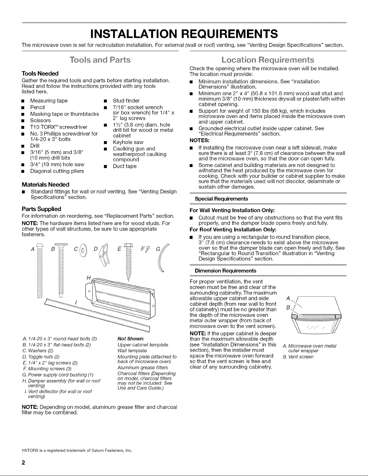
A. 1/4-20 x 3" round-head bolts (2)
B. 1/4-20 x 3" flat-head bolts (2)
C. Washers (2)
D. Toggle nuts (2)
E. 1/4" x 2" lag screws (2)
F. Mounting screws (3)
G. Power supply cord bushing (1)
H. Damper assembly (for wall or roof
venting)
I. Vent deflector (for wall or roof
venting)
Not Shown:
Upper cabinet template
Wall template
Mounting plate (attached to
back of microwave oven)
Aluminum grease filters
Charcoal filters (Depending
on model, charcoal filters
may not be included. See
Use and Care Guide.)
NOTE: Depending on model, aluminum grease filter and charcoal
filter may be combined.
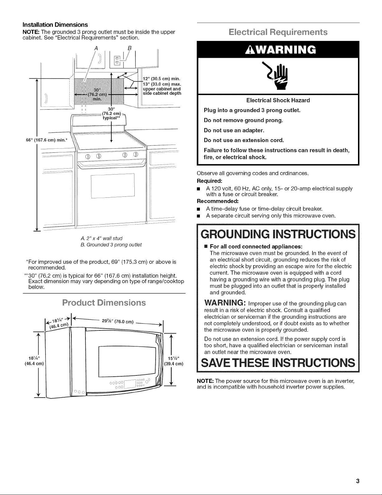
Dimension Requirements
For proper ventilation, the vent
screen must be free and clear of the
surrounding cabinetry. The maximum
allowable upper cabinet and side
cabinet depth (from rear wall to front
of cabinetry) must be no greater than
the depth of the microwave oven
metal outer wrapper (from back of
microwave oven to the vent screen).
NOTE: If the upper cabinet is deeper
than the maximum allowable depth
(see "Installation Dimensions" in this
section), then the installer must
space the microwave oven forward
so that the vent screen is free and
clear of any surrounding cabinetry.
A. Microwave oven metal
outer wrapper
B. Vent screen
1-®TORX is a registered trademark of Saturn Fasteners, Inc.
2
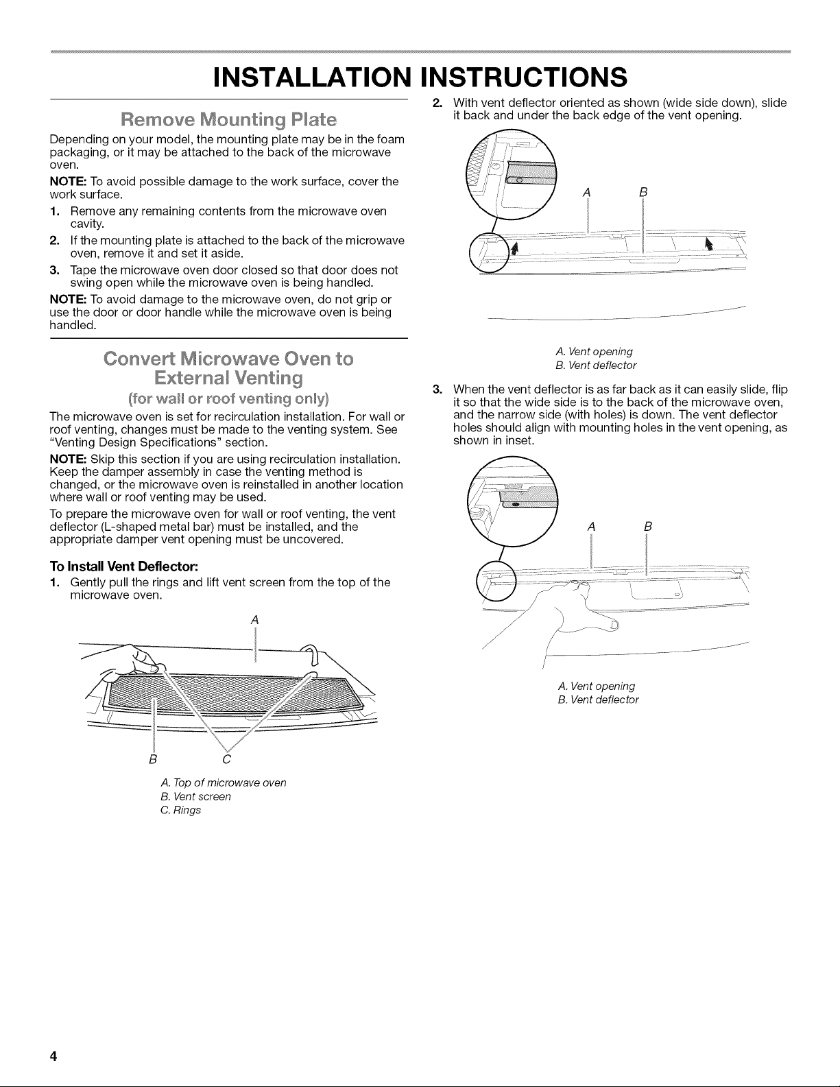
Installation Dimensions
NOTE: The grounded 3 prong outlet must be inside the upper
cabinet. See "Electrical Requirements" section.
A B
12" (30.5 cra) rain.
'13" (33.0 cm) max.
upper cabinet and
side cabinet depth
ii...................
Electrical Requirements
Electrical Shock Hazard
Plug into a grounded 3 prong outlet.
Do not remove ground prong.
Do not use an adapter.
Do not use an extension cord.
Falure to folow these instructions can result in death,
fire, or electrical shock.
Observe all governing codes and ordinances.
Required:
[] A 120 volt, 60 Hz, AC only, 15- or 20-amp electrical supply
with a fuse or circuit breaker.
Recommended:
[] A time-delay fuse or time-delay circuit breaker.
[] A separate circuit serving only this microwave oven.
A. 2" x 4" wall stud
B. Grounded 3 prong outlet
*For improved use of the product, 69" (175.3 cm) or above is
recommended.
**30" (76.2 cm)is typical for 66" (167.6 cm)installation height.
Exact dimension may vary depending on type of range/cooktop
below.
Product Dimensions
T
18Y4"
(46.4 era)
T
151/2''
(39.4 era)
l
!
GROUNDING iNSTRUCTiONS
[] For all cord connected appliances:
The microwave oven must be grounded. In the event of
an electrical short circuit, grounding reduces the risk of
electric shock by providing an escape wire for the electric
current. The microwave oven is equipped with a cord
having a grounding wire with a grounding plug. The plug
must be plugged into an outlet that is properly installed
and grounded.
WARNING: Improper use of the grounding plug can
result in a risk of electric shock. Consult a qualified
electrician or serviceman if the grounding instructions are
not completely understood, or if doubt exists as to whether
the microwave oven is properly grounded.
Do not use an extension cord. If the power supply cord is
too short, have a qualified electrician or serviceman install
an outlet near the microwave oven.
SAVE THESE iNSTRUCTiONS
NOTE: The power source for this microwave oven is an inverter,
and is incompatible with household inverter power supplies.
INSTALLATION INSTRUCTIONS
Remove Mounting P ate
Depending on your model, the mounting plate may be in the foam
packaging, or it may be attached to the back of the microwave
oven.
NOTE: To avoid possible damage to the work surface, cover the
work surface.
1. Remove any remaining contents from the microwave oven
cavity.
2. If the mounting plate is attached to the back of the microwave
oven, remove it and set it aside.
3. Tape the microwave oven door closed so that door does not
swing open while the microwave oven is being handled.
NOTE: To avoid damage to the microwave oven, do not grip or
use the door or door handle while the microwave oven is being
handled.
2. With vent deflector oriented as shown (wide side down), slide
it back and under the back edge of the vent opening.
ConveA Microwave Oven to
Extema Venting
(for wall or Iroof ventiiing on_y}
The microwave oven is set for recirculation installation. For wall or
roof venting, changes must be made to the venting system. See
"Venting Design Specifications" section.
NOTE: Skip this section if you are using recirculation installation.
Keep the damper assembly in case the venting method is
changed, or the microwave oven is reinstalled in another location
where wall or roof venting may be used.
To prepare the microwave oven for wall or roof venting, the vent
deflector (L-shaped metal bar) must be installed, and the
appropriate damper vent opening must be uncovered.
To Install Vent Deflector:
1. Gently pull the rings and lift vent screen from the top of the
microwave oven.
A. Vent opening
B. Vent deflector
3=
When the vent deflector is as far back as it can easily slide, flip
it so that the wide side is to the back of the microwave oven,
and the narrow side (with holes) is down. The vent deflector
holes should align with mounting holes in the vent opening, as
shown in inset.
A. Vent opening
B. Vent deflector
B C
A. Top of microwave oven
B. Vent screen
C. Rings
 Loading...