

Whirlpool GGW9260 User Manual
®
®
ELECTRONIC
GAS DRYER
Use & Care Guide
In the U.S.A., for questions about features, operation/performance,
Tab l e o f C o n t e n t s .................................................... 2
parts, accessories or service call:
or visit our website at... www.whirlpool.com
1-800-253-1301
8530063
Model GGW9260

TABLE OF CONTENTS
DRYER SAFETY..............................................................................3
INSTALLATION INSTRUCTIONS..................................................5
Tools and Parts ............................................................................5
Options.........................................................................................5
Location Requirements ...............................................................6
Electrical Requirements ...............................................................7
Gas Supply Requirements...........................................................8
Venting Requirements..................................................................9
Plan Vent System.......................................................................10
Install Vent System.....................................................................11
Install Leveling Legs...................................................................12
Level Dryer .................................................................................12
Make Gas Connection ...............................................................12
Connect Vent..............................................................................13
Complete Installation .................................................................13
DRYER USE ..................................................................................14
Starting Your Dryer.....................................................................14
Stopping Your Dryer ..................................................................15
Pausing or Restarting.................................................................15
Control Locked...........................................................................15
Loading.......................................................................................15
Drying and Cycle Tips ................................................................16
Status Lights...............................................................................16
Cycles.........................................................................................17
Additional Features ....................................................................18
Drying Rack ................................................................................18
DRYER CARE................................................................................19
Cleaning the Dryer Location.......................................................19
Cleaning the Lint Screen............................................................19
Cleaning the Dryer Interior .........................................................20
Removing Accumulated Lint......................................................20
Vacation and Moving Care.........................................................20
Changing the Drum Light ...........................................................20
TROUBLESHOOTING ..................................................................21
ASSISTANCE OR SERVICE.........................................................22
WARRANTY ..................................................................................24
2
DRYER SAFETY
Your safety and the safety of others are very important.
We have provided many important safety messages in this manual and on your appliance. Always read and obey all safety
messages.
This is the safety alert symbol.
This symbol alerts you to potential hazards that can kill or hurt you and others.
All safety messages will follow the safety alert symbol and either the word “DANGER” or “WARNING.”
These words mean:
You can be killed or seriously injured if you don't immediately
DANGER
WARNING
All safety messages will tell you what the potential hazard is, tell you how to reduce the chance of injury, and tell you what can
happen if the instructions are not followed.
WARNING: For your safety, the information in this manual must be followed to minimize
the risk of fire or explosion, or to prevent property damage, personal injury, or death.
follow instructions.
can be killed or seriously injured if you don't
You
instructions.
follow
– Do not store or use gasoline or other flammable vapors and liquids in the vicinity of this
or any other appliance.
– WHAT TO DO IF YOU SMELL GAS:
Do not try to light any appliance.
•
Do not touch any electrical switch; do not use any phone in your building.
•
Clear the room, building, or area of all occupants.
•
Immediately call your gas supplier from a neighbor's phone. Follow the gas supplier's
•
instructions.
If you cannot reach your gas supplier, call the fire department.
•
– Installation and service must be performed by a qualified installer, service agency, or
the gas supplier.
In the State of Massachusetts, the following installation instructions apply:
■ Installations and repairs must be performed by a qualified or licensed contractor, plumber, or gasfitter qualified or licensed by
the State of Massachusetts.
■ If using a ball valve, it shall be a T-handle type.
■ A flexible gas connector, when used, must not exceed 3 feet.
3

IMPORTANT SAFETY INSTRUCTIONS
WARNING:
including the following:
■
Read all instructions before using the dryer.
■
Do not place items exposed to cooking oils in your dryer.
Items contaminated with cooking oils may contribute to
a chemical reaction that could cause a load to catch fire.
■
Do not dry articles that have been previously cleaned in,
washed in, soaked in, or spotted with gasoline, drycleaning solvents, other flammable, or explosive
substances as they give off vapors that could ignite or
explode.
■
Do not allow children to play on or in the dryer. Close
supervision of children is necessary when the dryer is
used near children.
■
Before the dryer is removed from service or discarded,
remove the door to the drying compartment.
■
Do not reach into the dryer if the drum is moving.
■
Do not install or store the dryer where it will be exposed
to the weather.
■
Do not tamper with controls.
To reduce the risk of fire, electric shock, or injury to persons when using the dryer, follow basic precautions,
SAVE THESE INSTRUCTIONS
■
Do not repair or replace any part of the dryer or attempt
any servicing unless specifically recommended in this
Use and Care Guide or in published user-repair
instructions that you understand and have the skills to
carry out.
■
Do not use fabric softeners or products to eliminate static
unless recommended by the manufacturer of the fabric
softener or product.
■
Do not use heat to dry articles containing foam rubber or
similarly textured rubber-like materials.
■
Clean lint screen before or after each load.
■
Keep area around the exhaust opening and adjacent
surrounding areas free from the accumulation of lint, dust,
and dirt.
■
The interior of the dryer and exhaust vent should be
cleaned periodically by qualified service personnel.
■
See installation instructions for grounding requirements.
IMPORTANT: The gas installation must conform with local codes, or in the absence of local codes, with the National Fuel Gas
Code, ANSI Z223.1/NFPA 54.
The dryer must be electrically grounded in accordance with local codes, or in the absence of local codes, with the National
Electrical Code, ANSI/NFPA 70.
4
INSTALLATION INSTRUCTIONS
Tool s and Parts
Check that you have everything necessary for correct installation.
Proper installation is your responsibility.
■ 8" or 10" pipe wrench
■ 8" or 10" adjustable
wrench (for gas
connections)
■ Flat-blade screwdriver
■ Adjustable wrench that
opens to 1" (2.5 cm) or
hex-head socket wrench
(for adjusting dryer feet)
■ Level
■ ¹⁄₄" nut driver or socket
wrench
Parts supplied
Remove parts packages from dryer drum. Check that all parts are
included.
■ Parts package.
4 Leveling legs
NOTE: Do not use leveling legs if installing the dryer on a
pedestal.
Parts needed
Check local codes and with gas supplier. Check existing gas
supply, electrical supply and venting. Read “Electrical
Requirements,” “Gas Supply Requirements” and “Ve nting
Requirements” before purchasing parts.
■ For close-clearance installations between 31.5" (80.01 cm)
and 37" (93.98 cm), see “Plan Vent System” section for
venting requirements.
■ Knife
■ Safety glasses
■ Vent clamps
■ Pipe-joint compound
resistant to L.P. gas
■ Caulking gun and
compound (for installing
new exhaust vent)
■ Gloves
■ Pliers
Options
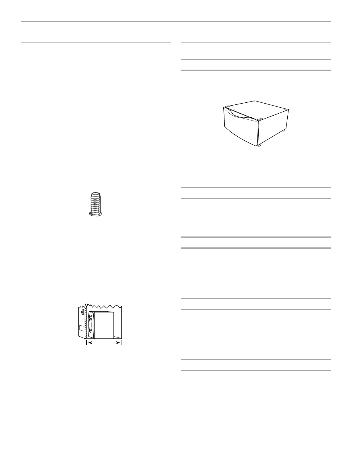
Pedestal
Are you placing the dryer on a pedestal? You may purchase a
pedestal separately for this dryer. This pedestal will add about
13" (33 cm) to the height of your unit for a total height of
approximately 51" (130 cm).
Optional pedestal
To order, call the dealer from whom you purchased your dryer or
refer to the “Assistance or Service” section of this manual. Ask
for Part Number LAB2700MQ (White), LAB2700MT (Biscuit) or
LAB2700ML (Pewter).
Stack Kit
Are you planning to stack your DUET® washer and dryer? To do
so, you will need to purchase a Stack Kit.
To order, call the dealer from whom you purchased your dryer or
refer to the “Assistance or Service” section of this manual. Ask
for Part Number 8541503.
Door Reversal Kit
Are you planning to reverse the door swing direction on your
DUET® dryer? To do so, you will need to purchase a Door
Reversal Kit.
To order, call the dealer from whom you purchased your dryer or
refer to the “Assistance or Service” section of this manual. Ask
for Part Number 8530069 (Shield Blue), 8530070 (Shield
Platinum), 8530071 (Biscuit) or 8530072 (Pewter).
37"
(93.98 cm)
Mobile home installations require special parts (listed following)
that may be ordered by calling the dealer from whom you
purchased your dryer. For further information, please refer to the
“Assistance or Service” section of this manual.
■ Mobile Home Installation Kit. Ask for Part Number 346764.
■ Metal exhaust system hardware.
Door Reversal and Stack Combination Kit
Are you planning to reverse the door swing direction on your
®
dryer and stack your DUET® washer and dryer? To do so,
DUET
you can purchase a Door Reversal and Stack Combination Kit.
To order, call the dealer from whom you purchased your dryer or
refer to the “Assistance and Service” section of this manual. Ask
for Part Number 8530073 (Shield Blue), 8530074 (Shield
Platinum), 8530075 (Biscuit) or 8530076 (Pewter).
Backguard
If you are installing your DUET® washer and dryer and wish to
avoid having loose items fall behind your machines, you may
purchase a pair of washer/dryer backguards. These will reduce
the chance of items falling behind the machines during operation.
To order, call the dealer from whom you purchased your dryer or
refer to the “Assistance or Service” section of this manual. Ask
for Part Number 8558694 (White), 8558695 (Biscuit) or 8558696
(Pewter).
5
Location Requirements
WARNING
Explosion Hazard
Keep flammable materials and vapors, such as
gasoline, away from dryer.
Place dryer at least 18 inches (46 cm) above the floor
for a garage installation.
Failure to do so can result in death, explosion, or fire.
You will need
■ A location that allows for proper exhaust installation. A gas
dryer must be exhausted to the outdoors. See “Venting
Requirements.”
■ A grounded electrical outlet located within 2 ft (61 cm) of
either side of the dryer. See “Electrical Requirements.”
■ A sturdy floor to support the total dryer weight of 200 lbs
(90.7 kg). The combined weight of a companion appliance
should also be considered.
■ A level floor with a maximum slope of 1" (2.5 cm) under entire
dryer. If slope is greater than 1" (2.5 cm), install Extended
Dryer Feet Kit, Part Number 279810. Clothes may not tumble
properly and automatic sensor cycles may not operate
correctly if dryer is not level.
■ For a garage installation, you will need to place the dryer at
least 18" (46 cm) above the floor. If using a pedestal, you will
need an additional 6" (15.24 cm).
Do not operate your dryer at temperatures below 45ºF (7ºC). At
lower temperatures, the dryer might not shut off at the end of an
automatic cycle. This can result in longer drying times.
The dryer must not be installed or stored in an area where it will
be exposed to water and/or weather.
Check code requirements. Some codes limit, or do not permit,
installation of the dryer in garages, closets, mobile homes, or
sleeping quarters. Contact your local building inspector.
NOTE: No other fuel-burning appliance can be installed in the
same closet as a dryer.
Installation clearances
■ The location must be large enough to allow the dryer door to
open fully.
■ Additional spacing should be considered for ease of
installation and servicing.
■ Additional clearances might be required for wall, door and
floor moldings.
■ Additional spacing of 1" (2.5 cm) on all sides of the dryer is
recommended to reduce noise transfer.
■ Companion appliance spacing should also be considered.
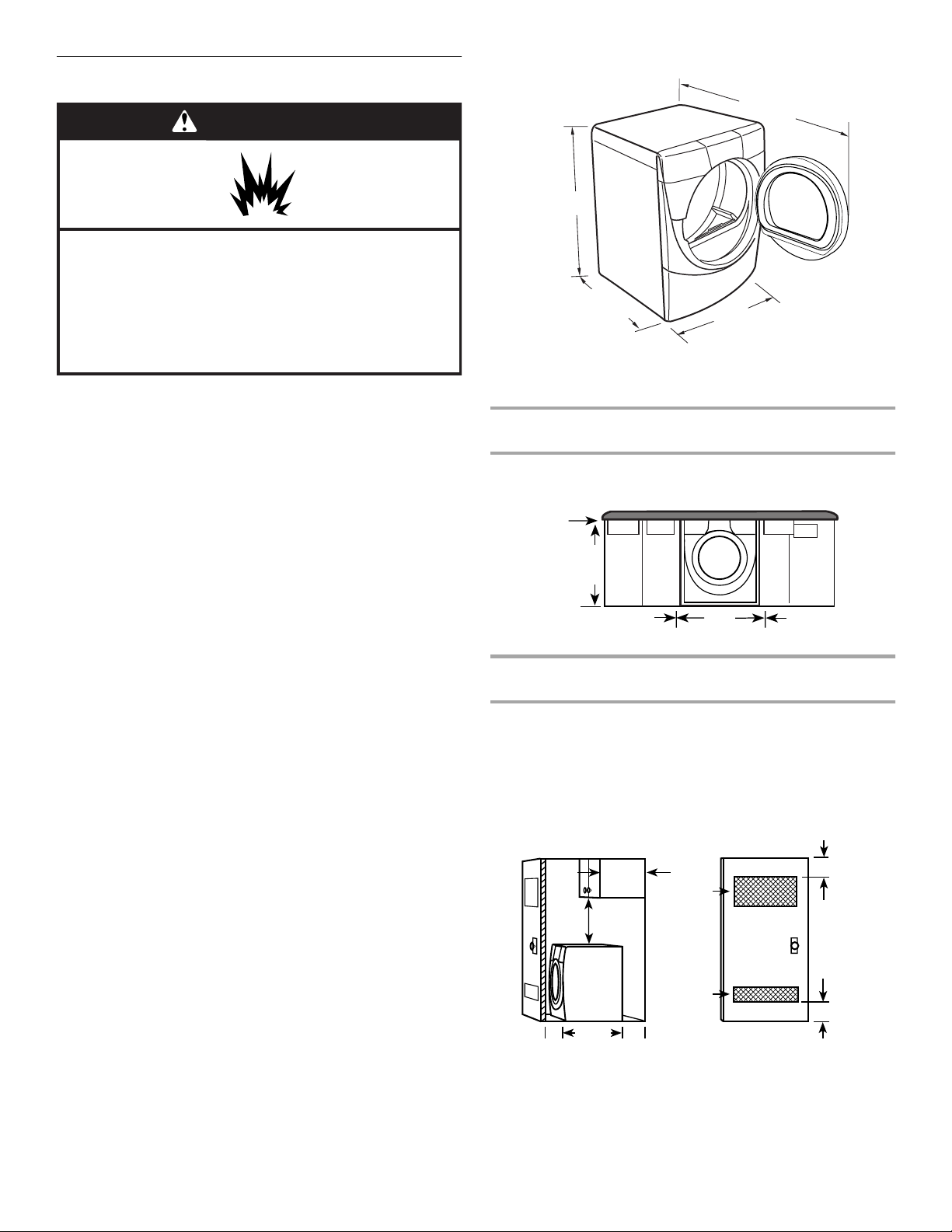
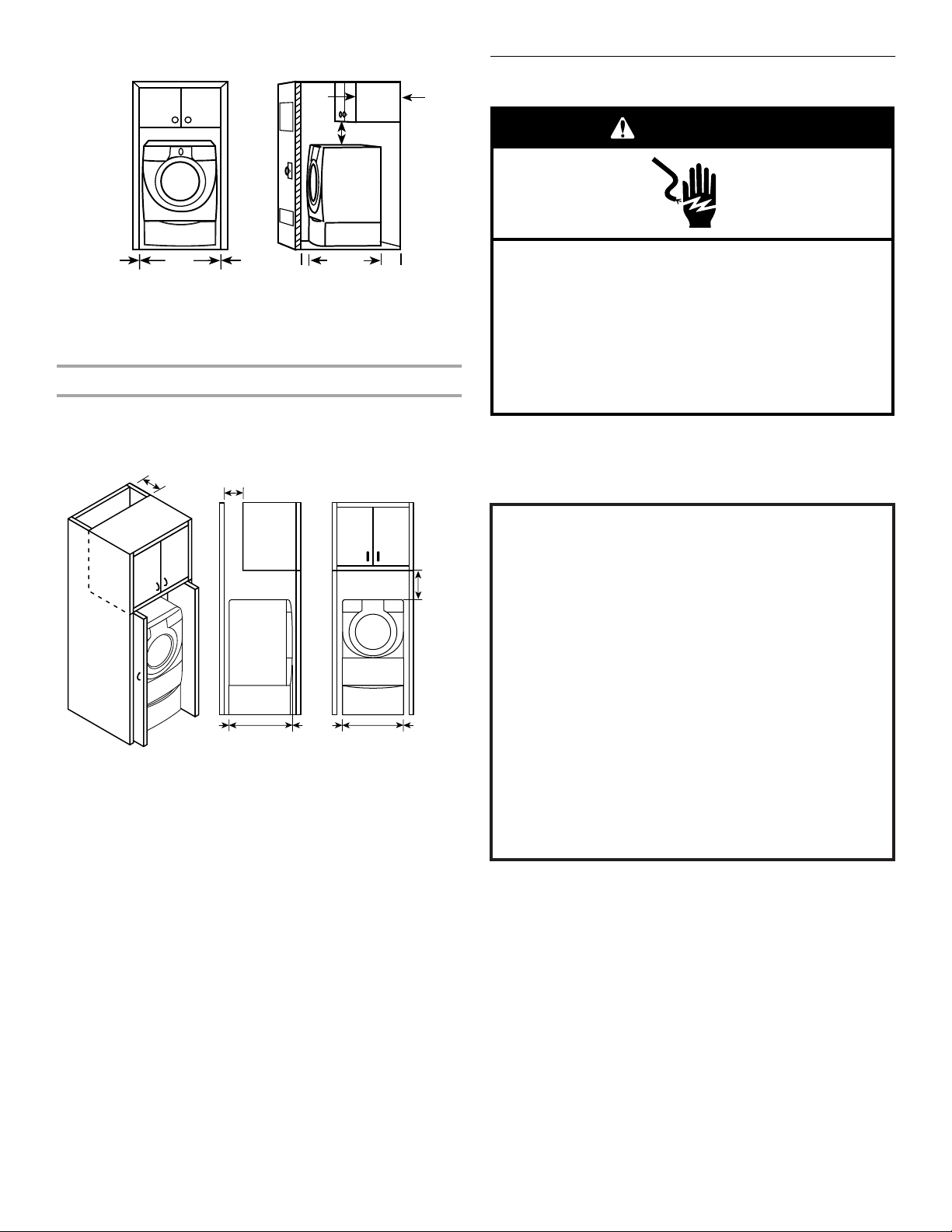
Dryer Dimensions
51½"
(130.81 cm)
38"
(96.52 cm)
*31½"
(80 cm)
27"
(68.6 cm)
*Most installations require a minimum 5½" (14 cm) clearance
behind the dryer for the exhaust vent with elbow. See “Venting
Requirements.”
Minimum installation spacing for custom undercounter
installation
The dimensions shown are for the minimum spacing allowed.
Custom undercounter installation - Dryer only
0"
(0 cm)
38" min.
(96.52 cm)
0"
(0 cm)
27"
(68.6 cm)
0"
(0 cm)
Minimum installation spacing for recessed or closet
installation, with or without a pedestal
■ The dimensions shown are for the minimum spacing allowed.
■ For closet installation, with a door, minimum ventilation
openings in the top and bottom of the door are required.
Louvered doors with equivalent ventilation openings are
acceptable.
Closet installation - Dryer only
3"
(7.6 cm)
3"
(7.6 cm)
0"
(0 cm)
18" min.
(45.72 cm)
31½"
(80 cm)
14" max.
(35.6 cm)
0"
(0 cm)
48 in.
(310 cm2)
24 in.
(155 cm2)
2
2
A
A. Side view - closet or confined area
B. Closet door with vents
B
6
Recessed or closet installation - Dryer on pedestal
)
14" max.
(35.6 cm)
18" min.
(45.72 cm)
Electrical Requirements
WARNING
0"
(0 cm)
27"
(68.6 cm)
0"
(0 cm)
0"
(0 cm)
31½"
(80 cm)
0"
(0 cm)
AB
A. Recessed area
B. Side view - closet or confined area
Minimum installation spacing for cabinet installation
■ The dimensions shown are for the minimum spacing allowed.
■ For cabinet installation, with a door, minimum ventilation
openings in the top of the cabinet are required.
7" (17.8 cm)
7" (17.8 cm)
9"
(22.9 cm
Electrical Shock Hazard
Plug into a grounded 3 prong outlet.
Do not remove ground prong.
Do not use an adapter.
Do not use an extension cord.
Failure to follow these instructions can result in death,
fire, or electrical shock.
■ 120-Volt, 60-Hz., AC-only, 15- or 20-amp fused electrical
supply is required. (Time-delay fuse or circuit breaker is
recommended.) It is recommended that a separate circuit
serving only this dryer be provided.
GROUNDING INSTRUCTIONS
■
For a grounded, cord-connected dryer:
This dryer must be grounded. In the event of malfunction or
breakdown, grounding will reduce the risk of electric shock
by providing a path of least resistance for electric current.
This dryer is equipped with a cord having an equipmentgrounding conductor and a grounding plug. The plug must
be plugged into an appropriate outlet that is properly
installed and grounded in accordance with all local codes
and ordinances.
0"
(0 cm)
31¹₂"
(80.0 cm)
0"
(0 cm)
0"
(0 cm)
27"
(68.6 cm)
0"
(0 cm)
Mobile home - Additional installation requirements
This dryer is suitable for mobile home installations. The installation must conform to the Manufactured Home Construction and
Safety Standard, Title 24 CFR, Part 3280 (formerly the Federal
Standard for Mobile Home Construction and Safety, Title 24,
HUD Part 280).
Mobile home installations require:
■ Metal exhaust system hardware which is available for
purchase from your dealer.
■ Mobile home Installation Kit Part Number 346764. See “Tools
and Parts” section for ordering information.
■ Special provisions must be made in mobile homes to
introduce outside air into the dryer. The opening (such as a
nearby window) should be at least twice as large as the dryer
exhaust opening.
WARNING:
Improper connection of the equipmentgrounding conductor can result in a risk of electric shock.
Check with a qualified electrician or service representative
or personnel if you are in doubt as to whether the dryer is
properly grounded. Do not modify the plug provided with the
dryer: if it will not fit the outlet, have a proper outlet installed
by a qualified electrician.
SAVE THESE INSTRUCTIONS
7
Gas Supply Requirements
WARNING
■ Must include a shutoff valve:
An individual manual shutoff valve must be installed within
six (6) feet (1.8 m) of the dryer in accordance with the National
Fuel Gas Code, ANSI Z223.1.
The location should be easy to reach for opening and closing.
Explosion Hazard
Use a new AGA or CSA approved gas supply line.
Install a shut-off valve.
Securely tighten all gas connections.
If connected to LP, have a qualified person make sure
gas pressure does not exceed 13" (33 cm) water
column.
Examples of a qualified person include:
licensed heating personnel,
authorized gas company personnel, and
authorized service personnel.
Failure to do so can result in death, explosion, or fire.
Gas Type
Natural gas:
This dryer is equipped for use with natural gas. It is designcertified by CSA International for L.P. (propane or butane) gases
with appropriate conversion.
■ Your dryer must have the correct burner for the type of gas in
your home. Burner information is located on the rating plate
in the door well of your dryer. If this information does not
agree with the type of gas available, contact your dealer or
call the phone numbers referenced in the “Assistance or
Service” section of this manual.
L.P. gas conversion:
Conversion must be made by a qualified technician.
No attempt shall be made to convert the appliance from the gas
specified on the model/serial rating plate for use with a different
gas without consulting the serving gas supplier.
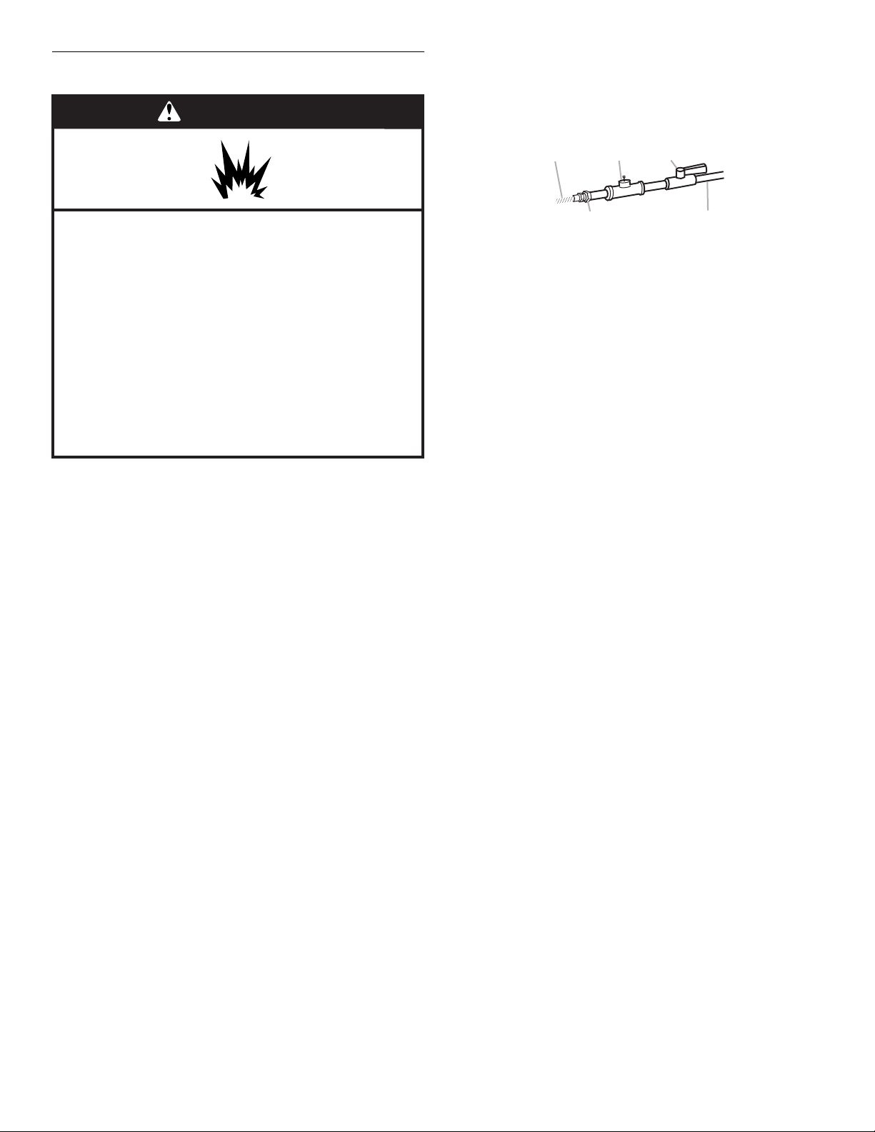
Gas supply line
■ ½" IPS pipe is recommended.
■ ³⁄₈" approved tubing is acceptable for lengths under
20 ft (6.1 m) if local codes and gas supplier permit.
■ Must include ¹⁄₈" NPT minimum plugged tapping accessible
for test gauge connection, immediately upstream of the gas
connection to the dryer (see following illustration).
A
C
B
A. ³⁄₈" flexible gas connector
B. ³⁄₈" pipe to flare adapter fitting
C. ¹⁄₈"
NPT plugged tapping
D. ½" NPT gas supply line
E. Gas shutoff valve
E
D
Gas supply connection requirements
There are many methods by which your gas dryer can be
connected to the gas supply. Listed here are some guidelines for
two different methods of connection.
Option 1 (Recommended method)
Flexible stainless steel gas connector:
■ If local codes permit, use a new flexible stainless steel gas
connector (Design Certified by the American Gas Association
or CSA International) to connect your dryer to the rigid gas
supply line. Use an elbow and a ³⁄₈" flare x ³⁄₈" NPT adapter
fitting between the stainless steel gas connector and the
dryer gas pipe, as needed to prevent kinking.
Option 2 (Alternate method)
Approved aluminum or copper tubing:
■ Lengths under 20 ft (6.1 m) can use ³⁄₈" approved tubing
(if codes and gas supplier permit).
■ If you are using natural gas, do not use copper tubing.
■ ³⁄₈" flare x ³⁄₈" NPT adapter fitting between dryer pipe and
³⁄₈" approved tubing.
■ Lengths over 20 ft (6.1 m) should use larger tubing and a
different size adapter fitting.
■ If your dryer has been converted to use L.P. gas, ³⁄₈" L.P.
compatible copper tubing can be used. If the total length of
the supply line is more than 20 ft (6.1 m), use larger tubing.
NOTE: Pipe joint compounds that resist the action of L.P. gas
must be used. Do not use TEFLON
®†
tape.
†®TEFLON isaregistered trademark of E.I. Du Pont De Nemoursand Company.
8
 Loading...