

Whirlpool WERP4101SB1, WERP3101SQ0, WERP3101SQ1, WERP3101SS0, WERP3101SB0 Installation Guide
...
INSTALLATIONINSTRUCTIONS
30" (76 CM) FREESTANDINGELECTRICRANGES
I_STRUCTIONS D'INSTALLATION DESCUISINIERES
ELECTRIQUESAUTOPORTANTESDE 30" (76 CM)
Table of Contentsrrable des mati@res
RANGE SAFETY ............................................... 2
INSTALLATION REQUIREMENTS .................. 3
Tools and Par_s ............................................. 3
Location Requirements ................................. 3
Electrical Requirements ................................ 4
INSTALLATION INSTRUCTIONS .................... 5
Unpack Range ............................................... 5
Install Anti-Tip Bracket .................................. 5
Verify Anti-Tip Bracket Location ................... 6
Level Range ................................................... 6
Complete Installation ..................................... 7
Moving the Range ......................................... 7
ANTI-TIP BRACKET TEMPLATE ................. 16
SI_CURITI_ DE LA CUISINII_RE ....................... 9
EXIGENCES D'INSTALLATION ..................... 10
Outillage et pi_ees ....................................... 10
Exigenoes d'emplacement .......................... 10
Specifications _lectriques ............................ 11
INSTRUCTIONS D'INSTALLATION ............... 12
D_ballage de lacuisiniere ............................ 12
Installation de la bride antibasculement ......12
V_rification de I'emplacement
de la bride anti-basculement ....................... 13
Mise & niveau de lacuisiniere ...................... 13
Achever I'installation .................................... 14
D_placement de la cuisiniere ....................... 14
GABARIT POUR LA BRIDE
ANTIBASCULEMENT ..................................... 16
iMPORTANT:
Save for Iocal electrical inspector's use.
_nstaHer: Leave installation instructions with the homeowner.
Homeowner: Keep installation instructions for future reference.
iMPORTANT :
/_ conserver pour consultation par Hnspecteur local des installations electriques_
_netaHateur : Remettre Ies instructions d'installation au proprietaire.
Proprietaire : Conserver les instructions d'installation pour reference ulterieure.
9762182
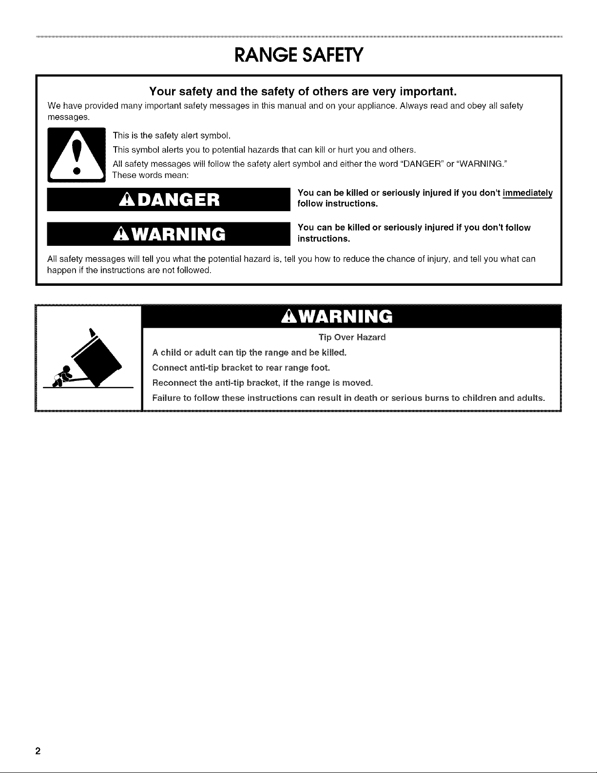
RANGE SAFETY
Your safety and the safety of others are very important.
We have provided many important safety messages in this manual and on your appliance. Always read and obey all safety
messages.
This is the safety alert symbol.
This symbol alerts you to potential hazards that can kill or hurt you and others.
All safety messages will follow the safety alert symbol and either the word "DANGER" or "WARNING."
These words mean:
You can be killed or seriously injured if you don't immediately
follow instructions.
You can be killed or seriously injured if you don't follow
instructions.
All safety messages will tell you what the potential hazard is, tell you how to reduce the chance of injury, and tell you what can
happen if the instructions are not followed.
Tip Over Hazard
A child or adult can tip the range and be killed.
Connect anti-tip bracket to rear range foot.
Reconnect the antFtip bracket, if the range is moved.
Faimureto fo(Iow these instructions can result in death or serious burns to cMIdren and adults.
INSTALLATIONREQUIREMENTS
Gather the required tools and parts before starting installation.
Read and follow the instructions provided with any tools listed
here.
Tools needed
• Tape measure • %" drive ratchet
• Flat-blade screwdriver • 1A"nut driver
• Level • %" and s_6" nut driver
• Hammer • 1/s"(3.2 mm) drill bit (for
• Hand or electric drill wood floors)
• Channel lock pliers • 3_6"(4.8 mm) carbide-tipped
• Marker or pencil concrete/ceramic floors)
• Masking tape
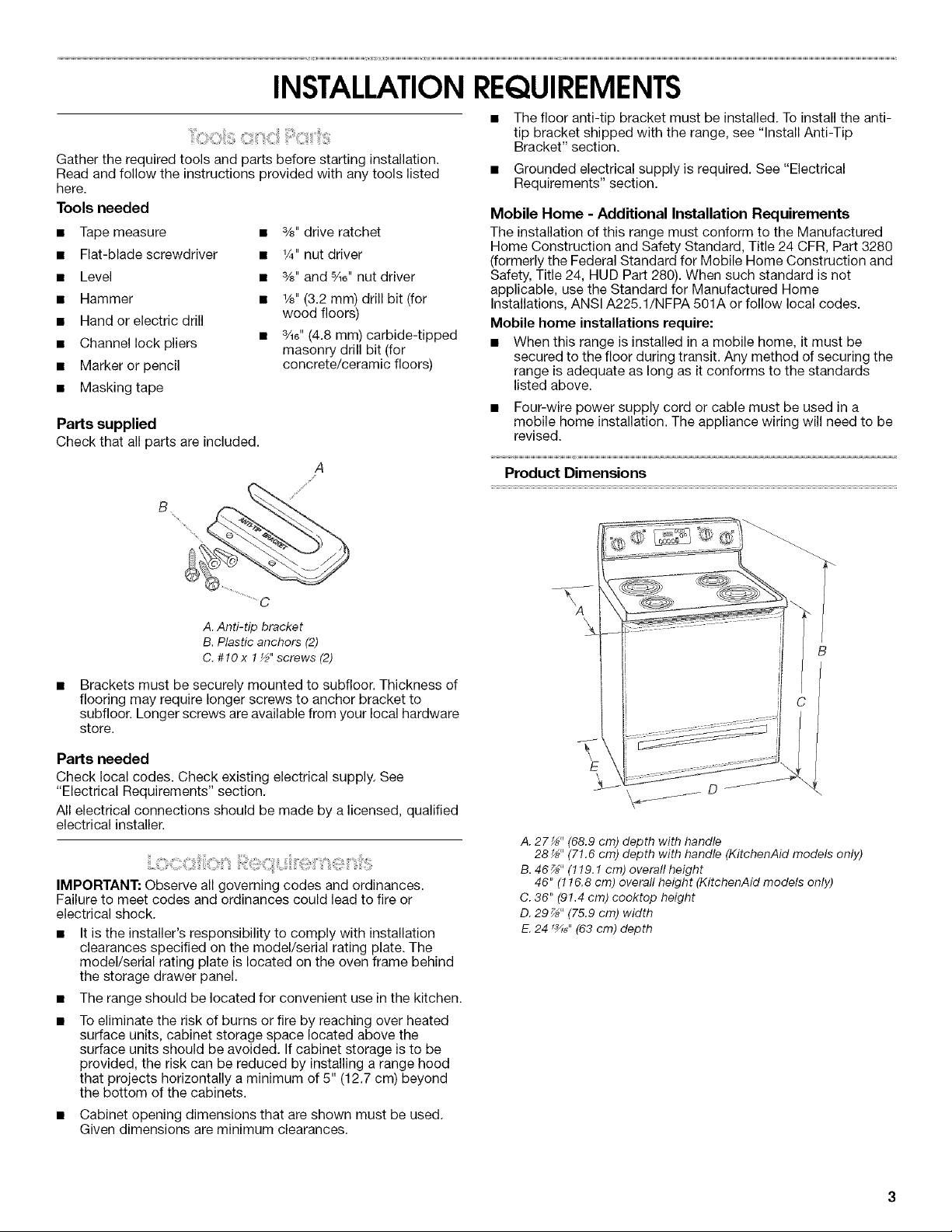
Parts supplied
Checkthat all parts are included.
masonry drill bit (for
A
The floor anti-tip bracket must be installed. To install the anti-
tip bracket shipped with the range, see "Install Anti-Tip
Bracket" section.
Grounded electrical supply is required. See "Electrical
Requirements" section.
Mobile Home - Additional Installation Requirements
The installation of this range must conform to the Manufactured
Home Construction and Safety Standard, Title 24 CFR, Part 3280
(formerly the Federal Standard for Mobile Home Construction and
Safety, Title 24, HUD Part 280). When such standard is not
applicable, use the Standard for Manufactured Home
Installations, ANSI A225.1/NFPA 501A or follow local codes.
Mobile home installations require:
• When this range is installed in a mobile home, it must be
secured to the floor during transit. Any method of securing the
range is adequate as long as it conforms to the standards
listed above.
• Four-wire power supply cord or cable must be used in a
mobile home installation. The appliance wiring will need to be
revised.
Product Dimensions
A. Anti-tip bracket
B. Plastic anchors (2)
C.#1Ox !½"screws(2)
Brackets must be securely mounted to subfloor. Thickness of
flooring may require longer screws to anchor bracket to
subfloor. Longer screws are available from your local hardware
store.
Parts needed
Check local codes. Check existing electrical supply. See
"Electrical Requirements" section.
All electrical connections should be made by a licensed, qualified
electrical installer.
IMPORTANT: Observe all governing codes and ordinances.
Failure to meet codes and ordinances could lead to fire or
electrical shock.
• It is the installer's responsibility to comply with installation
clearances specified on the model/serial rating plate. The
model/serial rating plate is located on the oven frame behind
the storage drawer panel.
• The range should be located for convenient use in the kitchen.
• To eliminate the risk of burns or fire by reaching over heated
surface units, cabinet storage space located above the
surface units should be avoided. If cabinet storage is to be
provided, the risk can be reduced by installing a range hood
that projects horizontally a minimum of 5" (12.7 cm) beyond
the bottom of the cabinets.
• Cabinet opening dimensions that are shown must be used.
Given dimensions are minimum clearances.
A. 27 _" (68.9 cm) depth with handle
28 _" (71.6 cm) depth with handle (KitchenAid models only)
B. 46 _" (119.1 cm) overafl height
46" (116.8 cm) overall height (KitchenAid models only)
C. 36" (91.4 cm) cooktop height
D. 29_" (75.9 cm) width
E.24 1_6" (63 cm) depth
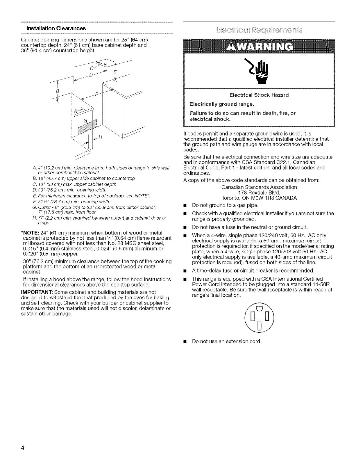
Installation Clearances
Cabinet opening dimensions shown are for 25" (64 cm)
countertop depth, 24" (61 cm) base cabinet depth and
36" (91.4 cm) countertop height.
A. 4" (10.2 cm) min. clearance from both sides of range to side wall
or other combustible material
B. 18" (45.7 cm) upper side cabinet to countertop
C. 13" (33 cm) max. upper cabinet depth
D. 30" (76.2 cm) min. opening width
E.For minimum clearance to top of cooktop, see NOTE*.
F. 31 _" (78.7 cm) min. opening width
G. Outlet - 8" (20.8 cm) to 22" (55.9 cm) from either cabinet,
7" (17.8 cm) max. from floor
H. _" (2.2 cm) min. required between cutout and cabinet door or
hinge
*NOTE: 24" (61 cm) minimum when bottom of wood or metal
cabinet is protected by not less than 1/4"(0.64 cm) flame retardant
millboard covered with not less than No. 28 MSG sheet steel,
0.015" (0.4 mm) stainless steel, 0.024" (0.6 mm) aluminum or
0.020" (0.5 mm) copper.
30" (76.2 cm) minimum clearance between the top of the cooking
platform and the bottom of an unprotected wood or metal
cabinet.
If installing a hood above the range, follow the hood instructions
for dimensional clearances above the cooktop surface.
IMPORTANT: Some cabinet and building materials are not
designed to withstand the heat produced by the oven for baking
and self-cleaning. Check with your builder or cabinet supplier to
make sure that the materials used will not discolor, delaminate or
sustain other damage,
Electrica_ Shock Hazard
EmectricaHy ground range.
Failure to do so can result in death, fire, or
electrica_ shock.
If codes permit and a separate ground wire is used, it is
recommended that a qualified electrical installer determine that
the ground path and wire gauge are in accordance with local
codes.
Be sure that the electrical connection and wire size are adequate
and in conformance with CSA Standard C22.1, Canadian
Electrical Code, Part 1 - latest edition, and all local codes and
ordinances.
A copy of the above code standards can be obtained from:
Canadian Standards Association
178 Rexdale Blvd.
Toronto, ON M9W 1R3 CANADA
• Do not ground to a gas pipe.
• Check with a qualified electrical installer if you are not sure the
range is properly grounded.
• Do not have a fuse in the neutral or ground circuit.
• When a 4-wire, single phase 120/240 volt, 60 Hz., AC only
electrical supply is available, a 50-amp maximum circuit
protection is required (or, if specified on the model/serial rating
plate, when a4-wire, single phase 120/208 volt 60 Hz., AC
only electrical supply is available, a 40-amp maximum circuit
protection is required), fused on both sides of the line.
• A time-delay fuse or circuit breaker is recommended.
• This range is equipped with a CSA International Certified
Power Cord intended to be plugged into a standard 14-50R
wall receptacle. Be sure the wall receptacle is within reach of
range's final location.
• Do not use an extension cord.
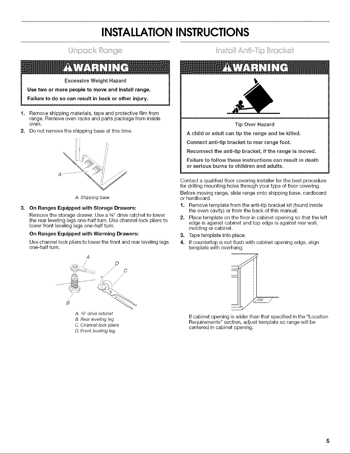
INSTALLATIONINSTRUCTIONS
Excessive Weight Hazard
Use two or more people to move and install range.
Failure to do so can result in back or other injury.
I=
Remove shipping materials, tape and protective film from
range. Remove oven racks and parts package from inside
oven,
2.
Do not remove the shipping base at this time.
//
A. Shipping base
3=
On Ranges Equipped with Storage Drawers:
Remove the storage drawer. Use a 3/8"drive ratchet to lower
the rear leveling legs one-half turn. Use channel lock pliers to
lower front leveling legs one-half turn.
On Ranges Equipped with Warming Drawers:
Use channel lock pliers to lower the front and rear leveling legs
one-half turn.
A
/'
D
"/'¢' C
Tip Over Hazard
A child or adumt can tip the range and be kiJled.
Connect antFtip bracket to rear range foot.
Reconnect the antFtip bracket, if the range is moved.
Failure to follow these instructions can resumt in death
or serious burns to children and adumts.
Contact a qualified floor covering installer for the best procedure
for drilling mounting holes through your type of floor covering.
Before moving range, slide range onto shipping base, cardboard
or hardboard.
1. Remove template from the anti-tip bracket kit (found inside
the oven cavity) or from the back of this manual.
2. Place template on the floor in cabinet opening so that the left
edge is against cabinet and top edge is against rear wall,
molding or cabinet.
3. Tape template into place.
4. If countertop is not flush with cabinet opening edge, align
template with overhang.
z ',
A. _" drive ratchet
B. Rear leveling leg
C. Channel lock pliers
D. Front leveling leg
If cabinet opening is wider than that specified in the "Location
Requirements" section, adjust template so range will be
centered in cabinet opening.
 Loading...