

Page 1
CONSUMER SERVICES TECHNICAL
EDUCATION GROUP PRESENTS
G-21
USING TEST EQUIPMENT
JOB AID
Part No. 4322537A
Page 2

Page 3

THE VOLT-OHMMETER (VOM)
INTRODUCTION
The volt-ohmmeter, usually referred to as a ”VOM,” or ”Multimeter,”
combines two individual instruments into one. These instruments are
the:
• Ohmmeter for measuring resistance (in ohms - Ω).
• Voltmeter for measuring voltage (AC and DC).
Technicians prefer the convenience of this single meter that combines
both measuring functions. Some multimeters offer other functions, such
as AC ampere, DC millivolt, and temperature measurements.
1
Page 4

FEATURES & FUNCTIONS
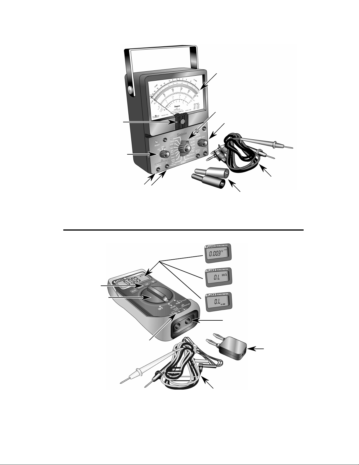
Most VOMs offer the following standard features and functions:
DISPLAY — The window that shows the variable pointer, and the
printed measuring scales for the different types of readings. A digital
VOM does not use a pointer or printed scales. Instead, it displays its
measurements in actual numbers.
RANGE SELECTOR — A rotary switch that performs two functions:
1. Chooses the type of reading (AC volts, DC volts, and Ohms) to be
measured.
2. Selects the range of the highest expected reading. Some meters
use jacks instead of a selector switch, or a combination of jacks
and switches.
METER ZERO ADJUST — A control (usually a screw or knob) that
aligns the pointer with the zero mark on the measuring scales to in-
crease accuracy.
OHMS ZERO ADJUST — A control (usually a small knob) that aligns
the pointer with the zero mark on the Ohms scale. An internal battery
supplies a small voltage for making resistance measurements. As the
condition of the battery changes over time, the Ohms Zero Adjust con-
trol allows the user to easily zero the pointer to compensate for these
changes.
PROBE JACKS — Connection terminals for the test leads that are used
to make electrical measurements. The jacks and terminals are marked
with a (+) and a (–) symbol. They are also color-coded (usually red and
black) to ensure proper connections and polarity when making DC
measurements. If the leads are reversed when making a DC voltage
reading, the meter pointer will move in the direction opposite of the
meter scale. Some meters have a polarity reversing switch that inter-
nally reverses the (+) and (–) leads when the range switch is set to DC.
2
Page 5
Display
Range Switch
Mechanical Zero Adjust
AC-DC Selector
Range Selectors
Ohms Zero Adjust
Test Leads
Probe Jacks
Alligator Clips
Figure 1
Simpson 260 Series 6XLMP Meter
Display
Voltage & Resistance
Selector
Probe Jacks
Temperature Probe Jacks
Temperature Adapter
Test Leads
Figure 2
Fluke 16 Multimeter
3
Page 6

HOW THE METER MOVEMENT OPERATES
In order for the VOM to register a measurement, the meter’s pointer
must be made to move, or rotate, across the scale. For this to happen,
the base of the pointer is mounted on a pivot, and placed between the
poles of a permanent magnet. In addition, a coil of very fine wire is
wound around the base of the pointer.
As current passes through the coil, a small magnetic field is produced.
This field reacts with the field produced by the permanent magnet. The
amount of pointer movement is determined by the amount of current
passing through the coil, and the size of its magnetic field.
When current stops flowing through the coil, the pointer returns to zero.
It is very important to handle a VOM carefully, since a sudden jolt can
unseat the pointer from its pivot, and damage the movement.
4
Page 7

MAKING ACCURATE MEASUREMENTS
To make your measurements as accurate as possible, use the following
steps:
1. Carefully read the operating instructions and safety information in the
VOM manual.
2. Check the meter and make sure that the pointer is set to “zero.” Use
the Mechanical Zero Adjust for the voltage scale, and the Ohm Zero
Adjust for the resistance (Ω) scale.
3. Make sure that the test leads are firmly inserted into their jacks.
Insert the black test lead into the negative (–) jack, and the red test
lead in the positive (+) jack.
4. When making a measurement, keep the metal probe tips firmly in
contact with the leads of the device being tested to insure good
metal-to-metal contact. Poor contact will cause inaccurate or fluctuat-
ing readings.
5. Do not touch the metal probes while taking a measurement. If you
touch the probes during that time, you could receive a serious electri-
cal shock. Touching the metal probes while making a resistance
measurement can cause the reading to be inaccurate because of
skin resistance.
6. Always select the range that will provide a midscale reading for the
resistance you want to measure.
5
Page 8
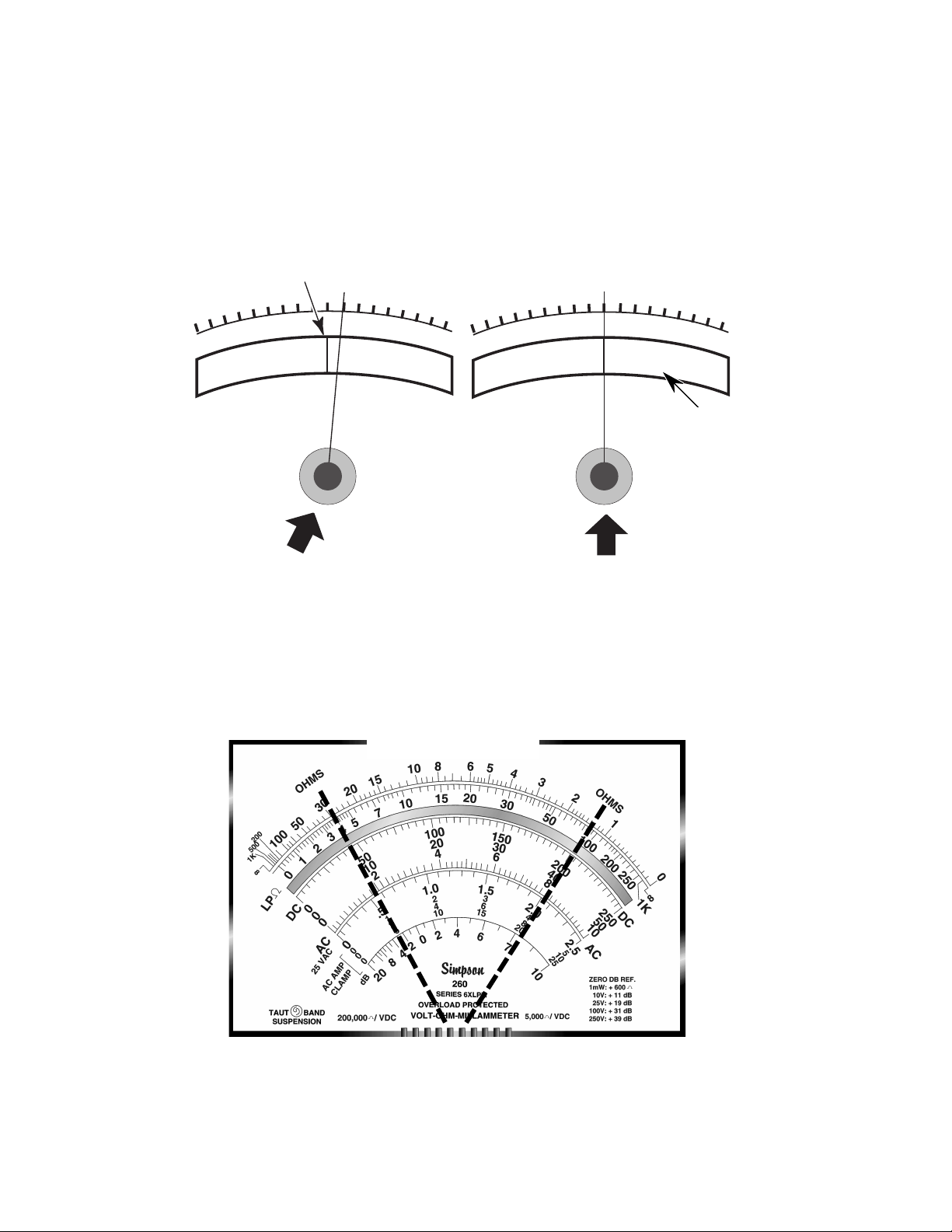
7. Look straight at the meter pointer and scale. If you view them at an
angle, you can get an inaccurate reading. Some meters have a
mirrored scale to help prevent reading errors. With this type of scale,
you know that you are viewing straight if the pointer hides its reflec-
tion in the mirror (see Figure 3).
Pointer Reflection
No Pointer Reflection
Mirror
Figure 3
Incorrect Eye Position
Correct Eye Position
8. Select the appropriate voltage or resistance range so that the read-
ings are in the center portion of the scale. This will give a more accu-
rate reading (see Figure 4).
Midrange Viewing
Figure 4
6
Page 9
RESISTANCE
MEASURING RESISTANCE (Ω)
When a resistance measurement is made, the test probes connect the
meter in series with the component, or load. To prevent damage to the
meter during a resistance measurement, the circuit or component is
always disconnected from the power source.
A very small current is needed to obtain a resistance measurement, and
is provided by a battery inside the VOM.
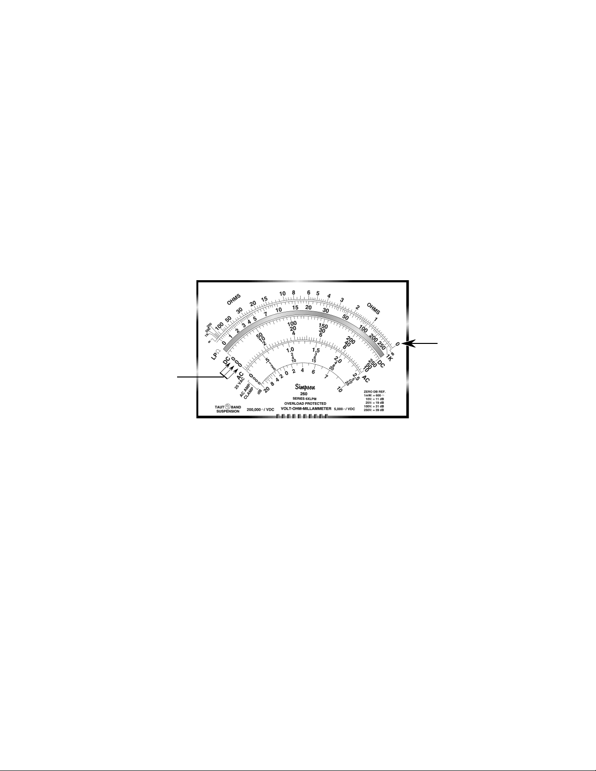
Note that the resistance, or ohm’s scale (Ω) of the meter, is the reverse
of the volts scales (see Figure 5). That is, the zero on each scale is at
the opposite ends of the meter.
Zero
Ohms
Zero
Volts
Less Current Flow
More Resistance
When the maximum amount of current is flowing through the circuit, the
pointer will rotate all the way to the zero end of the ohms scale.
When very little current is flowing, the pointer will remain at, or near, the
infinity (∞), or maximum resistance, end of the ohms scale. The Range
switch has various resistance values built into the meter, which allows
for the proper measurement of resistance.
Before making a resistance reading, any changes in the battery condi-
tion must be compensated for to assure accuracy. In order to do this:
1. Touch the test lead probe tips together to obtain the maximum cur-
rent flow from the battery.
Figure 5
More Current Flow
Less Resistance
2. Zero the resistance scale pointer with the Ohms Zero Adjustment
knob.
3. Zero the meter each time the range switch is changed.
7
Page 10
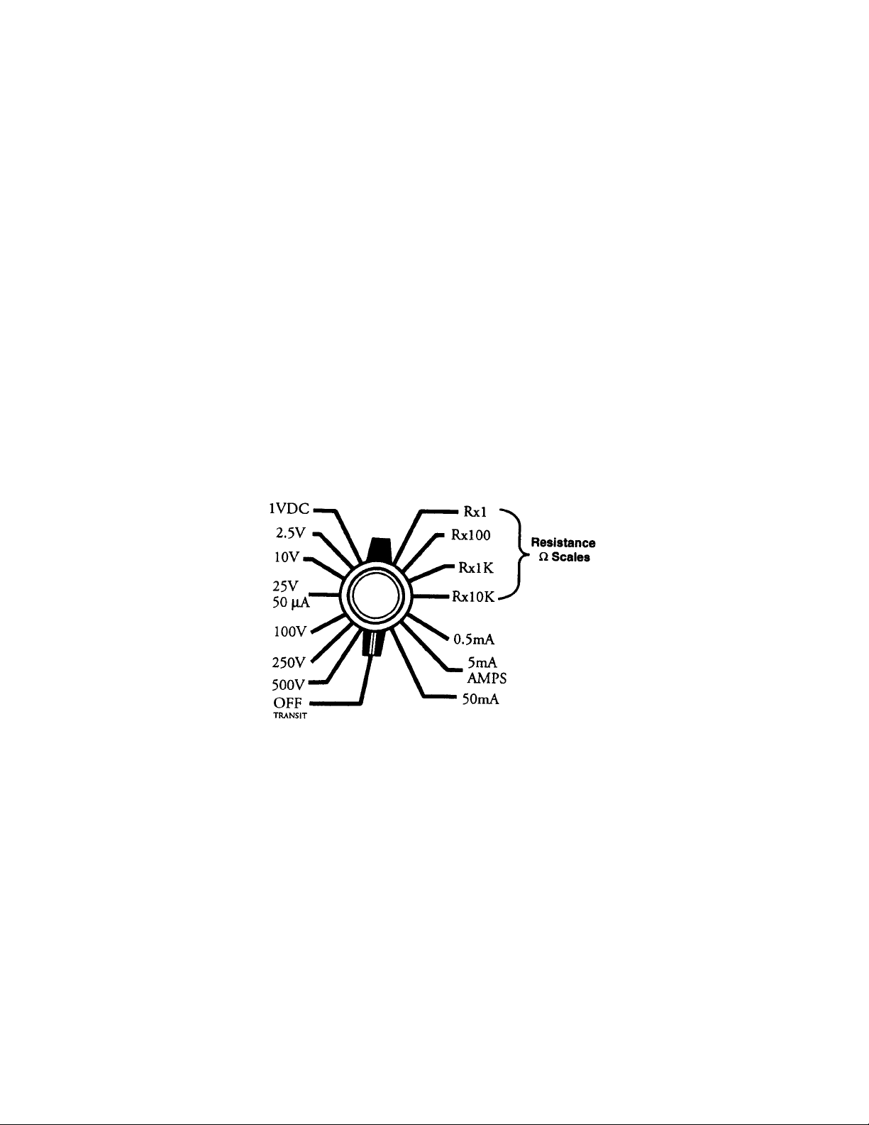
CHOOSING THE CORRECT RESISTANCE RANGE
Four resistance ranges are available on the meter, as shown in Figure
6. Each of these ranges show the user how much to multiply the meter
indication by. The four range scales are read as follows:
a) R x 1 = Reading on Scale x 1.
b) R x 100 = Reading on Scale x 100.
c) R x 1 K = Reading on Scale x 1,000.
d) R x 10K = Reading on Scale x 10,000.
The easiest way to remember how much to add to the meter reading, is
to add zeros to it. For example, if the meter indicates 5, and the Range
switch is set to R x 100, then adding two zeros to the 5, would equal
500. If the meter indicates 37 and the Range switch is set to R x 10K,
then adding four zeros (10,000) would make the reading 370,000.
Figure 6
8
Page 11
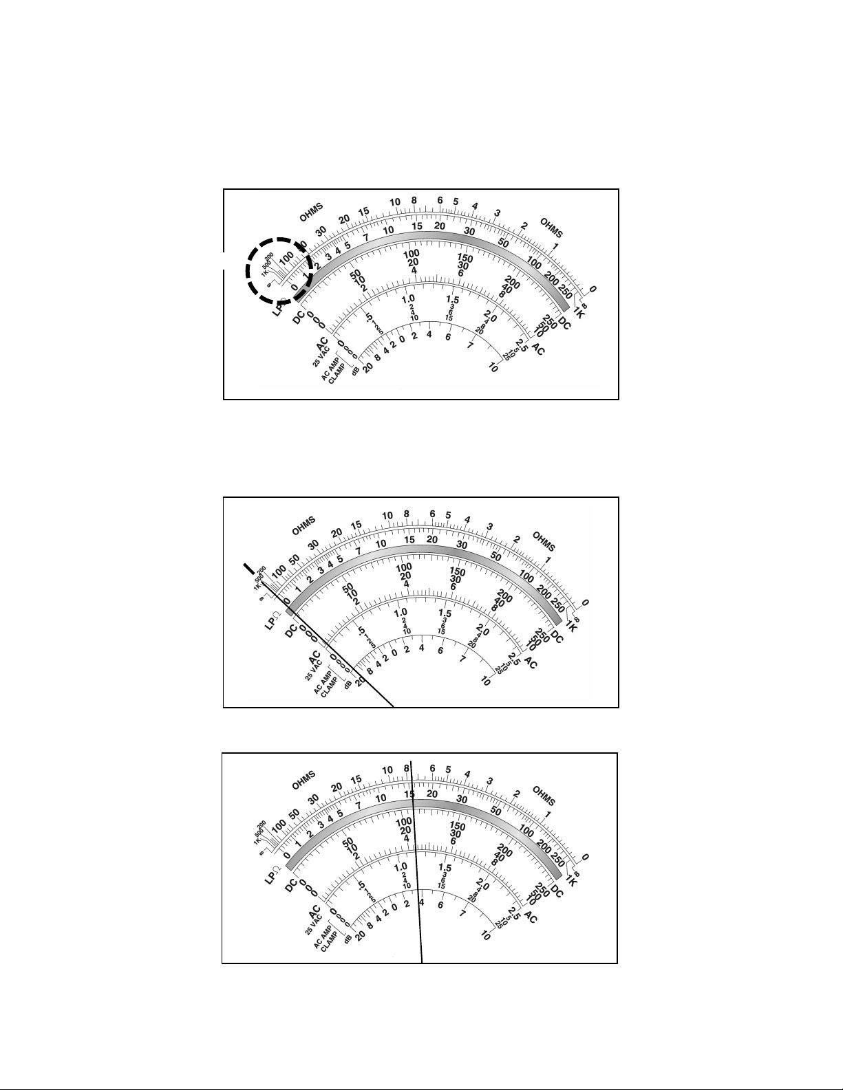
Unlike voltage scales, the scale used for resistance measurements is
not divided into equally-spaced increments. As resistance becomes
higher, the numbers on the scale are grouped closer together, making
an accurate reading difficult (see Figure 7).
Difficult Viewing
Figure 7
When making resistance measurements, it is important to try to get a
lower, or “midscale” reading, whenever possible (see Figure 8).
750 Ω On R x 1 Scale
750 Ω On R x 100 Scale
Figure 8
9
Page 12
MEASURING CONTINUITY
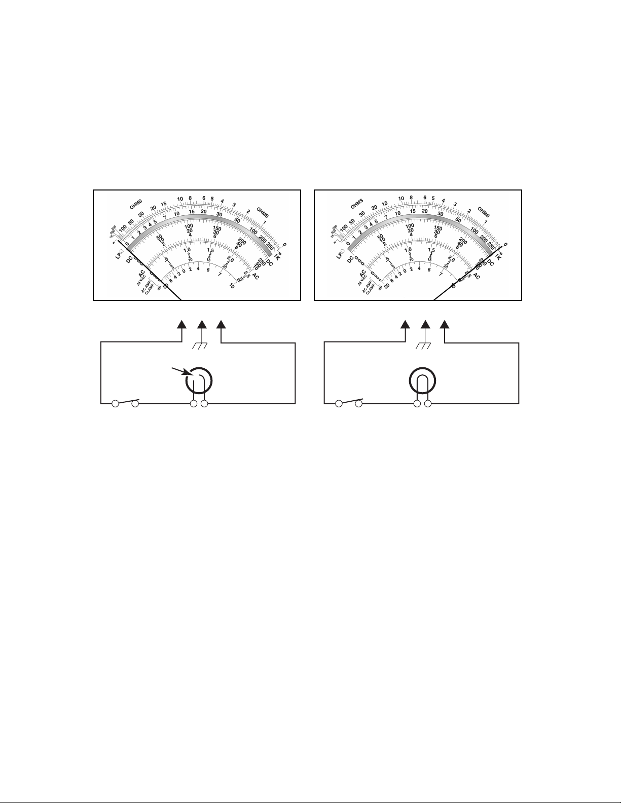
The ohmmeter can also be used to check continuity in a circuit. Continu-
ity is a “continuous,” or “closed” circuit. An open circuit means that the
continuous circuit has been broken at some point. In this case, the
meter would indicate “infinite” resistance.
Figure 9 shows an open and a closed circuit.
AB
AB
Open
Infinite Resistance
Open Circuit
Figure 9
0 Ω Resistance
Closed Circuit
BASIC RULES FOR MEASURING RESISTANCE
When making a resistance measurement, remember several basic
rules:
a) Always disconnect the circuit, or component being checked, from
the voltage source before connecting the meter probes.
b) Isolate the component being checked by disconnecting one side
of the component from the circuit. This assures that meter current
will flow only through the component being checked.
c) Use the Range switch, and select the resistance range you will be
measuring.
d) Zero the meter with the Zero Ohms Adjust knob.
10
Page 13
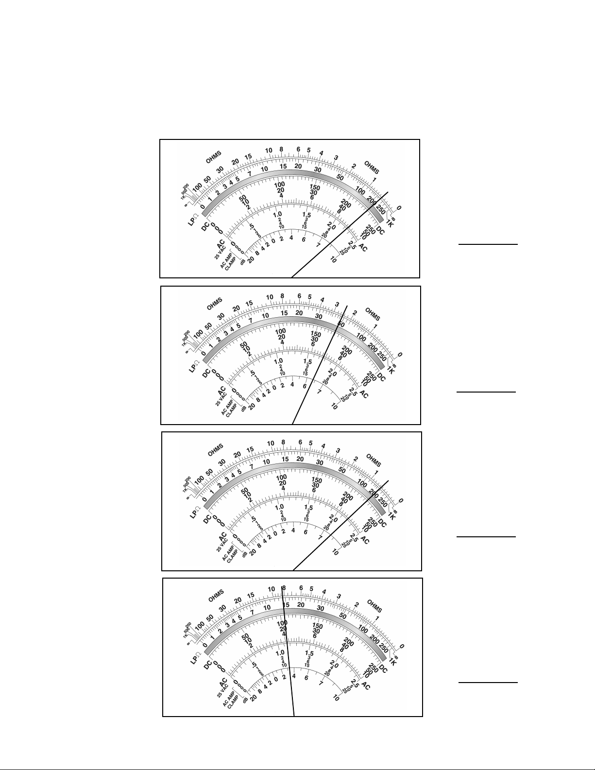
PRACTICE EXERCISE 1
READING THE RESISTANCE SCALE
Write the correct resistance reading in the space provided by each
illustration. The resistance ranges are shown.
1.
2.
R x 10K
R x 1K
3.
4.
R x 1
R x 100
11
Page 14
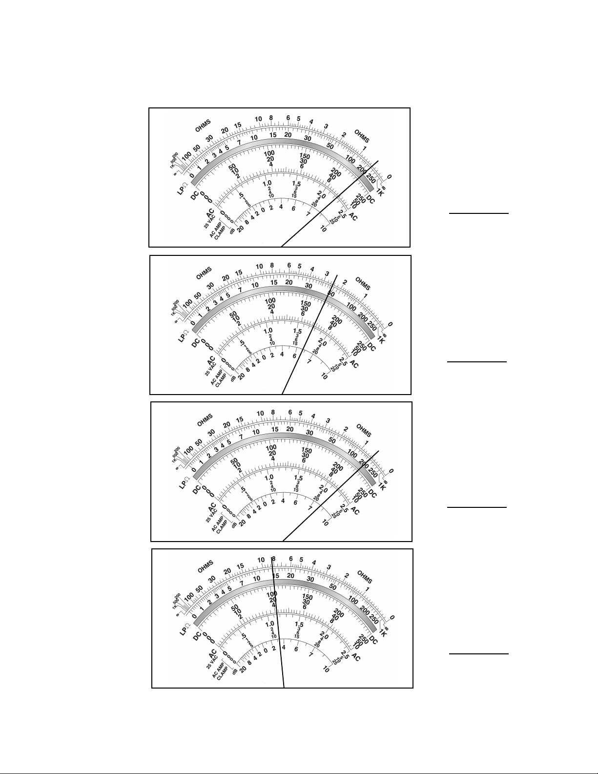
PRACTICE EXERCISE 1 ANSWERS
READING THE RESISTANCE SCALE
1.
2.
R x 10K
5000 Ω
R x 1K
3.
4.
2500 Ω
R x 1
.6 Ω
R x 100
12
820 Ω
Page 15
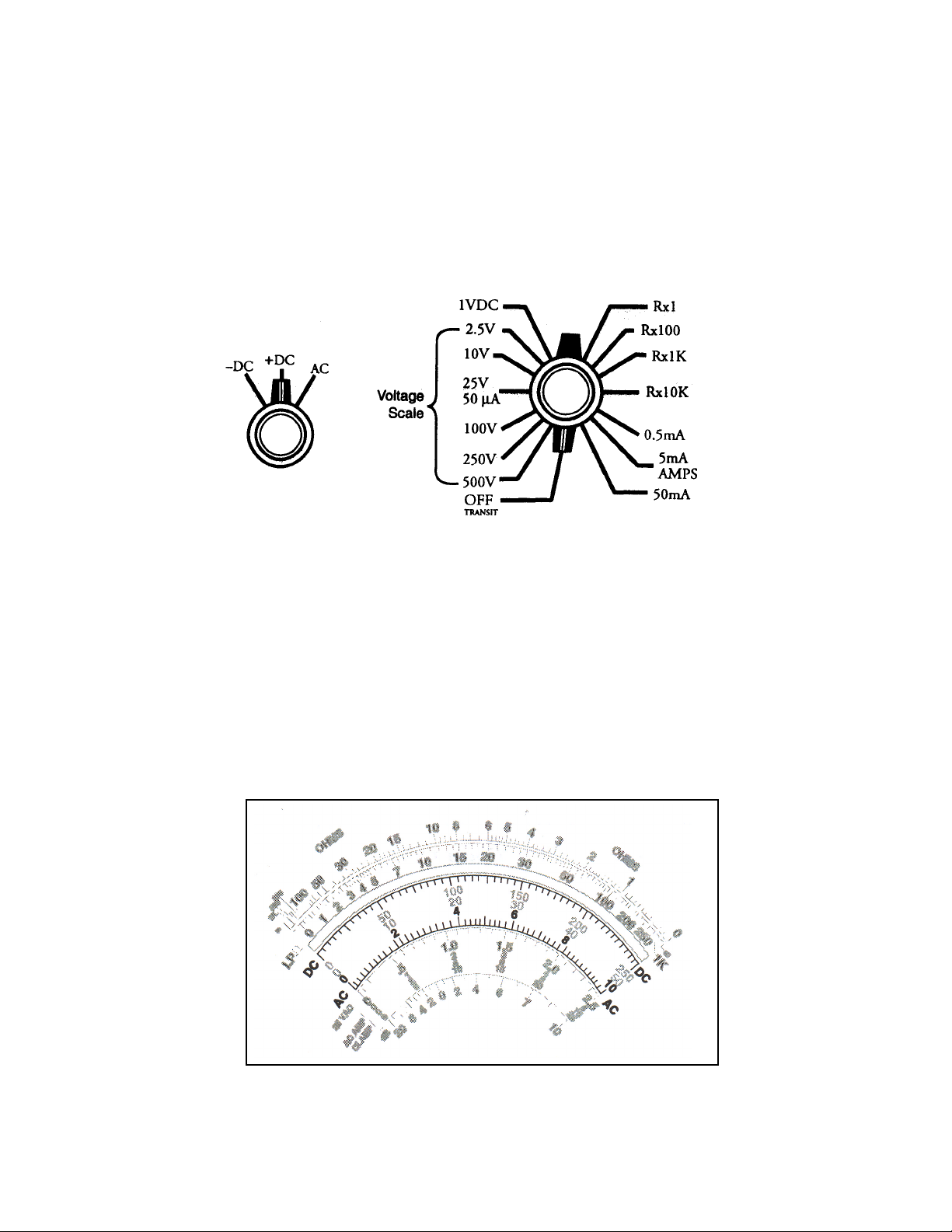
VOLTAGE
THE RANGE SWITCH
The Range switch has various settings for DC volts and for AC volts.
Both types of voltage have ranges with six settings: 2.5, 10, 25, 100,
250, and 500 volts (see Figure 10). The AC - DC Selector switch selects
the type of voltage being measured (–DC, +DC, AC).
Figure 10
THE VOLTAGE SCALE
The meter has three scales which are divided into the following incre-
ments (see Figures 11 A, B, & C). NOTE: The small division lines be-
tween the numbers on the scales help make the readings more exact:
a) The 0 - 10 scale is used to read voltages when the 10 or 100 volt
ranges are selected.
Figure 11A
13
Page 16
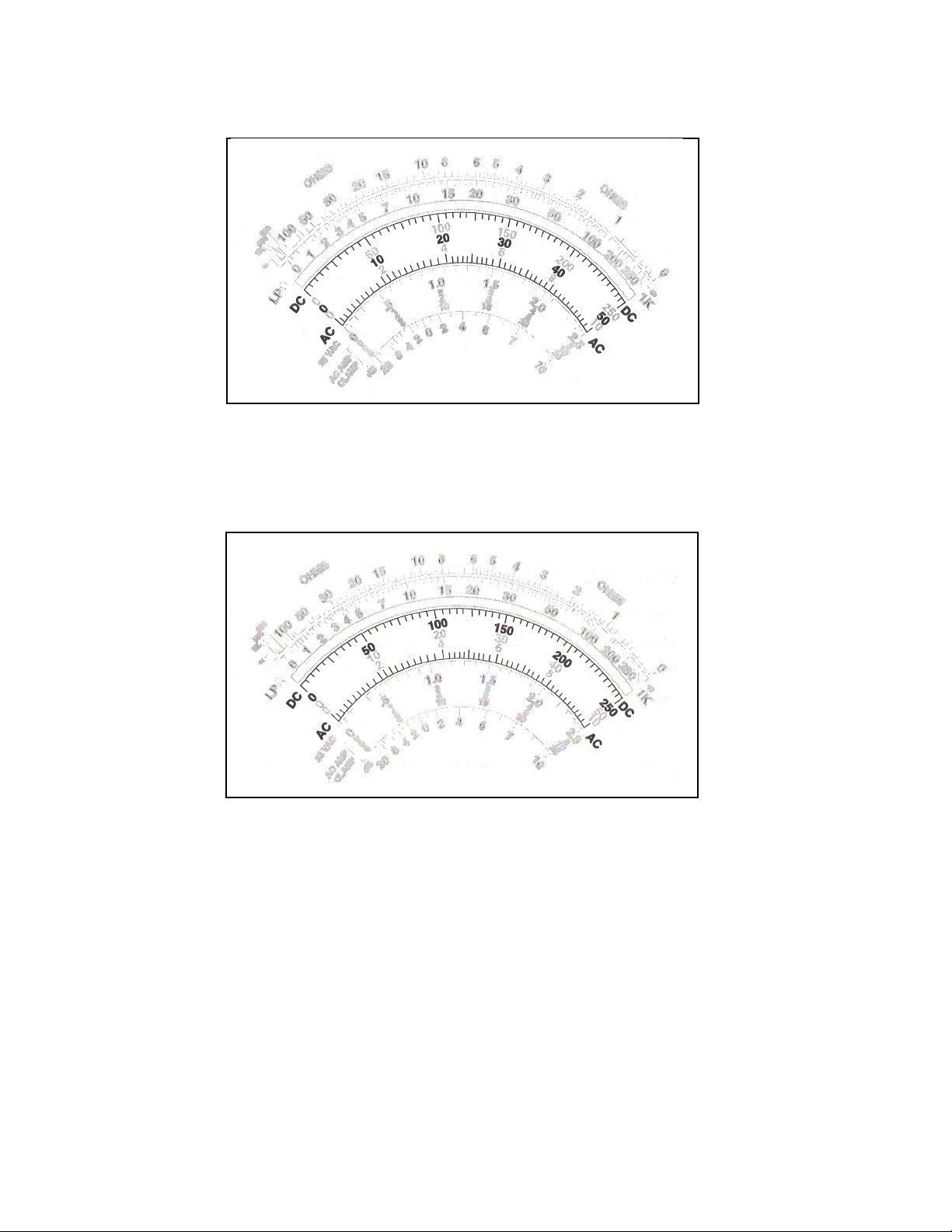
b) The 0 - 50 scale is used with the 500 volt range.
Figure 11B
c) The 0 - 250 scale is used with the 2.5, 25, or 250 volt ranges.
Figure 11C
14
Page 17
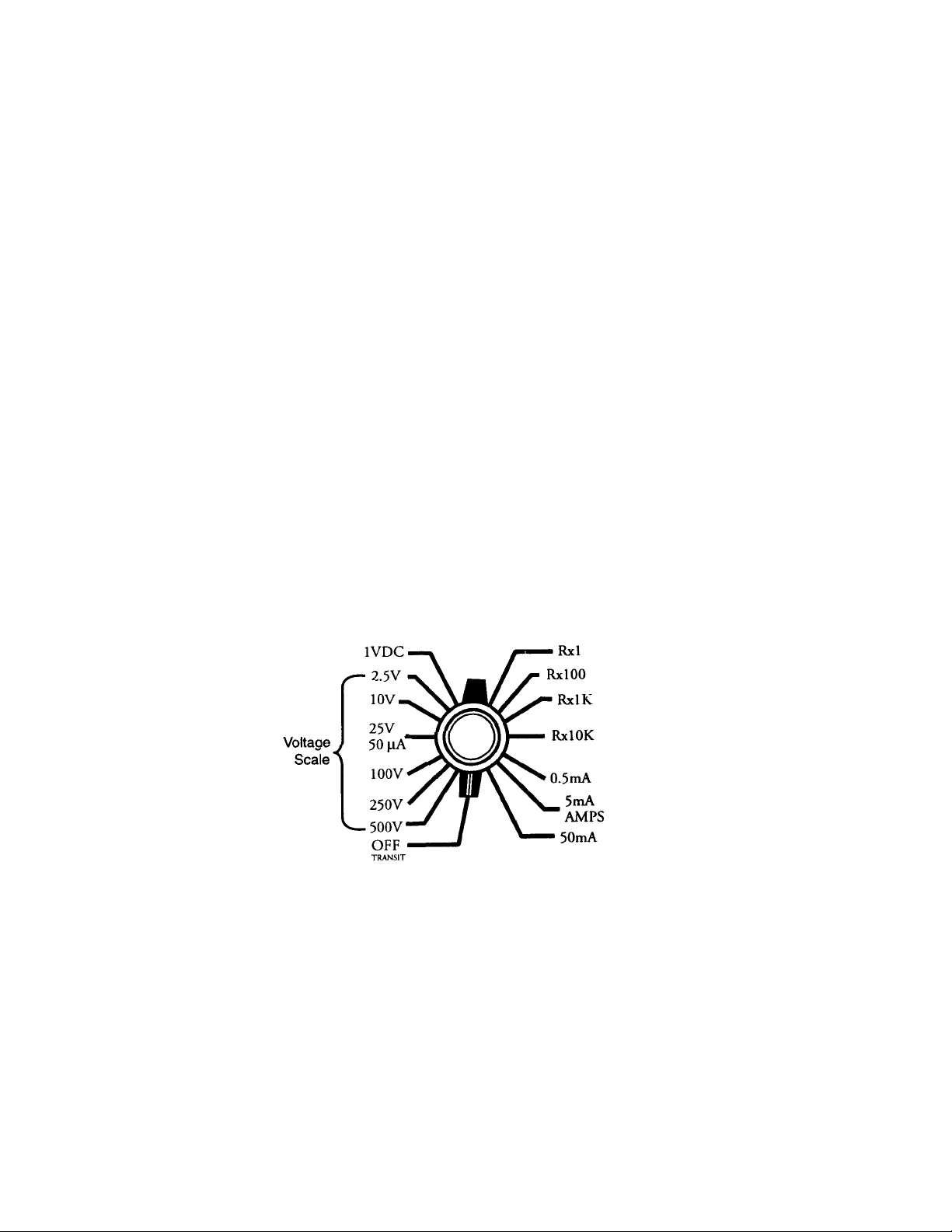
CHOOSING THE CORRECT VOLTAGE RANGE
Six voltage ranges are available on the meter, as shown in Figure 12.
Note that each one of the ranges has numbers that correspond to the
three meter scales. The Range switch and meter scales correspond to
each other in the following manner:
a) 2.5V Range = the 0 - 250 scale*
b) 10V Range = the 0 -10 scale
c) 25V Range = the 0 - 250 scale***
d) 100V Range = the 0 - 10 scale**
e) 250V Range = the 0 -250 scale
f) 500V Range = the 0 - 50 scale**
* When using this Range and scale combination, divide the reading by 100
(subtract two zero’s from the reading).
** When using this Range and scale combination, multiply the reading by 10
(add a zero to the reading).
*** When using this Range and scale combination, divide the reading by 10
(subtract a zero from the reading).
Figure 12
15
Page 18

BASIC RULES FOR MEASURING VOLTAGE
When measuring voltage, use the following procedure:
a) Determine the type of voltage to be measured (DC or AC).
b) Set the AC - DC Selector switch for the correct type of voltage.
c) Set the Range switch for the maximum amount of voltage to be
measured (see the WARNING below).
REMEMBER: To insure accuracy, always select the range that provides
a midscale reading for the voltage, or resistance, you are measuring.
Selecting a voltage range that is LOWER than the amount being
measured can severely damage the VOM.
WARNING: When an unknown voltage is being measured, always
begin by setting your meter to the HIGHEST range. Then, as neces-
sary, remove the probes from contact with the circuit, and step the
Range switch down to the next range. Continue this procedure,
one range at a time, until the meter provides a midscale reading.
This practice will help provide an accurate measurement, and
prevent damage to the meter.
16
Page 19
MEASURING VOLTAGE
Example 1
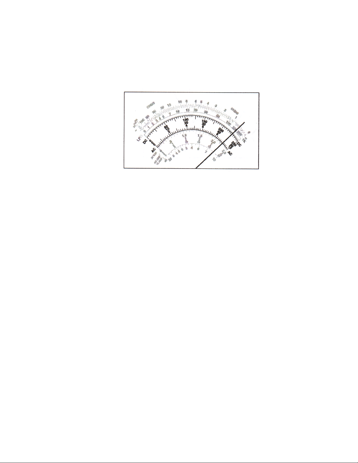
To measure a 9-volt battery, touch the meter probes to the battery termi-
nals. The needle moves across the voltage scale to the point, shown in
Figure 13.
Figure 13
Since the 10-volt range is selected, the reading will be taken on the
0 - 10 scale. Each increment on the scale represents .2 volts. Read the
pointer location on the scale between the 8 and the 10. It should indi-
cate approximately 9 volts.
Example 2
To measure a 20-volt battery:
a) Set the Range switch to the 25V position.
b) Touch the meter probes to the battery terminals.
c) Read the pointer on the 0 - 250 scale.
d) The pointer should indicate approximately 200 on the scale.
Since the range switch is set for 25V, divide the reading by 10
(200 ÷ 10 = 20).
Example 3
To measure a 280-volt circuit:
a) Set the Range switch to the 500V position.
b) Touch the meter probes to the circuit terminals.
c) Read the pointer on the 0 - 50 scale.
d) The pointer should indicate approximately 28 on the scale.
Since the range switch is set for 500V, multiply the reading by 10
(28 x 10 = 280).
17
Page 20
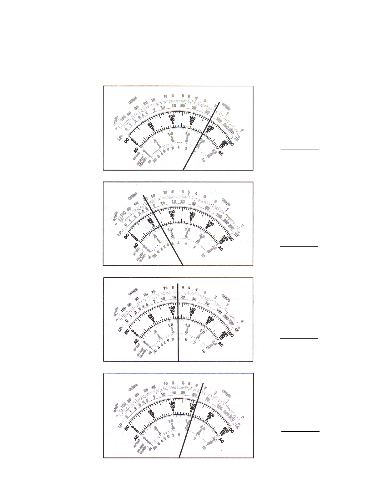
PRACTICE EXERCISE 2
READING THE VOLTAGE SCALES
Write the correct meter reading in the space provided by each illustra-
tion. The voltage ranges are shown below.
25V
1.
10V
2.
3.
100V
500V
4.
18
Page 21

— NOTES —
19
Page 22
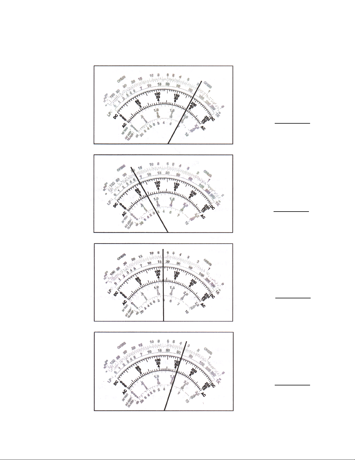
PRACTICE EXERCISE 2 ANSWERS
READING THE VOLTAGE SCALES
1.
2.
25V
19V
10V
2.8V
3.
4.
100V
45V
500V
315V
20
Page 23
MEASURING LINE VOLTAGE
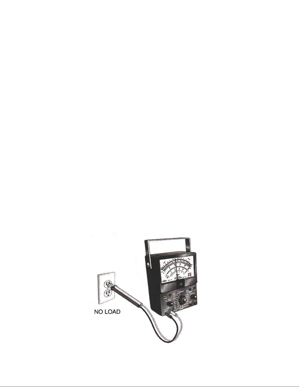
Line voltage is the voltage coming from the wall outlet. Line voltage can
be measured under no load (no appliance is connected or the appli-
ance is connected and turned off) or under a load (appliance is turned
on).
To measure the line voltage:
1. Attach the test probes to the meter.
• Plug the black probe into the outlet marked negative (–).
• Plug the red probe into the outlet marked positive (+).
2. Set the function switch to AC VOLTS.
IMPORTANT: Be sure the meter is set on the AC voltage scale and not
the Ohms scale.
3. Select a range that will include the voltage you are measuring.
• Higher than 125 volts AC if you are measuring 120 volts.
• Higher than 250 if you are measuring 220 volts.
To measure with no load:
1. Insert the test leads into the slots of the AC outlet (see Figure 14).
2. Read the meter and interpret the reading. The reading should be
between 115 and 120 volts.
Figure 14
21
Page 24
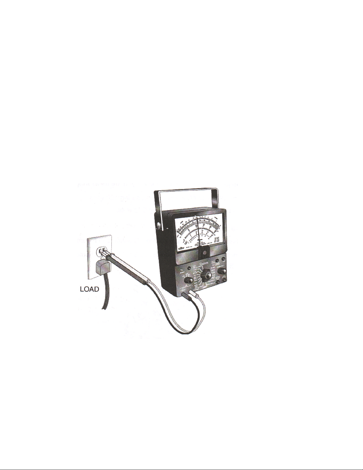
To measure with a load:
1. Plug the appliance into the receptacle and turn on the appliance (see
Figure 15).
2. Insert the meter probe tips into the empty receptacle.
3. Read the meter. Under load conditions, the reading may be slightly
less than under no load conditions.
IMPORTANT: Appliances with heavy drive motors, such as washers and
dishwashers, should also be tested at the moment of start. If the voltage
drops more than ten percent, (less than 108 volts), when the motor is
started, it means that there is a problem with the electrical supply (the
electricity coming into the receptacle). Mark this on the service invoice.
State that there is a problem with the circuit, and that the customer has
been informed.
22
Figure 15
Page 25

TESTING FOR GROUND AND POLARITY
A ground is a voltage reference point. Polarity is a check to make sure
that the outlet is wired correctly.
To test for proper grounding:
1. Test for line voltage (if there is no voltage you can not test for
ground).
2. Test for voltage between the short slot and the ground receptacle (the
round hole) (see Figure 16A).
• The receptacle has a long and a short slot. If the outlet has been
mounted correctly, the longer slot will be on the left (see Figure
16B).
• If there is line voltage between these two points it means the
receptacle is grounded.
IMPORTANT: Due to recent electrical code changes, you may begin to
see receptacles mounted upside down. This is done to make it easier to
put power cords into the outlet.
• If there is no round hole (ground receptacle), touch one of your
probes to the screw that fastens the cover plate to the outlet (see
Figure 16C ).
• No voltage indicates that the outlet is not grounded.
• To be grounded, the wire or tab must be attached to the screw.
CAUTION: IF THE OUTLET IS NOT GROUNDED, YOU WILL NOT
GET A READING. WRITE ON THE SERVICE ORDER: THE APPLI-
ANCE IS NOT GROUNDED AND THIS IS A DANGEROUS CONDI-
TION. THE CUSTOMER MUST CONTACT A QUALIFIED ELECTRI-
CIAN TO CORRECT THE SITUATION.
Figure 16
23
Page 26
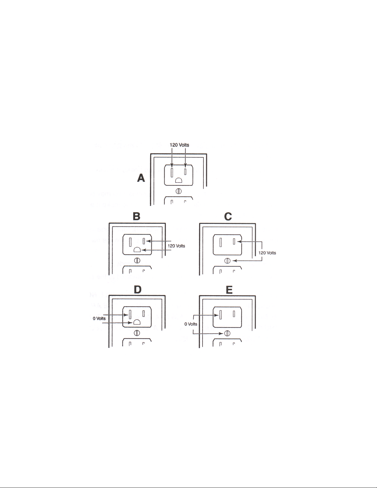
To test for polarity:
1. Test that there is line voltage between the long and short slots (120
volts) (see Figure 17A).
2. Test that there is line voltage between the short slot and the round
hole (ground receptacle) (see Figure 17B), or the center screw (120
volts) (see Figure 17C).
3. Test that there is NO VOLTAGE between the long slot and the ground
receptacle (see Figure 17D), or center screw (see Figure 17E).
Figure 17
CAUTION: IF THE OUTLET IS IMPROPERLY WIRED, THE THREE
TESTS, SHOWN ABOVE, WILL FAIL. A LICENSED ELECTRICIAN
MUST CORRECT THE PROBLEM.
REMEMBER: The short slot is HOT, the long slot is NOT.
24
Page 27
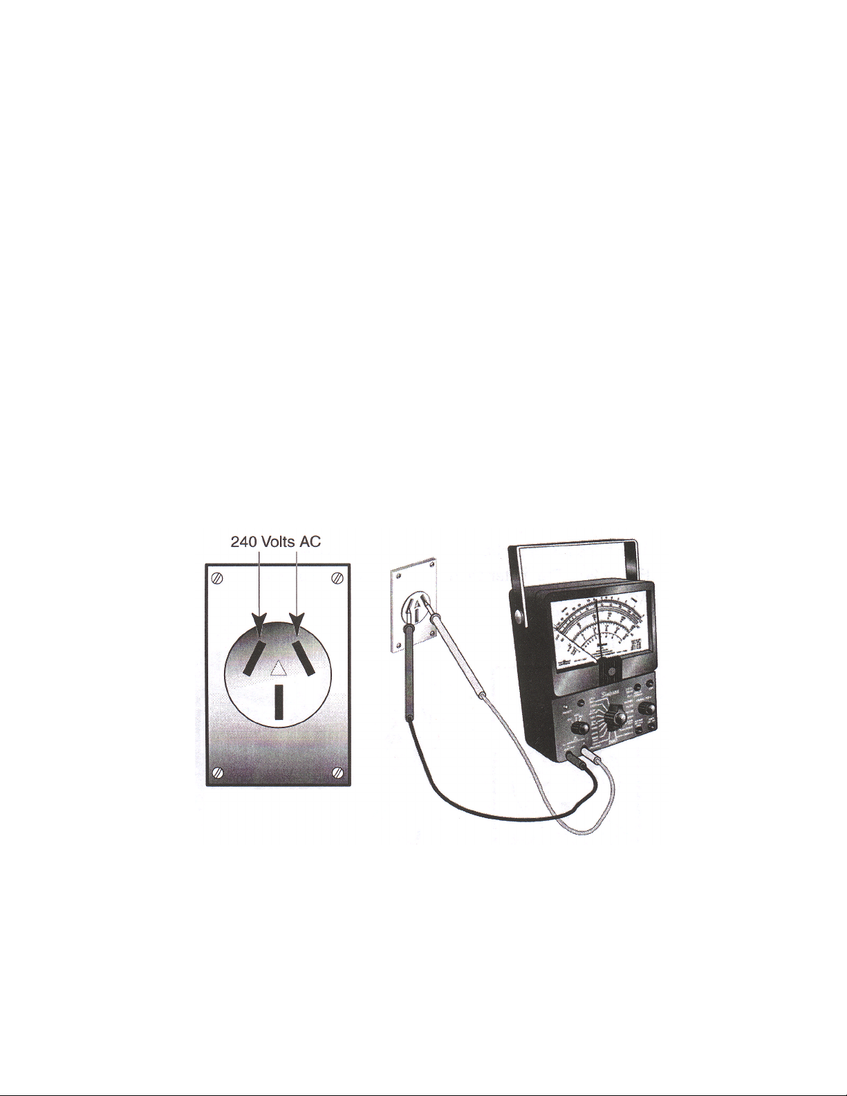
MEASURING 240 VOLTS AC (3-WIRE RECEPTACLE)
CAUTION: When measuring 240 volts AC, extreme care must be
taken not to touch the metal test probes.
To measure the 240 volt line:
1. Attach the test probes to the meter.
• Plug the black probe into the outlet marked negative (–).
• Plug the red probe into the outlet marked positive (+).
2. Set the function switch to AC VOLTS.
IMPORTANT: Be sure the meter is set on the AC voltage scale and not
the Ohm’s scale.
3. Select a range that will include the voltage you are measuring.
• Higher than 250 if you are measuring 240 volts.
4. Touch the meter probe tips to the indicated outlet openings (see
Figure 18). The meter should measure approximately 240 volts AC.
Figure 18
25
Page 28
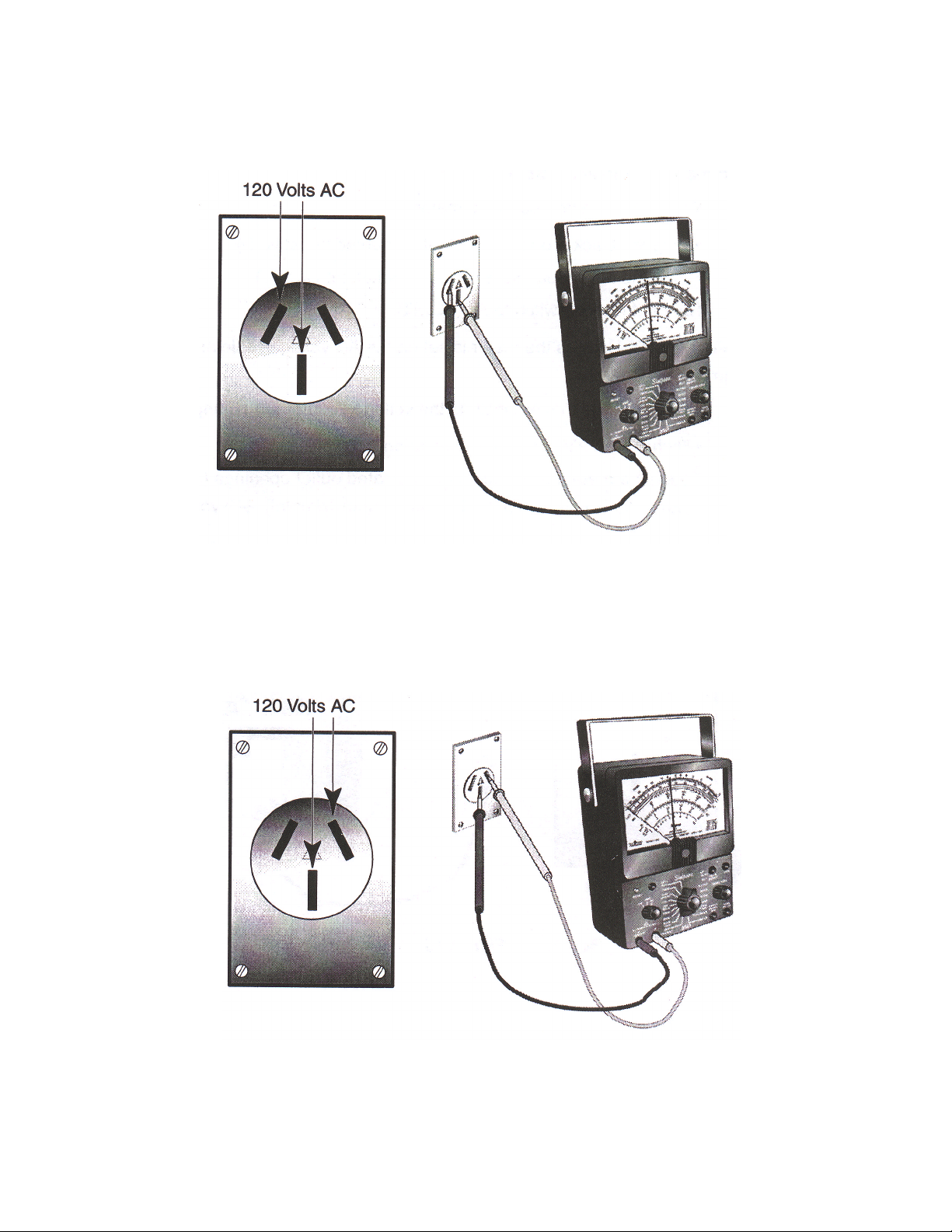
5. Touch the meter probe tips to the indicated outlet openings (see
Figure 19). The meter should measure approximately 120 volts AC.
Figure 19
6. Touch the meter probe tips to the indicated outlet openings (see
Figure 20). The meter should measure approximately 120 volts AC.
Figure 20
26
Page 29
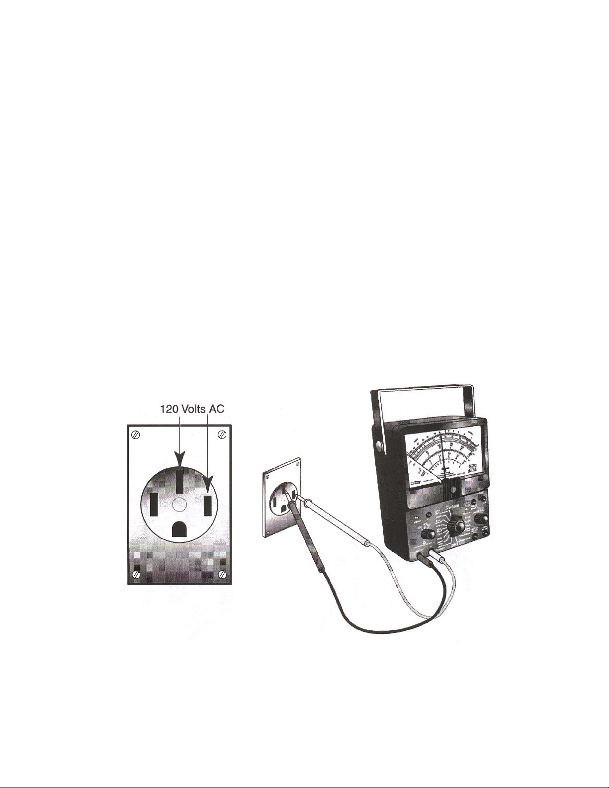
MEASURING 240 VOLTS AC (4-WIRE RECEPTACLE)
CAUTION: When measuring 240 volts AC, extreme care must be
taken not to touch the metal test probes.
To measure the 240 volt line:
1. Attach the test probes to the meter.
• Plug the black probe into the outlet marked negative (–).
• Plug the red probe into the outlet marked positive (+).
2. Set the function switch to AC VOLTS.
IMPORTANT: Be sure the meter is set on the AC voltage scale and not
the Ohm’s scale.
3. Select a range that will include the voltage you are measuring.
• Higher than 250 if you are measuring 240 volts.
4. Touch the meter probe tips to the indicated outlet openings (see
Figure 21). The meter should measure approximately 120 volts AC.
Figure 21
27
Page 30
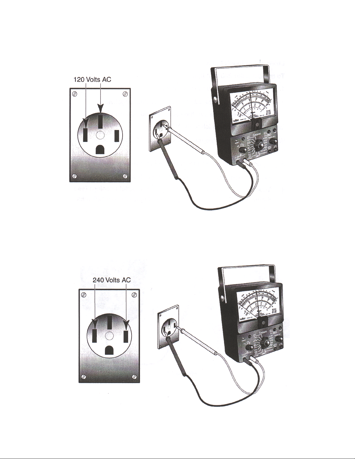
5. Touch the meter probe tips to the indicated outlet openings (see
Figure 22). The meter should measure approximately 120 volts AC.
Figure 22
6. Touch the meter probe tips to the indicated outlet openings (see
Figure 23). The meter should measure approximately 240 volts AC.
Figure 23
28
Page 31
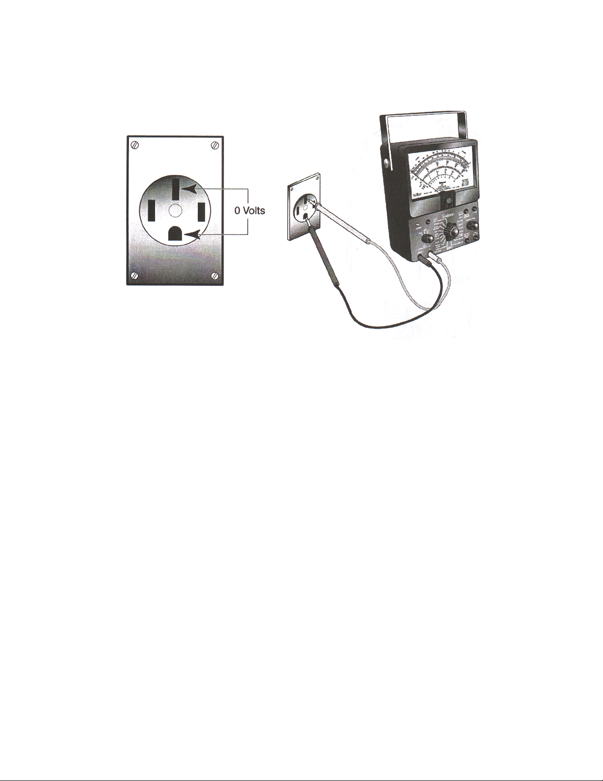
7. Touch the meter probe tips to the indicated outlet openings (see
Figure 24). The meter should measure 0 volts.
Figure 24
29
Page 32
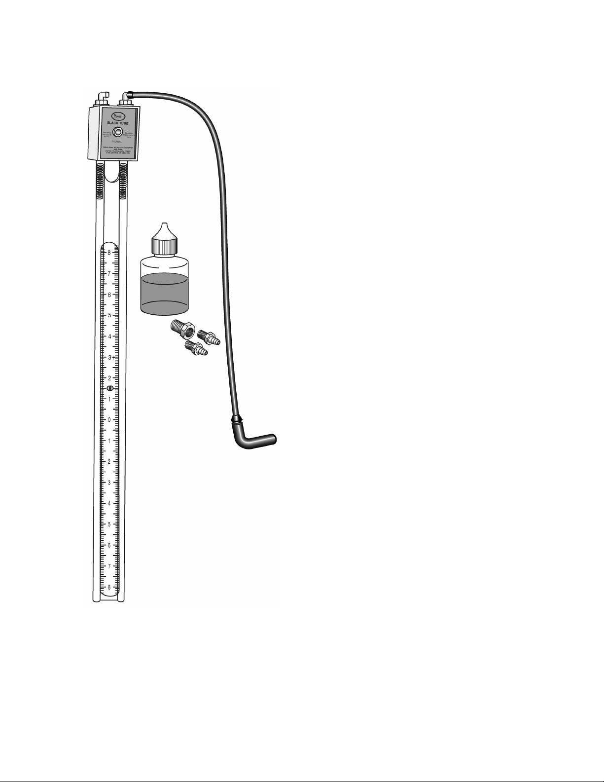
MANOMETER
When it becomes necessary to measure gas pressure,
there are two instruments available that you can use: a
manometer, like the one shown on this page, and a
magnehelic gauge (shown on page 32).
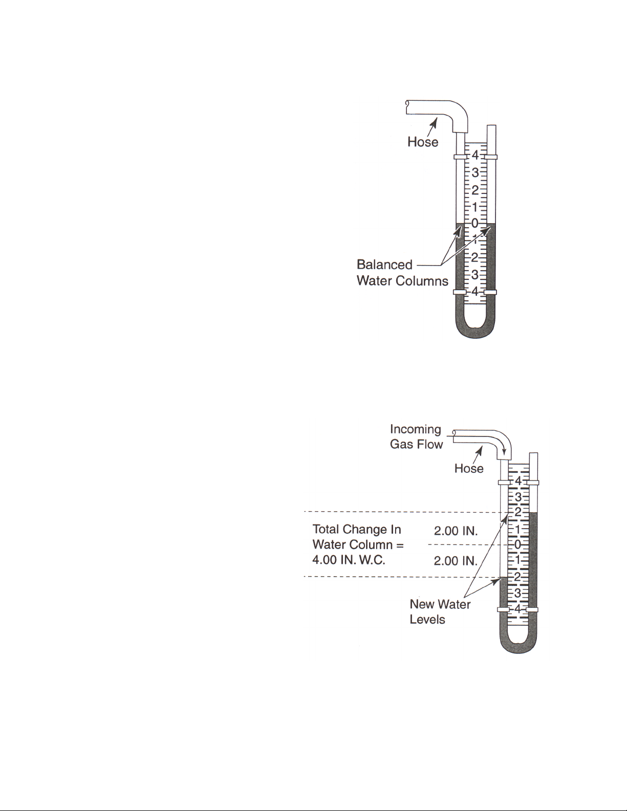
A manometer is basically a U-shaped tube with a scale, marked in
inches of water column. To prepare and use the manometer, use the
following steps:
30
Page 33
1. Check the appliance model/serial plate and note the gas pressure
rating.
2. Turn off the gas pressure to the range.
3. Prepare the manometer by filling the U-
shaped tube with water so that both
sides of the tube fill to the zero point
(see Figure 25). NOTE: Use a little food
coloring in the water to help make
reading the meter easier.
Figure 25
4. Connect the tubing that is supplied with the manometer over one end
of the manometer.
5. Remove a burner from the appliance and place the free end of the
tubing over the burner orifice.
6. Turn on the gas supply to the range.
7. Turn on the gas valve being
tested, and light at least one
other burner to serve as a
load.
8. Observe the movement of
the water in the manometer.
The gas pressure is read by
adding the water movement
in both legs of the tube, as
shown in Figure 26. It should
measure within the pressure
Figure 26
rating stated on the rating plate.
31
Page 34
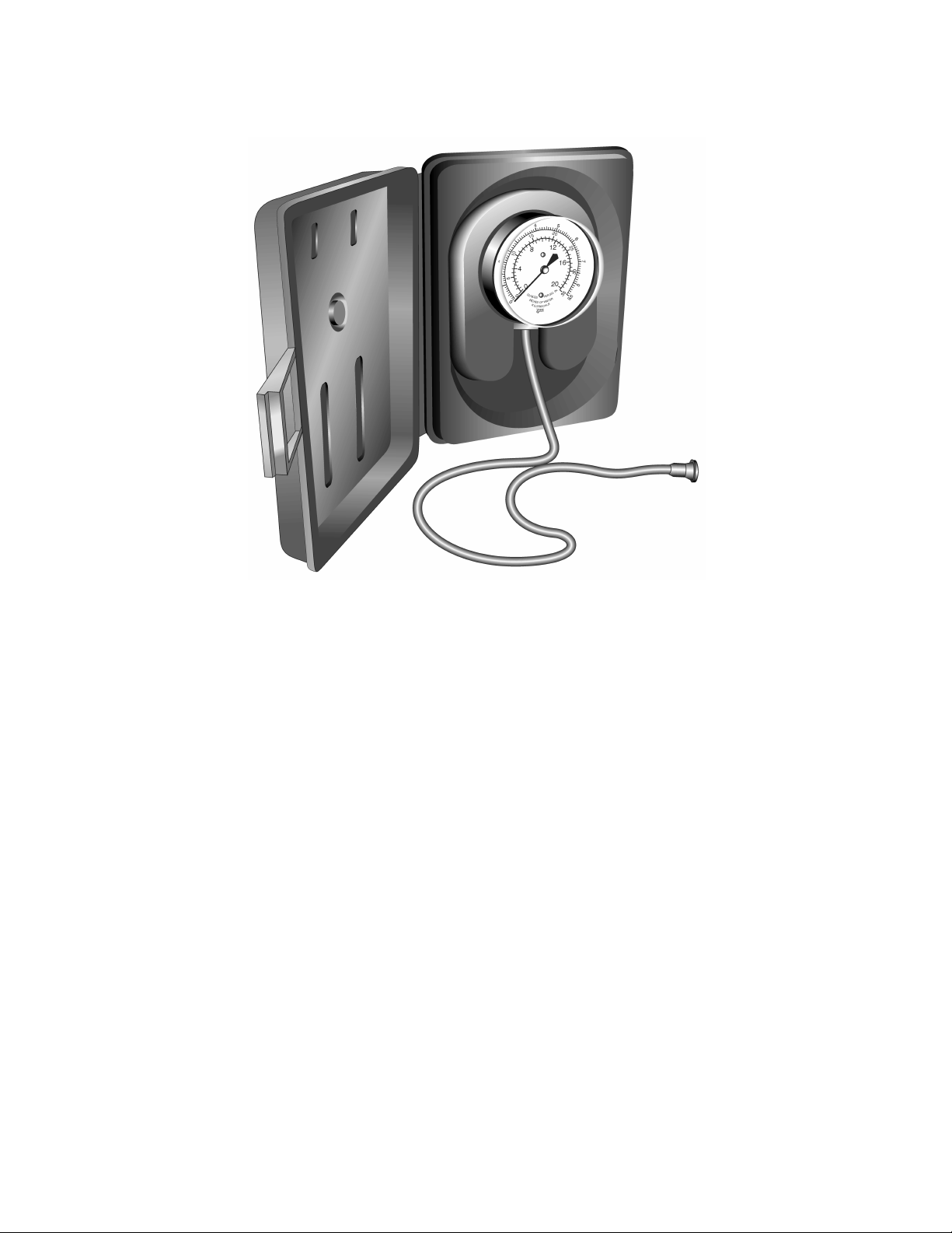
MAGNEHELIC GAUGE
The Magnehelic Gauge measures gas pressure. This type of gauge is
easier and faster to use than a manometer.
To use the gauge:
1. Check the appliance model/serial plate and note the gas pressure
rating.
2. Turn off the gas pressure to the range.
3. Remove a burner from the appliance and place the free end of the
tubing over the burner orifice.
4. Turn on the gas supply to the range.
5. Read the gas pressure directly from the scale of the gauge. It should
measure within the pressure rating stated on the rating plate. Some
gauges have numerous scales on the dial face. Read the water
column pressure scale when taking the measurement.
The Model G24507 Magnehelic Gauge is available from:
Marsh Bellafram, Inc.
1-800-727-5646
32
Page 35
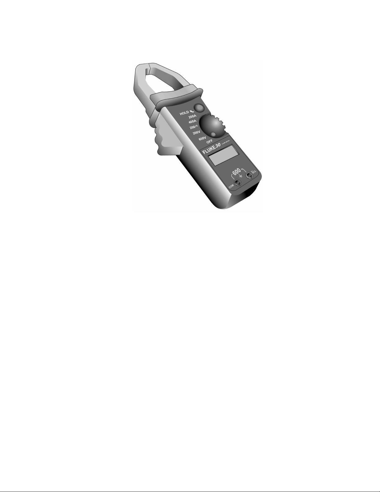
AMP CLAMP
The Fluke Model 30 Amp Clamp measures AC and DC current and
voltage. To use the meter, simply clamp it around the circuit under test,
and read the display for the appropriate measurement.
33
Page 36
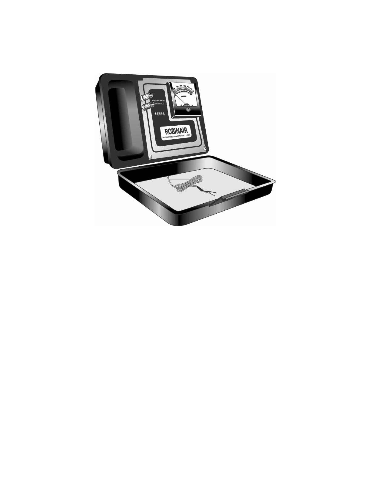
THERMOCOUPLE
TEMPERATURE TESTER
A Thermocouple Temperature Tester is helpful whenever it is necessary
to measure hot surface temperatures, or when calibrating gas or electric
ovens. The Tester is easy to use, and provides accurate temperature
measurements from –20˚F to 1350˚F. It is specially useful for measuring
temperature inside self-cleaning ranges, because of its high tempera-
ture range.
IMPORTANT: Do not “zero” the meter. It should always indicate the
ambient (surrounding) temperature.
To use the Thermocouple Temperature Tester, perform the following
steps:
1. Place the end of the thermocouple lead inside the area to be tested.
2. For greater accuracy, place the face of the meter in a horizontal
position.
34
Page 37

OPERATIONAL NOTES:
1. To avoid inaccurate readings, do not shorten the thermocouple lead,
or severely bend it.
2. Do not place the instrument on top of the range during testing. The
heat will make it difficult for the internal ambient temperature com-
pensator to function properly.
3. With both the meter movement and the lead stabilized at the same
ambient temperature, use the adjustment screw on the meter face to
set the meter at the ambient temperature. The ambient temperature
can be checked with an accurate glass thermometer.
4. If the instrument is suspected to be defective, check the lead and
meter. Replace the lead first. If the problem still exists, the meter
movement is faulty.
The Model 14855 Thermocouple Temperature Tester is manufactured
by:
Robinair Division
Sealed Power Corporation
Robinair Way
Montpelier, OH 43543
35
Page 38
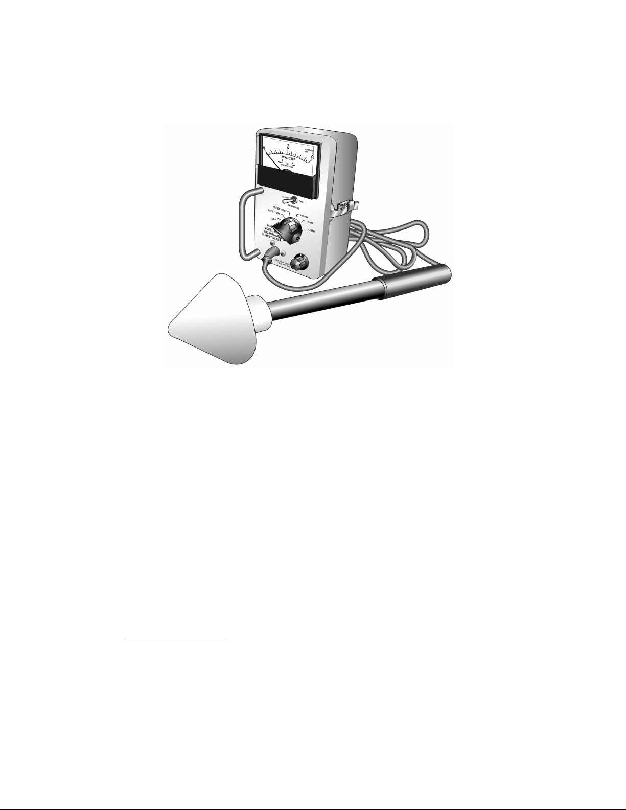
MICROWAVE SURVEY METER
Model HI1501
On every microwave oven service call, a check for microwave energy
emission must be performed. A properly operating door and seal assem-
bly will normally register small emissions, but they must be no greater
than 4 mw/cm2.
When checking for R.F. leakage, use an approved R.F. measuring
device to assure less than 4mw/cm2 emission at 5 cm distance with a
maximum scan rate of 2.5 cm/second, in compliance with U.S. Govern-
ment Department of Health, Education and Welfare 21CFR1030, Perfor-
mance Standard for Microwave Ovens.
IMPORTANT: The meter must not be used without the spacer cone
in place.
1. Before each use, both the battery and the probe should be tested.
To test the battery:
a) Turn the selector knob to the “Battery Test” position. The meter
should read above the green marker line on the meter. If this
reading is below the green line, replace the battery.
36
Page 39

To test the probe:
a) Turn the selector knob to “Probe Test.” The meter should read
between the green lines. If it does not, the probe is damaged and
should not be used. A defective probe cannot be replaced in the
field and should be returned to the factory for repair.
2. To operate the Microwave Survey Meter:
a) Turn the selection knob to the desired meter range.
b) Allow two (2) minutes for the instrument to stabilize.
NOTE: If the instrument has been stored in a very warm or
cold area, it should be allowed to stabilize at room tem-
perature with the selector switch ON until no zero drift is
observed.
c) Use the Zero Adjust knob and adjust the meter pointer to
true zero. The probe must be shielded or removed from
the vicinity of any R.F. field.
d) Keep the probe handle perpendicular, place the tip of the
cone against the surface to be measured, and the leakage
level will be accurately registered on the meter. The
spacer cone automatically gauges the detecting probe
5 cm from the test point. Always use the probe handle. DO
NOT PLACE YOUR HAND NEAR THE CONE END OF THE
PROBE.
e) The “Fast” position of the meter may be used to locate the
point of the highest leakage. Compliance readings should
be taken with the switch in the “Slow” position.
f) Zero the meter after each measurement. If there is a shift
in the meter zero, the measurement will not be accurate.
g) The selection knob should be turned to OFF when the
meter is not in use.
The Model Hl1501 Microwave Survey Meter is manufactured by:
Holiday Industries, Inc.
14825 Martin Drive
Eden Prarie, MN 55344
Phone: 612-934-4920
FAX: 612-934-3604
37
Page 40
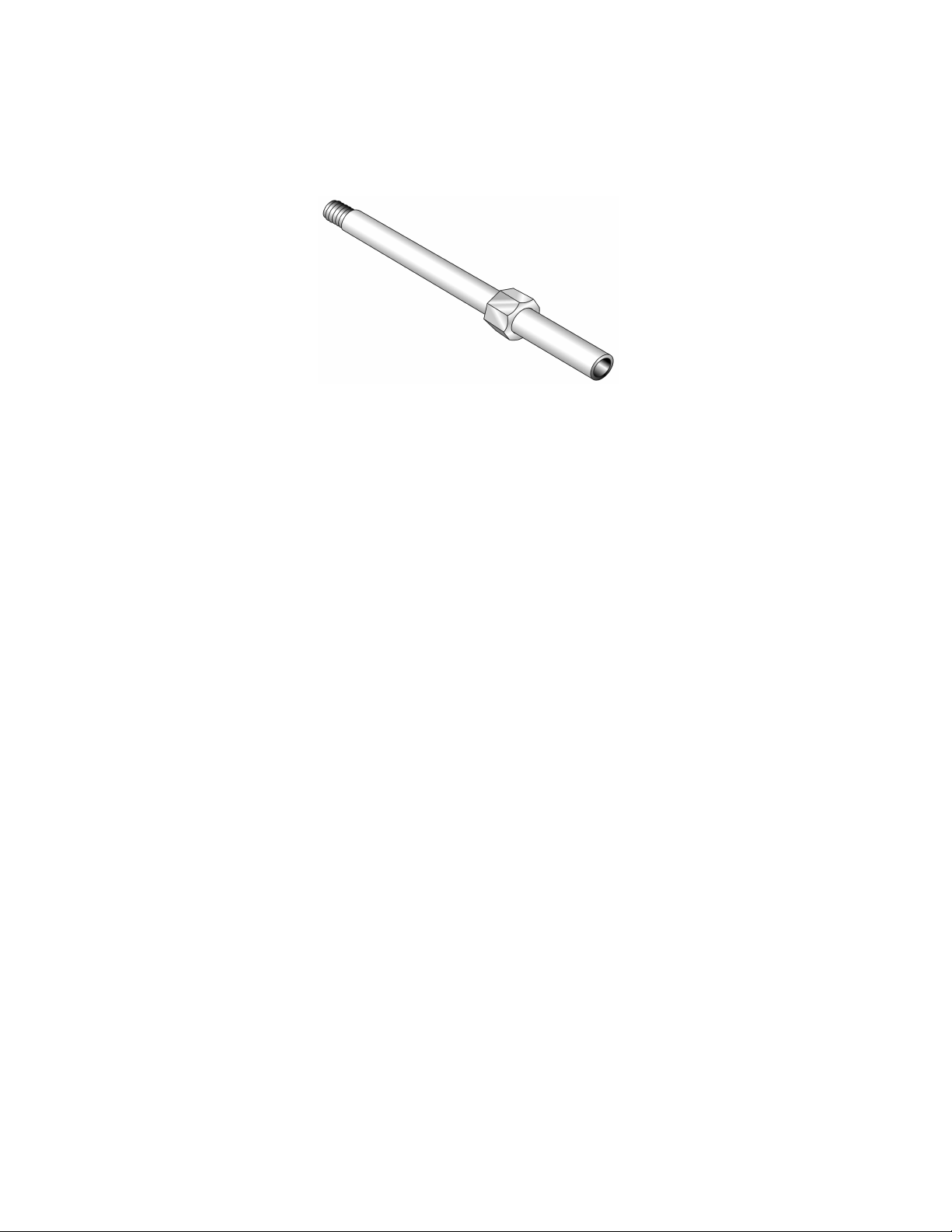
TAP TOOL
(For Sealed Gas Cooktops)
A tap tool (part #4372141) is required to perform a gas pressure check
on gas ranges with sealed burners. The tap tool is a small extension
that is used to lengthen the burner tube up to the cooktop area, so that
a hose can be connected from a gas pressure measuring device.
To connect the tap tool:
1. Remove the cooktop burner orifice from the burner to be tested.
2. Insert the tap tool in place of the burner orifice.
3. Perform the gas pressure test.
4. Remove the tap tool from the burner and reinstall the gas orifice.
38
Page 41
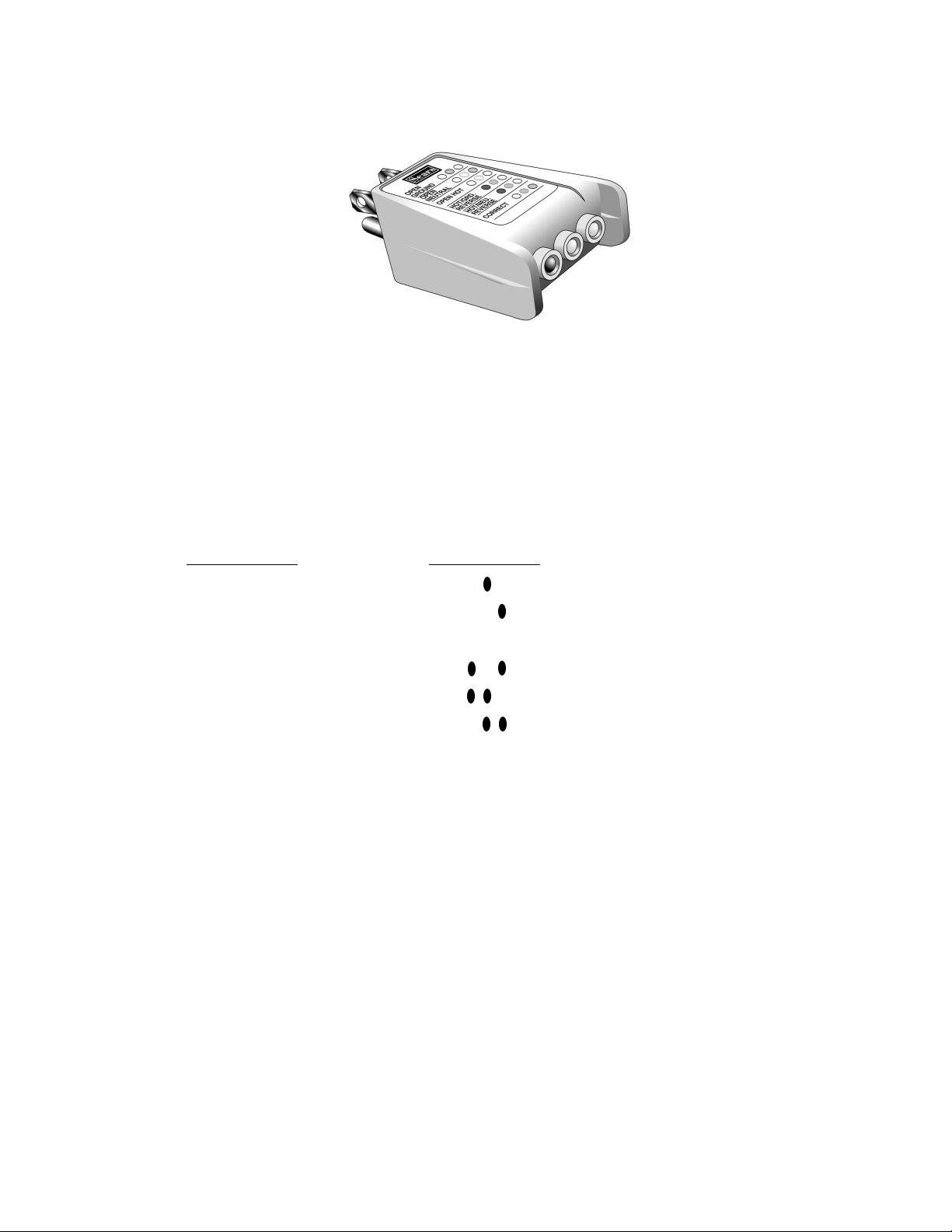
CIRCUIT TESTER
To assure proper operation of any appliance, the correct polarity and
grounding of its electrical outlet is necessary. One of the first checks on
appliances should be to verify that the wall outlet is wired correctly. A
circuit tester can easily and quickly verify that an appliance is connected
to a properly wired (120 VAC) wall outlet.
A series of lights within the tester will perform the following tests:
Test Function LED Reading
Open ground 0 0 0
Open Neutral 0 0 0
Open Hot 0 0 0
Hot/Ground Reversed 0 0 0
Hot/Neutral Reversed 0 0 0
Correct 0 0 0
39
Page 42
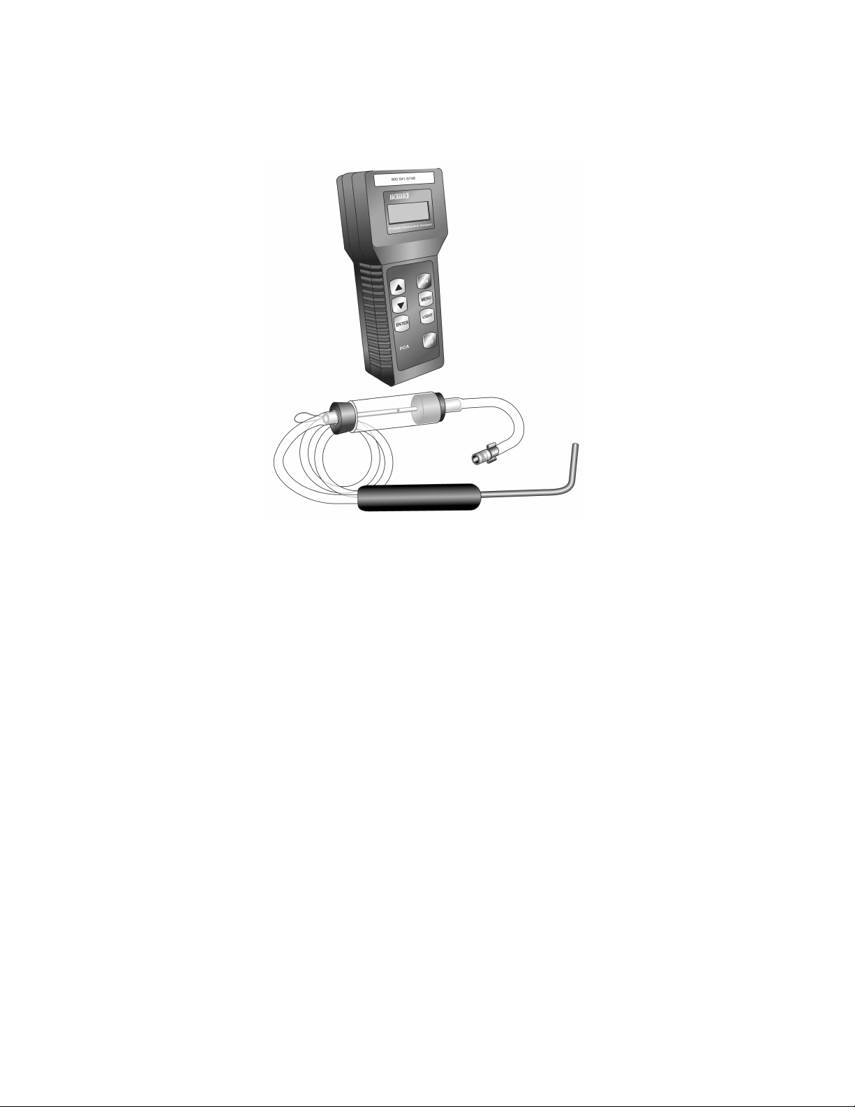
BACHARACH
CARBON MONOXIDE DETECTOR
To use the Bacharach Model PCA-12 Carbon Monoxide Detector:
1. Follow the instructions provided with the test equipment to prepare
the instrument. The unit will need a minute or so to warm up.
2. Let the oven operate for 7 minutes before taking measurements. Do
not position the meter near the oven during this period.
3. Insert the tester probe into the oven vent.
4. Press the RUN keypad.
5. Wait for the CO Air Free reading to stabilize.
6. Record the test results.
The Carbon Monoxide Detector is available by contacting the “Con-
sumer Assistance Center Safety Team” at: 1-800-541-5746.
40
Page 43
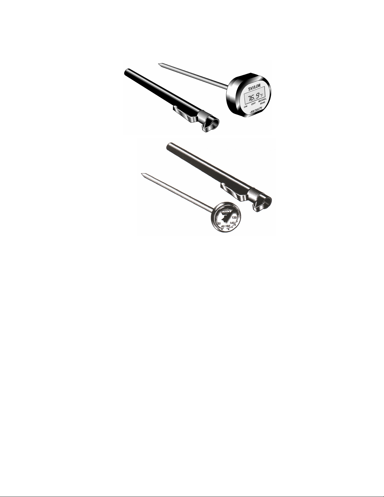
POCKET THERMOMETER
DIGITAL
ANALOG
The pocket thermometer is a handy tool for measuring temperature. For
example, it can measure freezer or refrigerator compartments, heated
water from microwave ovens, and exhaust temperatures from dryer
vents.
41
Page 44
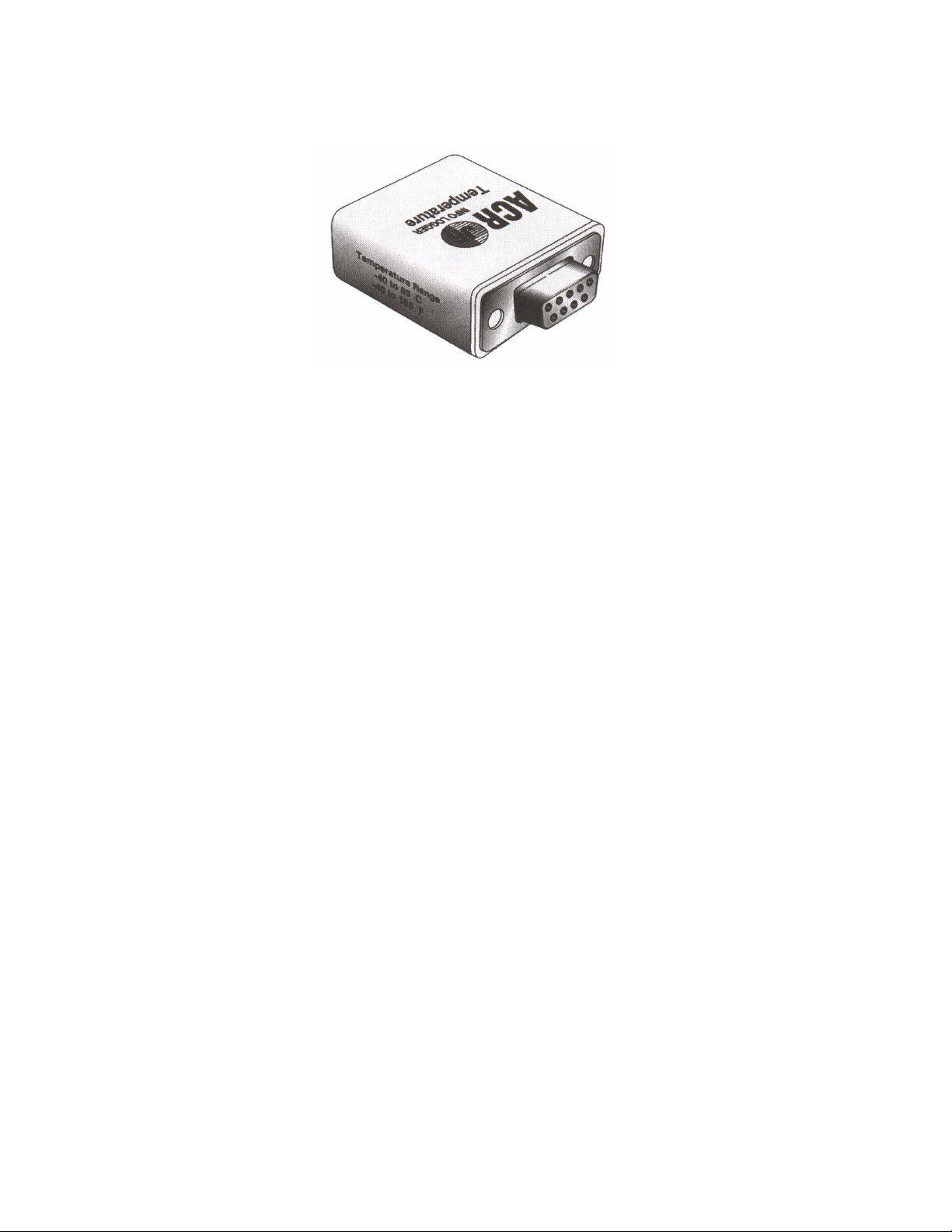
TEMPERATURE DATA LOGGER
The ACR Jr. Data Logger measures and stores changes in temperature.
The Logger is used with a computer to store and retrieve the data.
Simply place the ACR Jr. Data Logger wherever you would like to record
temperature changes. The logger will automatically read and store data
every 2 minutes. When you wish to retrieve the stored data, run the
ACR Jr. Graph software on your computer.
42
Page 45
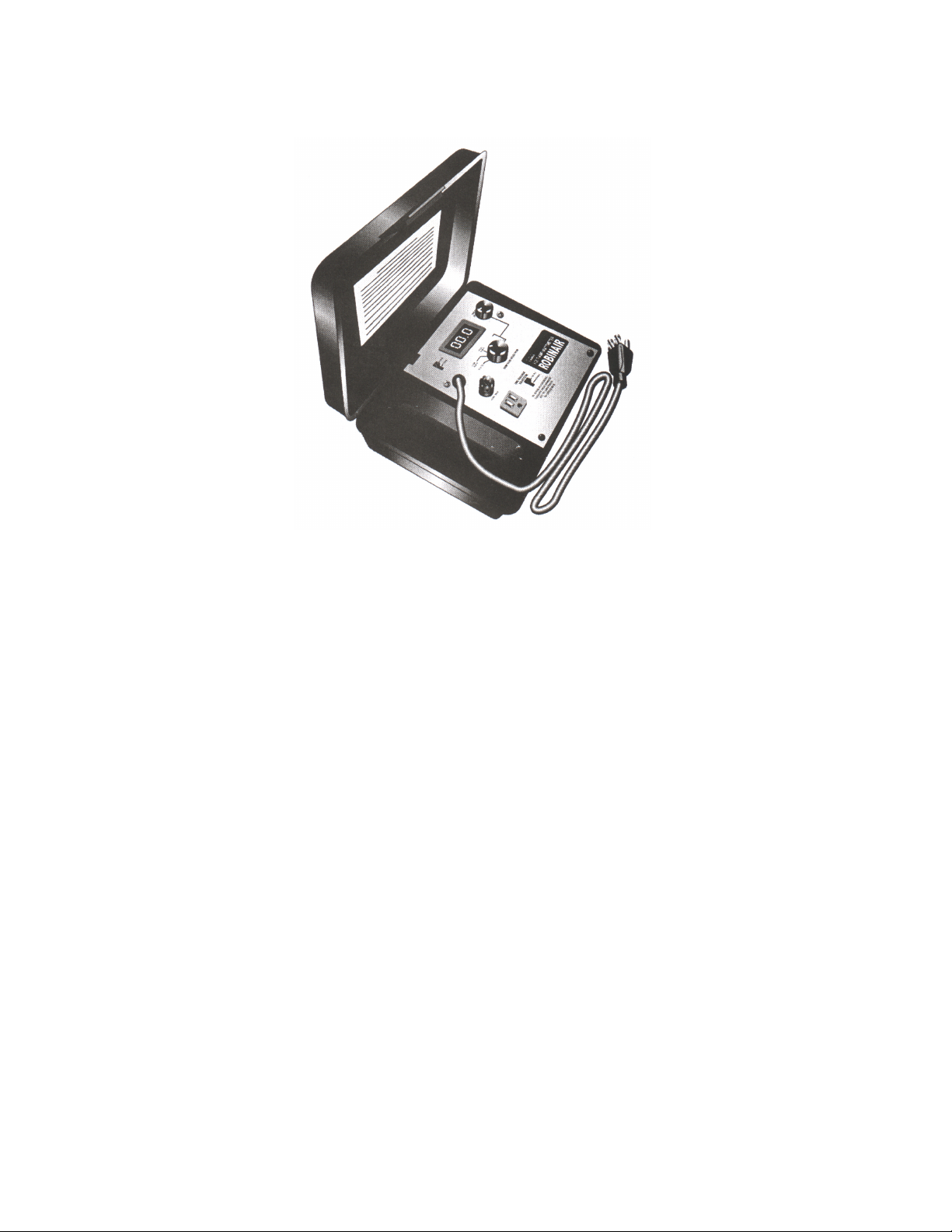
ROBINAIRE WATTMETER
The Robinaire Wattmeter, Model 14865, measures voltage, (120 and
240), amperage (up to 99.9 amps), and wattage (power consumption).
43
Page 46
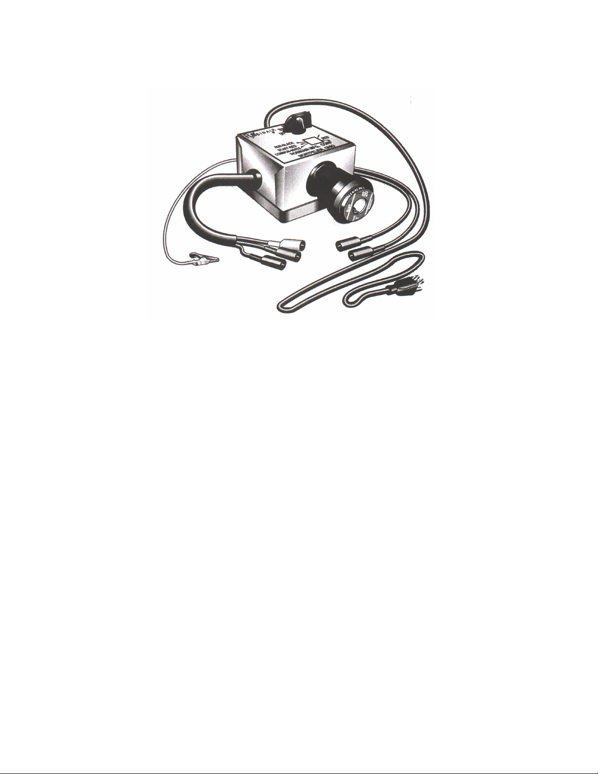
COMPRESSOR START TESTER
The Compressor Start Tester is used to check the compressor for open
grounds and open windings.
44
Page 47
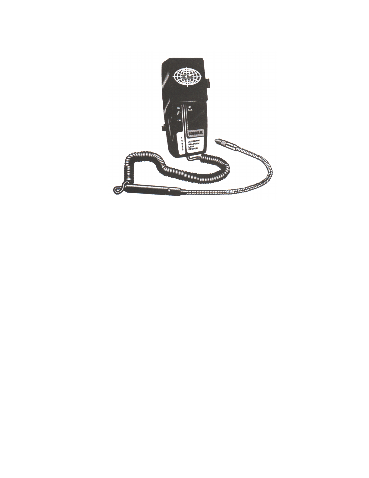
ELECTRONIC LEAK DETECTOR
The Electronic Leak Detector detects the presence of any refrigerant
escaping from the sealed system.
45
Page 48
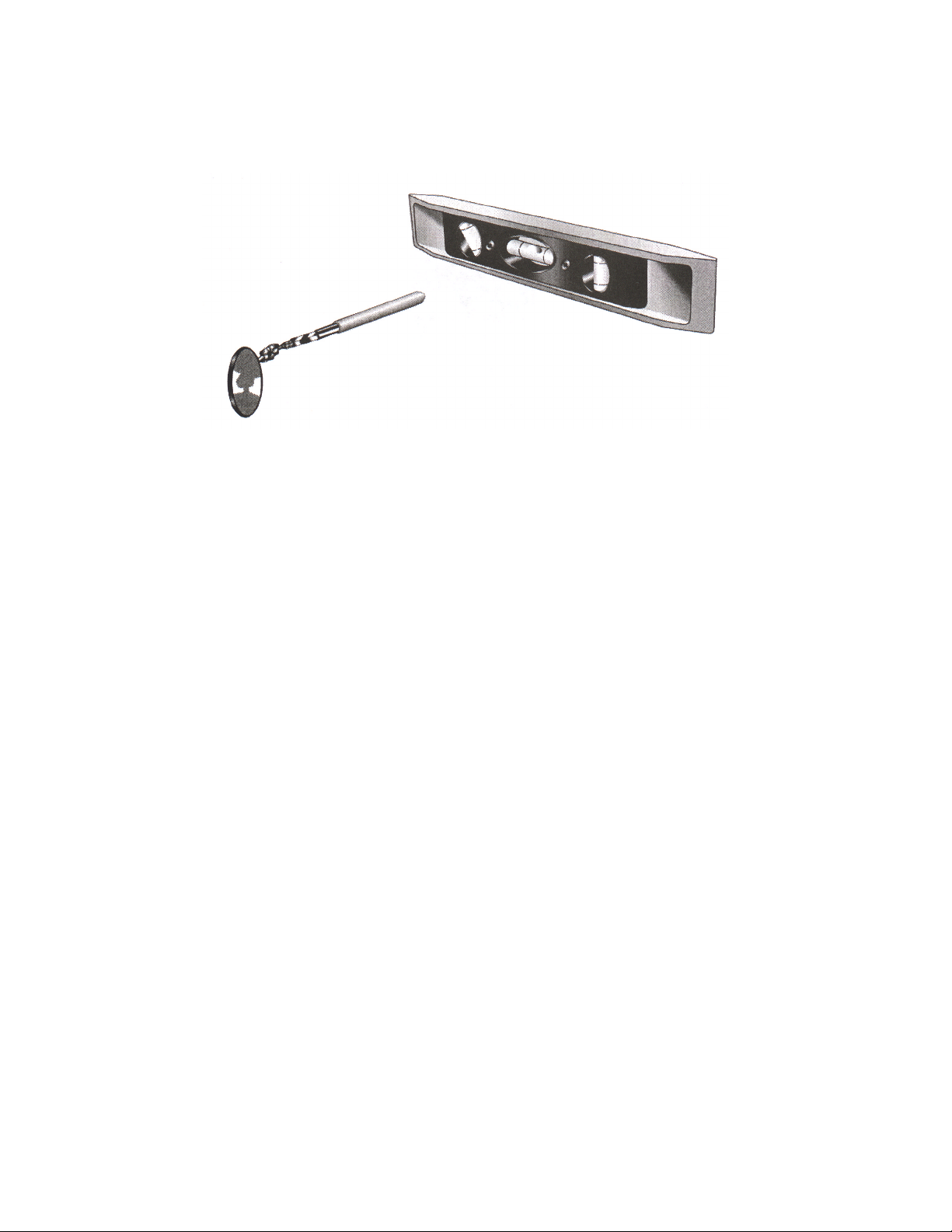
MACHINE LEVEL &
INSPECTION MIRROR
The Machine Level is used to level appliances after they are installed in
their mounting locations.
The Inspection Mirror is used to inspect around a brazed joint and
should be able to fit in small spaces.
46
Page 49

— NOTES —
47
Page 50

— NOTES —
48
Page 51

Page 52

CORPORATION
 Loading...