

Whirlpool ELPE 6260 IN INSTRUCTION FOR USE

41055007aGB.fm Page 18 Tuesday, June 27, 2006 6:07 PM
INSTRUCTIONS FOR USE
INSTALLATION ............................... 19
SAFEGUARDING THE ENVIRONMENT .....24
IMPORTANT NOTES....................................24
BEFORE USING THE OVEN.........................25
OVEN ACCESSORIES...................................26
CARE AND MAINTENANCE........................27
TROUBLESHOOTING GUIDE......................31
AFTER SALES SERVICE................................31
To make the most of your new oven, read the user’s instructions carefully and keep them on hand
for consultation in the future.
18
41055007aGB.fm Page 19 Tuesday, June 27, 2006 6:07 PM
INSTALLATION
Recommendations
Important: Disconnect the oven from the mains before carrying out any installation work or
servicing.
Installation must be carried out by a qualified electrician in accordance with the manufacturer’s
instructions and in compliance with local regulations.
Unpack the oven and make sure that the appliance has not been damaged during transport and that
the oven door closes properly.
centre.
After removing the oven from its packaging, leave it on the polystyrene base to prevent it from being
damaged.
When installing the oven it is advisable to wear protective gloves.
The oven is provided with two side handles
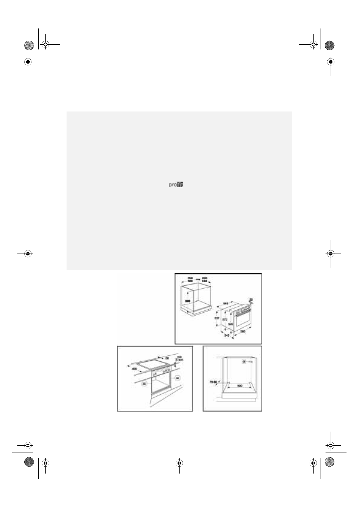
Preparing the housing unit
Built-under oven
Kitchen units in contact with the oven must be heat resistant (90 °C min).
Cut the kitchen unit and worktop to fit before installing the appliances. Carefully remove any shavings
or sawdust that could prevent the appliances from running properly.
The dimensions of the oven and unit are shown in figures 1-2-3.
To allow for proper ventilation, an opening should be left at the bottom of the housing unit. Pay
attention to the dimensions in fig. 3.
Leave a minimum clearance of 5 mm between the upper edge of the oven and the lower edge of the
worktop (fig. 2)
When installing, make sure that the sides of the oven do not touch the adjacent units.
If the kitchen unit is not securely fixed to the wall, it must be anchored with standard brackets (G)
available on the market, see fig. 3.
This clearance must never be obstructed.
If you are not sure contact the dealer or the nearest service
to facilitate installation (fig. 12).
(B)
Fig. 2
Fig. 1
Fig. 3
19
41055007aGB.fm Page 20 Tuesday, June 27, 2006 6:07 PM
Cooktop
Attention:
ceramic, stone, etc.) remember to ask After Sales Service for the fixing plates (fig. 6-8).
The cooktop must be fitted in a worktop with a minimum thickness of 20 mm and a maximum of
50 mm.
There must be nothing between the cooktop and the oven (e.g. cross rails, insulating material, etc.).
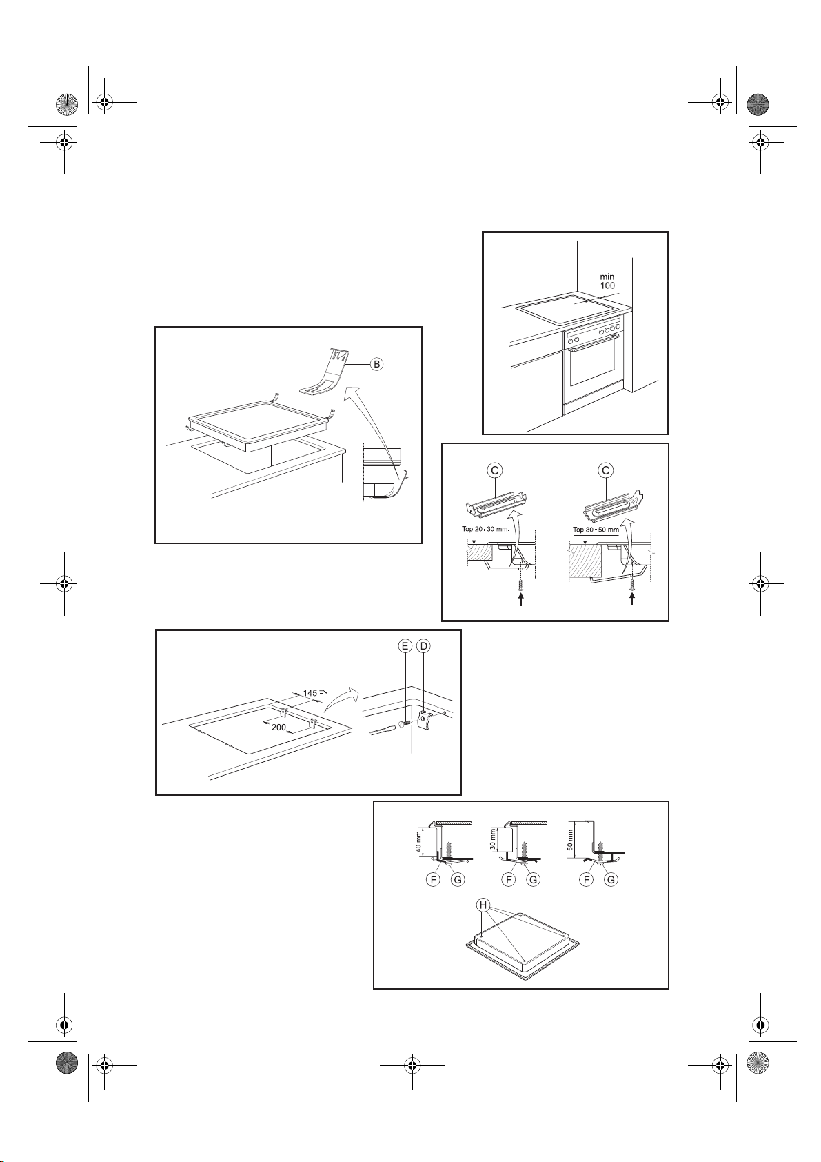
An adjacent column unit must be installed at least 100 mm from the edge of the cooktop (fig. 4).
Cut an opening in the worktop of the dimensions shown on the Product Description Sheet provided
with the worktop.
We recommend you seal the internal edges of the worktop with wood glue or silicone.
If not already in place, apply the supplied seal to the cooktop, after cleaning the adhesive surface
thoroughly.
Conventional electric cooktop
Important: Remove any protective film before installing the cooktop.
If the worktop is made of wood, use the spring clips and screws provided.
1.
2.
If the worktop is made of marble or other material (plastic, ceramics, stone, etc.),
cooktop must be secured with special brackets (C)
complete set from After Sales Service).
1.
2.
When installing the cooktop on a surface made of material other than wood (marble, plastic,
Insert the 4 spring clips (B) (fig. 5) in their guides on the bottom of the cooktop.
Fit the cooktop into the worktop.
6), Code 4819 310 18528, (available as a
(fig.
Fasten the brackets into the holes with the screws provided.
Fit the cooktop into the worktop.
Glass-ceramic cooktop
Important: Remove any protective film before installing the cooktop.
Make sure that that the opening in the worktop for the cooktop is cut according to the dimensions given
in the drawing on the Product Description Sheet. Pay attention to the tolerance range.
The cooktop should not be forced into the worktop. Forcing the glass-ceramic top may cause it to crack
(even at a later date)!
If the worktop is made of wood,
1.
Secure the spring clips (D) (fig. 7) with the screws provided (E) (fig. 7) as shown, paying attention to
the specified distances.
2.
Fit the cooktop into the worktop.
If the worktop is made of marble, plastic, ceramic, stone, etc.
with special brackets (F) (fig. 8), Code 4819 404 78697 available at After Sales Service.
1.
Fit the cooktop into the worktop.
2.
Place the 4 brackets (F) in position in accordance with the thickness of the worktop as shown i n fig. 8.
3.
Fasten the 4 screws (G) in the positions (H) (fig. 8).
use the spring clips and screws provided.
, the cooktop must be secured
the
20
41055007aGB.fm Page 21 Tuesday, June 27, 2006 6:07 PM
Fig. 4
Fig. 5
Fig. 6
Fig. 7
Fig. 8
21

41055007aGB.fm Page 22 Tuesday, June 27, 2006 6:07 PM
Electrical connection
Regulations require that the appliance be earthed.
Connection to the mains must be carried out by a qualified electrician in accordance with the
manufacturer’s instructions and in compliance with local regulations.
The installer is responsible for connecting appliances correctly to the mains and for observing the safety
regulations.
The oven power cable must be long enough to connect the built-in appliance to the mains.
Observance of safety directives requires that a multi pole switch with a minimum contact gap of 3mm
be used for the installation.
Do not use multiple plug adapters or extension leads.
After the oven has been installed, the electrical components must be inaccessible.
Connecting the oven to the power supply
Make sure that the voltage indicated on the rating plate is the same as the mains voltage.
The rating plate is on the front edge of the oven (visible when the door is open).
Remove the two fastening screws of the terminal box cover (if supplied) located on the bottom part of
the oven’s rear covering. Remove the cover to gain access to the terminal box and insert the power cable
(see table) through the opening located on the bottom of the oven. Connect the cable to the terminal
box and secure it to the cable fastener. Put the cover back on by inserting the two blades in the slots and
fasten it with the two screws.
Power supply cable table
N° of conductors Type of cable
1N+
2+
2N+
3N+
3+
~
~
~
~
~
H05 RR-F 3 X 1.5 mm²
H05 RR-F 3 X 1.5 mm²
H05 RR-F 4 X 2.5 mm²
H05 RR-F 5 X 1.5 mm²
H05 RR-F 4 X 2.5 mm²
22
 Loading...