

Whirlpool Electric Built-in Cooktop User Manual
v
id 01”
Home Appliances
Pike no 4454652
f
Part No. 4454652
Table de cuisson
hlectrique encastrbe
de 76,2 cm (30 po)
IMPORTANT :
Lire et conserver
ces instructions.
IMPORTANT :
lnstallateur
au proprietaire.
Proprihtaire
reference ulterieure.
Conserver
I’inspecteur local des installations electriques.
lnscrire les numeros de mod&e et de serie avant d’installer la
surface de cuisson.
Les deux numeros sont indiques sur la plaque signaletique des
numeros de modele et de serie, sit&e au fond de la table de
cuisson.
No de mod&e
: Remettre les instructions d’installation
: Conserver les instructions &installation pour
les instructions d’installation pour utilisation par
N” de serie
30” (76.2 cm) Electric
Built-in Cooktop
IMPORTANT:
Read and save these
instructions.
IMPORTANT:
Installer:
with the homeowner.
Homeowner:
Instructions for future reference.
Save
electrical inspector’s use.
Write down the model and serial numbers before installing cooktop.
Both numbers are on the model/serial rating
bottom of the cooktop.
Model #
Leave Installation Instructions
Keep Installation
Installation Instructions for local
Serial #
Before you start...
Proper installation is your responsibility.
Make sure you have everything for
correct installation. It is the responsibility
of the installer to comply with the
installation clearances specified on the
model/serial rating plate. The
model/serial ratina elate is found on the
bottom of the co$op.
p-width above cooktop
I
1 V (45.7 cm)
min. clearance
4th tiountertop
Do Not seal
caoktop to
countertop.
countertop depth
24” (61 cm) lower
cabinet depth
LA
-
Important:
Observe all governing codes and
ordinances.
Failure to meet governing codes and
ordinances could lead to fire or
electrical shock.
30” (76.2 cm) min. cabinet
.&.
wall at least 9”
(22.9 cm) below
countertop.
Cooktop installed over oven installation:
Only certain specified cooktop and oven
models are approved for cooktop over
oven installations. Cooktops approved for
this type of installation will have an
approval label located on the outside of
the burner box. If you do not find this label,
contact your dealer to confirm that
cooktop is approved. The Insert Sheet
included with your literature lists the
cooktop and oven combinations that are
appraoved for this type of installation.
Ovens approved for this type installation
will have an approval label located on top
of the oven. If you do not find this label,
contact your dealer or refer to the builtunder oven Installation Instructions.
30” (76.2 cm) min. base cabinet is
required. If cabinet has a drawer, a 4”
(10.2 cm) depth clearance from the
countertop to the top of the drawer (or
other obstruction) in base cabinet is
required.
Check location where cooktop will be
installed. The location should be away from
strong draft areas, such as windows, doors
and strong heating vents or fans. The
cooktop should be located for convenient
use in the kitchen.
When installing cooktop over a built-under
oven, Do Not fasten cooktop to
countertop with clamps. Cooktop then will
be easy to remove if servicing is ever
necessary.
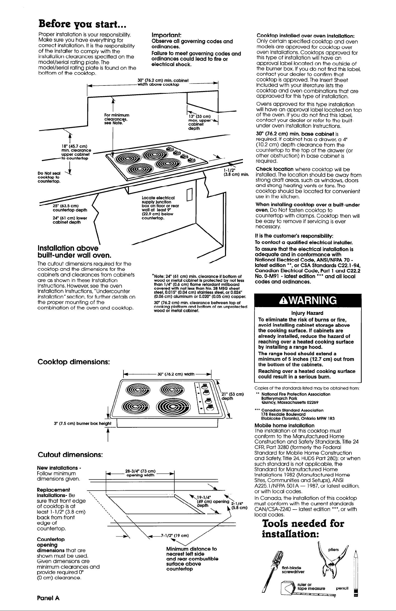
Installation above
built-under wall oven.
The cutout dimensions required for the
cooktop and the dimensions for the
cabinets and clearances from cabinets
are as shown in these Installation
Instructions. However, see the oven
Installation Instructions, “Undercounter
installation” section, for further details on
the proper mounting of the
combination of the oven and cooktop.
Coo ktop dimensions:
*Note: 24” (61 cm) min. clearance If bottom of
wood or metal cabinet is protected by not less
than l/4” (0.6 cm) flame retardant mlllboard
covered wlth not less than No. 28 MSG sheet
steel, 0.0 15” (0.04 cm) stainless steel, or 0.024”
(0.06 cm) aluminum or 0.020” (0.05 cm) copper.
30” (76.2 cm) min. clearance between top of
cooking platform and bottom of an unprotected
wood or metal cabinet.
30” (76.2 cm) width
4
It is the customer’s responsibility:
To contact a qualified electrical installer.
To assure that the electrical installation is
adequate and in conformance with
National Electrical Code, ANSI/NFPA 70 -
l
latest edition
*, or CSA Standards C22.1-94,
Canadian Electrical Code, Part 1 and C22.2
No. O-M91 - latest edition l ** and all local
codes and ordinances.
Injury Hazard
To eliminate the risk of burns or fire,
avoid installing cabinet storage above
the cooking surface. If cabinets are
already installed, reduce the hazard of
reaching over a heated cooking surface
by installing a range hood.
The range hood should extend a
minimum of 5 inches
(12.7
cm) out from
the bottom of the cabinets.
Reaching over a heated cooking surface
could result in a serious burn.
3” (7.5 cm) burner box helght
Cutout dimensions:
New installations Follow minimum
dimensions given.
Replacement
installations- Be “*
sure that front edge ‘\\,
of cooktop is at
least l-l /2” (3.8 cm)
back from front
edge of
countertop.
Countertop
opening
dimensions that are
shown must be used.
Given dimensions are
minimum clearances and
provide required 0”
(0 cm) clearance.
Copies of the standards listed may be obtained from:
l
* National Fire Protection Association
Batterymarch Park
Quincy, Massachusetts 02269
l
** Canadian Standard Association
178 Rexdale Boulevard
Etobicoke (Toronto), Ontario M9W 1 R3
Mobile home installation
The installation of this cooktop must
t
conform to the Manufactured Home
Construction and Safety Standards, Title 24
CFR, Part 3280 (formerly the Federal
Standard for Mobile Home Construction
and Safety, Title 24, HUDS Part 280); or when
such standard is not applicable, the
28-314” (73 cm)
opening width
I
Standard for Manufactured Home
Installations 1982 (Manufactured Home
Sites, Communities and Setups), ANSI
A225.1 /NFPA 501 A - 1987, or latest edition,
or with local codes.
In Canada, the installation of this cooktop
must conform with the current standards
CAN/CSA-Z240 - latest edition ***, or with
\
\
\
local codes.
Tools needed for
installation:
Minimum distance to
nearest left side
and rear combustible
surface above
countertop
Panel A
Electrical requirements
Electrical connection
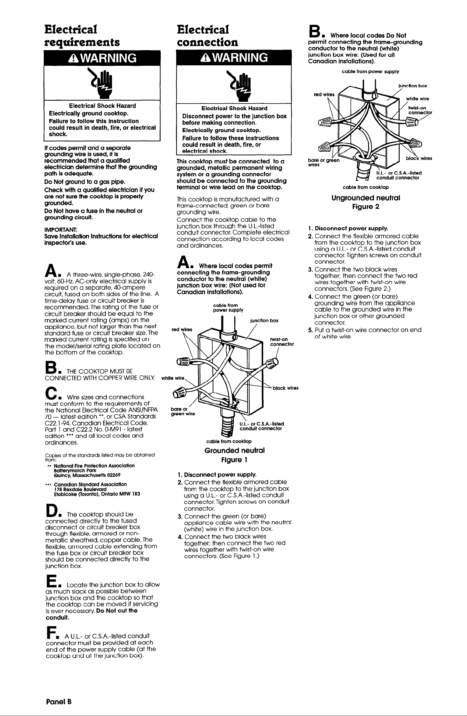
B
n
Where local codes Do Not
permit connecting the frame-grounding
conductor to the neutral (white)
junction box wire: (Used for all
Canadian installations).
cable from power supply
Electrical Shock Hazard
Electrically ground cooktop.
Failure to follow this instruction
could result in death, fire, or electrical
shock.
If codes permit and a separate
grounding wire is used, it is
recommended that a qualified
electrician determine that the grounding
path is adequate.
Do Not ground to a gas pipe.
Check with a qualified electrician if you
are not sure the cooktop is properly
grounded.
Do Not have a fuse in the neutral or
grounding circuit.
IMPORTANT:
Save Installation Instructions for electrical
inspector’s use.
n
A
volt, 60-Hz, AC-only electrical supply is
required on a separate, 40-ampere
circuit, fused on both sides of the line. A
time-delay fuse or circuit breaker is
recommended. The rating of the fuse or
circuit breaker should be equal to the
marked current rating (amps) on the
appliance, but not larger than the next
standard fuse or circuit breaker size. The
marked current rating is specified on
the model/serial rating plate located on
the bottom of the cooktop.
A three-wire, single-phase, 240-
Electrical Shock Hazard
Disconnect power to the junction box
before making connection.
Electrically ground cooktop.
Failure to follow these instructions
could result in death, fire, or
electrical shock.
L
This cooktop must be connected to a
grounded, metallic permanent wiring
system or a grounding connector
should be connected to the grounding
terminal or wire lead on the cooktop.
This cooktop is manufactured with a
frame-connected, green or bare
grounding wire.
Connect the cooktop cable to the
junction box through the U.L.-listed
conduit connector. Complete electrical
connection according to local codes
and ordinances.
n
A
connecting the frame-grounding
conductor to the neutral (white)
junction box wire: (Not used for
Canadian installations).
red wires AL 1
Where local codes permit
cable from
power supply
I I
junction box
/
K twist-on
connector
I
U‘.L.--or C.S.A.-listed
conduit connector
cable from cooktop
junction box
Ungrounded neutral
Figure 2
1. Disconnect power supply.
2. Connect the flexible armored cable
from the cooktop to the junction box
using a U.L.- or C.S.A.-listed conduit
connector. Tighten screws on conduit
connector.
3. Connect the two black wires
together; then connect the two red
wires together with twist-on wire
connectors. (See Figure 2.)
4. Connect the green (or bare)
grounding wire from the appliance
cable to the grounded wire in the
junction box or other grounded
connector.
5. Put a twist-on wire connector on end
of white wire.
n
B
CONNECTED WITH COPPER WIRE ONLY
C
must conform to the requirements of
the National Electrical Code ANSVNFPA
70 - latest edition **, or CSA Standards
C22.1-94, Canadian Electrical Code,
Pat-t 1 and C22.2 No. O-M91 - latest
edition
ordinances.
Copies of the standards listed may be obtained
from:
l
+ National Fire Protection Association
.*. Canadlan Standard Association
D
connected directly to the fused
disconnect or circuit breaker box
through flexible, armored or non-
metallic sheathed, copper cable. The
flexible, armored cable extending from
the fuse box or circuit breaker box
should be connected directly to the
junction box.
THE COOKTOP MUST BE
n
Wire sizes and connections
l
** and all local codes and
Batterymarch Park
Quincy. Massachusetts 02269
178 Rexdale Boulevard
Etobicoke (Toronto), Ontario M9W 1 R3
n
The cooktop should be
ud
white wire,
bare or ’
green wire
II //\\
U.;- or C.S.A.-listed
conduit connector
cable from cooktop
Grounded neutral
Figure 1
1. Disconnect power supply.
2. Connect the flexible armored cable
from the cooktop to the junction box
using a U-L.- or C.S.A.-listed conduit
connector. Tighten screws on conduit
connector.
3. Connect the green (or bare)
appliance cable wire with the neutral
(white) wire in the junction box.
4. Connect the two black wires
together; then connect the two red
wires together with twist-on wire
connectors. (See Figure 1.)
“,
L.
black wires
n
t
as much slack as possible between
junction box and the cooktop so that
the cooktop can be moved if servicing
is ever necessary. Do Not cut the
conduit.
connector must be provided at each
end of the power supply cable (at the
cooktop and at the junction box).
Locate the junction box to allow
n
A U.L.- or C.S.A.-listed conduit
Panel 6
 Loading...