

,...
(,R-;g ,_ r ~~,J-y? T\
Important:
Read and save
these instructions.
IMPORTANT:
Installer:
Homeowner:
Save lnstaliation Instructions for local electrical
Leave lnstallatlon Instructions
with the homeowner.
Keep Installation Instructions
for future reference.
inspectols use.
30” Electric
Built-in
Ceramic
Cooktop
Part No. 3147386
Rev.
B
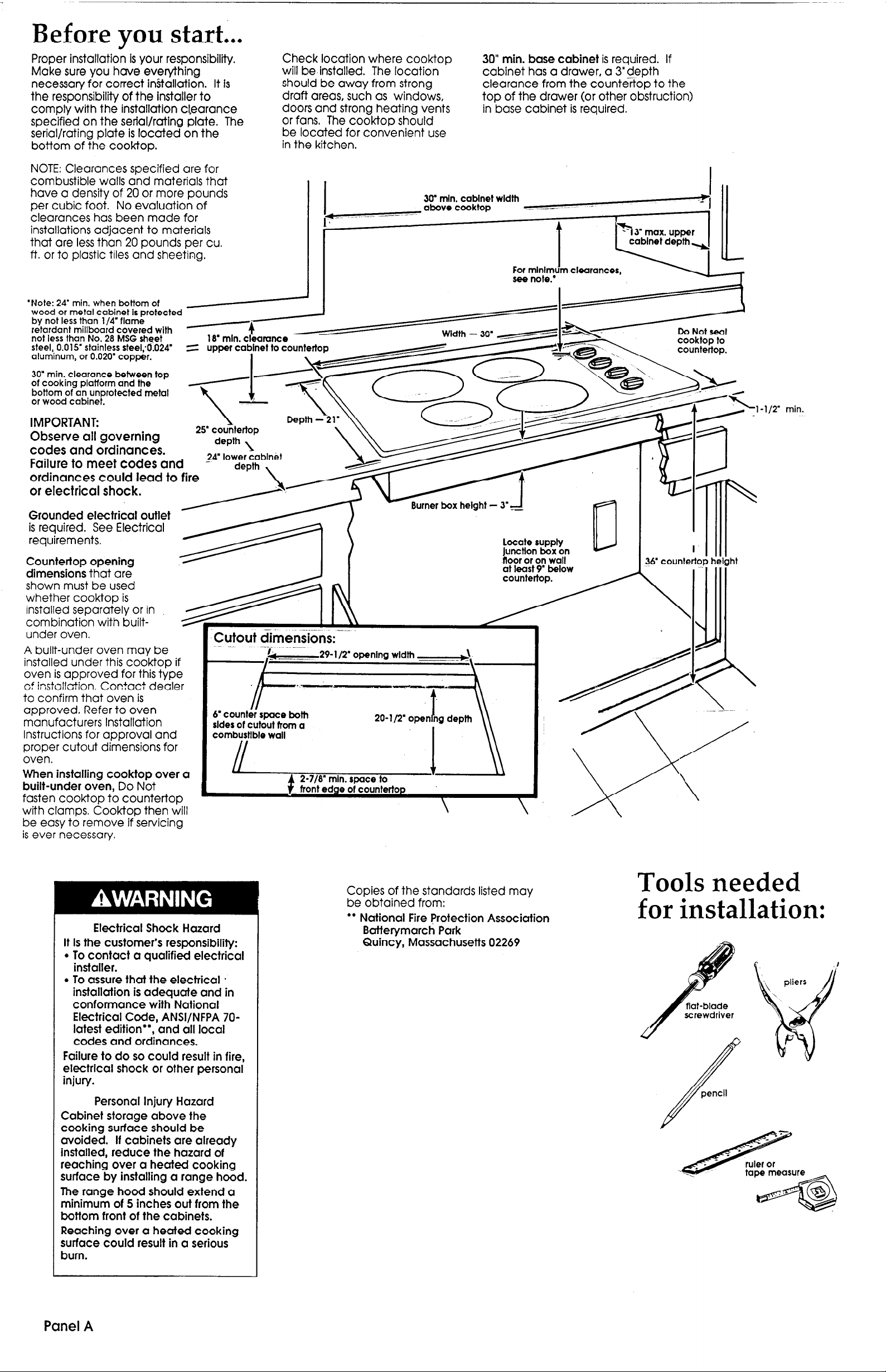
Before you start...
Proper installation 1s your responsibility.
Make sure you have everything
necessary for correct in.Stallation. It is
the responsibility of the installer to
comply with the installation cl,earance
specified on the serial/rating plate. The
serial/rating plate is located on the
bottom of the cooktop.
NOTE: Clearances specified are for
combustible walls and materials that
have a density of 20 or more pounds
per cubic foot. No evaluation of
clearances has been made for
installations adjacent to materials
that are less than 20 pounds per cu.
ft. or to plastic tiles and sheeting.
*Note: 24’ min. when bottom of
wood or metal cabinet is protected
by not less than 1/4’flame
retardant millboard covered with
not less than No. 28 MSG sheet 18’ min. clbarance
steel,. 0.015’ stainless steel;6.024
aluminum, or 0.020’ copper.
30” min. clearance between top
of cooking platform and the
bottom of an unprotected metal
or wood cabinet.
-4
=
upper cabinet to c
I
IMPORTANT:
Observe all governing
codes and ordinances.
Failure to meet codes and
depth l
pIoH
* * ‘.
;;t;DFer LLL
Check location where cooktop 30” min. base cabinet is required. if
will be installed. The location
should be away from strong
draft areas, such as windows,
doors and strong heating vents
or fans, The cooktop should
be located for convenient use
in the kitchen,
30’ min. cabinet width
I
r7’-- ~---~-
_ .-- --
obove cooktop
cabinet has a drawer, a 3” depth
clearance from the countertop to the
top of the drawer (or other obstruction)
in base cabinet is required.
.- -__
1
Jx
,112” min.
t
~~~~~~~~er~xheight-3*~ n 1 1 ))I) ’
locate supply
Countertop opening
dimensions that are
shown must be used
whether cooktop is
installed separately or in
combination with built- +
under oven.
A built-under oven may be
installed under this cooktop if
oven is approved for this type
of installation. Contact dealer
to confirm that oven is
approved. Refer to oven
manufacturers Installation
Instructions for approval and
proper cutout dimensions for
oven.
When installing cooktop over a
built-under oven, Do Not
fasten cooktop to countertop
with clamps. Cook-top then will
be easy to remove if servicing
is ever necessary.
Cutout dimensions:
I.
- ---~
6’ counter space both
sldes of cutout from a
combustible wall
29-l/2’ openlng width
.-
2-7/8’ min. space to
front edge of countertop
t
-\
-A
20-l/2’ open ng depth
t
I
\
junctton box on
at lea!
countt,,vP
?6’ countertop height
Electrical Shock Hazard
it is the customer’s responsibility:
. To contact a qualified electrical
installer.
. To assure that the electrical .
installation is adequate and in
conformance with National
Electrical Code, ANSi/NFPA 70latest edition**, and all local
codes and ordinances.
Failure to do so could result in fire,
electrical shock or other personal
injury.
Personal Injury Hazard
Cabinet storage above the
cooking surface should be
avoided. if cabinets are already
installed, reduce the hazard of
reaching over a heated cooking
surface by installing a range hood.
The range hood should extend a
minimum of 5 inches out from the
bottom front of the cabinets.
Reaching over a heated cooking
surface could result in a serious
bum.
Copies of the standards listed may
be obtained from:
l
* National Fire Protection Association
Batterymarch Park
Quincy, Massachusetts 02269
Tools needed
for installation:
Panel A

--
Electrical
requirements
IMPORTANT:
Save Installation Instructions for
electrical
l
Electrical ground is required on
this appliance.
l
If cold water pipe is interrupted
by plastic, non-metallic gaskets
or other insulating materials, Do
Not use for grounding.
l
Check with a qualified
electrician if you are in doubt as
to whether the appliance is
properly grounded.
l
Do Not have a fuse in the neutral
or grounding circuit. A fuse in the
neutral or grounding circuit could
result in electrical shock.
Failure to follow these instructions
could result in an electrical shock
or other personal injury.
If codes permit and a separate grounding
wire is used, it is recommended that a
qualified electrician determine that the
grounding path is adequate.
A
A three-wire, single phase, 24C-volt,
60-Hz, AC only electrical supply is
required on a separate, 4Gampere
circuit, fused on both sides of the
line. (A time-delay fuse or circuit
breaker is recommended.) The fuse
size must not exceed the circuit
rating of the appliance specified on
the serial/rating plate located on
the bottom of the cooktop.
It is the personal responsibility and
obligation of the customer to
contact a qualified electrician to
assure that the electrical installation is
adequate and in conformance with
National Electrical Code, ANSI/NFPA
70-latest edition*, and all local codes
and ordinances.
inspector’s use.
Electrical Shock Hazard
n
Electrical
connection
Electrical Shock Hazard
l
Electrical ground is required on
this appliance.
l
This appliance must be
connected to a grounded,
permanent wiring system or a
grounding connector should be
connected to the grounding
terminal or wire lead on the
appliance.
l
Disconnect power to the
junction box.
l
Do Not connect to the
electrical supply until
appliance is permanently
grounded.
Failure to do so could result in
electrical shock, serious injury, or
death.
This appliance is manufactured with a
frame-connected, green or bare,
grounding wire.
Connect the appliance cable to the
junction box through the U.L.-listed
conduit connector. Complete
electrical connection according to
local codes and ordinances,
Where local codes permit
connecting the framegrounding conductor to the
neutral (white) junction box
wire:
Cable from
power supply
Where local codes
Do Not
permit connecting the frame-
grounding conductor to the
neutral (white) junction box
wire:
Cable from
Junction box , ,
green wire
(ungrounded neutral)
power supply
White wire
/I
L
A conduit connec
Cable from cooktop
Cap
Figure 2
1. Disconnect the power supply.
2. Connect the two black wires; then
connect the two red wires. (See
Figure 2.1
3. Connect the green or bare
grounding wire from the appliance
cable to a grounded wire in the
junction box or to a grounded,
copper, cold water pipe.”
4. Do Not ground to a gas supply pipe
or hot water pipe. Do Not connect to
electrical supply until appliance is
permanently grounded.
(See Figure 3.1
l
* Grounded, cold water pipe must have
metal continuity to electrical ground and
not be Interrupted by plastic, rubber, or
other electrlcal insulating connectors such
as hoses, fittings, washers or gaskets
(including water meter or pump). Any
electrical insulating connector should be
jumped as shown with a length of
copper wire securely clamped to bare
metal at both ends.
No;4
:tor
B
THE kOOKTOP MUST BE CONNECTED
WITH COPPER WIRE ONLY.
@.
Wire sizes and connections must
conform to the requirements of the
National Electrical Code, ANSI/NFPA 70
-
latest edition*, and all local codes
and ordinances.
Copies of the standards listed may be
obtained from:
l
National Fire Protection Association
Batterymarch Park
Quincy, Massachusetts 02269
D
The
:ppliance should be connected
directly to the fused disconnect (or
circuit breaker) through flexible,
armored or non-metallic sheathed,
copper cable. The flexible, armored
cable extending from the appliance
should be connected directly to the
junction box. Allow two or three feet
of slack in the line so that the
appliance can be moved if servicing
Is ever necessary.
A U.L.-listed conduit connector must
be provided at each end of the power
supply cable (at the appliance and at
the junction box). Wire sizes (COPPER
WIRE ONLY) and connections must
conform with the rating of the
appliance (40 amperes).
Cable from
cooktop
(grounded neutral)
Figure 1
1. Disconnect the power supply.
2. Connect the green (or bare)
appliance cable wire with the neutral
wire in the junction box.
3. Connect the two black wires; then
connect the two red wires. Gee
Figure 1.1
Tlghten nuts flrmlv.
Grounded cold water
pipe (remove point, etc.)
Figure 3
Bumps on
grounding clamp
must contact pipe.
copper
Clamps
Panel B

Now start...
.With cooktop in kitchen.
Property Damage ’
lift entire cooktop up from cutout
when repositioning cooktop in
countertop opening.
Failure to do so could scratch
countertop.
~_ -
t9
+clamp
4.
Make the electrical connection.
(See Electrical requirements
and Electrical connection sections,
Panel 8, for details j
B
5
Turn on the power supply.
/III
1
Insert the cooktop into the
countertop cutout. Center the
cooktop in the cutout. Check that
the front of the cook-top is parallel to
the front edge of the countertop.
Check that all required clearances
are met. If cooktop is not properly
positioned, lift the entire cooktop
out of opening to make adjustments.
II ”
1....1
countertop
L.
Insert one clamp tab through each
slot located on sides of the
burner box.
cooktop
burier box
Personal Injury Hazard
Do Not touch cooktop heating
elements; they may be hot.
Touching a heated cooking
surface could result in a serious
burn.
6.
Push in and turn each control knob
to the “HI” position. Check the
operation of the cooktop heating
elements and indicator lights.
finished installing your
new Whirlpool cooktop.
get the most efficient use from
your new cooktop, read your
Whirlpool Use & Care Guide.
To
Product Damage
Do Not overtighten screws.
Overtightening screws could
damage cooktop surface.
3
Se&e cooktop to countertop by
hand-tightening each screw; then
use a screwdriver to tighten each
screw 1 to l-1/2 more turns. Do Not
over-tighten screws.
Congratulations! )
Keep Installation Instructions and
Guide close to cooktop for easy
Panel C
Numbers Numbers
correspond
to steps.

If the cooktop
If you need
If you need
does not A
operate...
Check that the circuit breaker is not
tripped or the house fuse blown, A more
detailed troubleshooting checklist is
provided in the Use and Care Guide.
assistance..*
The Whirlpool Consumer Assistance
Center will answer any questions about
operating or maintaining your cooktop
not covered in the Installation
Instructions. The Whirlpool Consumer
Assistance Center is open 24 hours
a day, 7 days a week. Just dial
l-800-253-1301 -the call is free.
When you call, you will need the
cooktop model number and serial
number. Both numbers can be found
on the serial/rating plate located on
the bottom of the burner box.
service...
In the event that your Whirlpool
appliance should need service, call the
dealer from whom you purchased the
appliance or a Whirlpool-authorized
service company. A Whirlpoolauthorized service company is listed in
the Yellow Pages of your telephone
directory under “Appliances Household - Major - Service or
Repair”. You can also obtain the service
company’s name and telephone
number by dialing, free, within the
continental United States, the Whirlpool
Consumer Assistance Center telephone
number, 1-800-253-l 301. A special
operator will tell you the name and
number of your nearest Whirlpoolauthorized service company.
Maintain the quality built into your
Whirlpool appliance - call a Whirlpoolauthorized service company.
Part No.
% 1992 Whirlpool Corporation
3147386 Rev. B
Prepared by Whirlpool Corporation, Benton Harbor, Michigan 49022
Printed in U.S.A.
 Loading...