

Whirlpool KSFS20QEAL0, KSBS20QEBL0, KSFS20QEBL0, ED20DBXEW00, ED20DBXEN00 User Manual
...
CONSUMER SER VICES TECHNICAL
EDUCATION GROUP PRESENTS
26" DEEP26" DEEP
26" DEEP
26" DEEP26" DEEP
SIDE - BY SIDESIDE - BY SIDE
SIDE - BY SIDE
SIDE - BY SIDESIDE - BY SIDE
REFRIGERAREFRIGERA
REFRIGERA
REFRIGERAREFRIGERA
KSBS20QEWH0KSBS20QEWH0
KSBS20QEWH0
KSBS20QEWH0KSBS20QEWH0
KSBS20QEAL0KSBS20QEAL0
KSBS20QEAL0
KSBS20QEAL0KSBS20QEAL0
TT
OR/ FREEZERSOR/ FREEZERS
T
OR/ FREEZERS
TT
OR/ FREEZERSOR/ FREEZERS
MODELSMODELS
MODELS
MODELSMODELS
ED20DBXEW00ED20DBXEW00
ED20DBXEW00
ED20DBXEW00ED20DBXEW00
ED20DBXEN00ED20DBXEN00
ED20DBXEN00
ED20DBXEN00ED20DBXEN00
R-84
KSBS20QEBL0KSBS20QEBL0
KSBS20QEBL0
KSBS20QEBL0KSBS20QEBL0
KSFS20QEWH0KSFS20QEWH0
KSFS20QEWH0
KSFS20QEWH0KSFS20QEWH0
KSFS20QEAL0KSFS20QEAL0
KSFS20QEAL0
KSFS20QEAL0KSFS20QEAL0
KSFS20QEBL0KSFS20QEBL0
KSFS20QEBL0
KSFS20QEBL0KSFS20QEBL0
ED20DBXEB00ED20DBXEB00
ED20DBXEB00
ED20DBXEB00ED20DBXEB00
ED20DFXEW00ED20DFXEW00
ED20DFXEW00
ED20DFXEW00ED20DFXEW00
ED20DFXEN00ED20DFXEN00
ED20DFXEN00
ED20DFXEN00ED20DFXEN00
ED20DFXEB00ED20DFXEB00
ED20DFXEB00
ED20DFXEB00ED20DFXEB00
JOB AID
Part No. 4321940
i

INTRODUCTION
This Job Aid,
companion video tape,
provides specific information on for the installation, service and repair of 20 cu. ft. side-by-side
refrigerator/freezers with 26" deep cabinets.
26" DEEP SIDE-BY-SIDE REFRIGERATOR/FREEZERS
recent information on design, features, troubleshooting, service and repair procedures. Whir lpool
required sweep charge procedures are to be strictly adhered to when repairing the sealed system.
For a complete explanation of those procedures, refer to the Job Aid,
PROCEDURES FOR THE 90's
26" DEEP SIDE-BY-SIDE REFRIGERATOR/FREEZERS
26" DEEP SIDE-BY-SIDE REFRIGERAT OR/FREEZERS,
has been compiled to provide the most
, (Part No. 4321717) and its companion video (Part No. 4321718.)
, (Part No. 4321940), and the
(Part No. 4321970),
SWEEP CHARGE
GOALS AND OBJECTIVES
The goal of this Job Aid is to provide detailed information that will enable the service technician to
properly diagnose malfunctions and repair 22 cu. ft. side-by-side refrigerator/freezers with 26" deep
cabinets.
The objectives of the Job Aid are:
The service technician will -
• Understand proper safety precautions.
• Follow proper refrigerant recover y procedures.
• Successfully troubleshoot and diagnose malfunction.
• Successfully perform necessary repairs.
• Successfully return the refrigerator/freezer to proper operational status.
TO THE INSTRUCTOR/INDEPENDENT STUDENT
At the end of certain sections of this Job Aid you will find a "Confirmation of Lear ning Exercise." A
symbol that looks like this ( ✎) indicates that a pencil and two "Hi-Light" mar kers may be necessary
to complete the exercise. Certain exercises may require that service procedures be performed if an
appropriate appliance is available.
WHIRLPOOL CORPORATION ASSUMES NO RESPONSIBILITY
FOR ANY REPAIRS MADE ON OUR PRODUCTS BY ANYONE
OTHER THAN AUTHORIZED SERVICE TECHNICIANS.
© 1996 Whirlpool Corporation, Benton Harbor, MI 49022
ii

TABLE OF CONTENTS
INTRODUCTION.................................................................................................................. ii
TABLE OF CONTENTS ...................................................................................................... iii
SECTION ONE
FEATURES AND DESIGNFEATURES AND DESIGN
FEATURES AND DESIGN
FEATURES AND DESIGNFEATURES AND DESIGN
Safety.............................................................................................................................. 1
R134a Service Information ............................................................................................. 2
............................................................................................
..............................................
............................................................................................
SECTION TWO
Installation Considerations ...................................... 3
SECTION THREE
THEORY OF OPERATIONTHEORY OF OPERATION
THEORY OF OPERATION
THEORY OF OPERATIONTHEORY OF OPERATION
Temperature Controlled Meat Locker .......................................................................................... 5
Ice and Water Dispensers............................................................................................................ 5
Temperature Control Operation ...................................................................................................9
Adaptive Defrost Function ......................................................................................................... 10
............................................................................................
..............................................
............................................................................................
SECTION FOUR
COMPONENT ACCESSCOMPONENT ACCESS
COMPONENT ACCESS
COMPONENT ACCESSCOMPONENT ACCESS
................................................................................................
................................................
................................................................................................
1313
13
1313
SECTION FIVE
11
1
11
55
5
55
DIAGNOSIS AND TROUBLESHOOTINGDIAGNOSIS AND TROUBLESHOOTING
DIAGNOSIS AND TROUBLESHOOTING
DIAGNOSIS AND TROUBLESHOOTINGDIAGNOSIS AND TROUBLESHOOTING
Troubleshooting Guide ............................................................................................................... 21
Dignostic Tests ........................................................................................................................... 23
SECTION SIX
TECH TIPSTECH TIPS
TECH TIPS
TECH TIPSTECH TIPS
Condensation Patterns .............................................................................................................. 25
Wiring Diagram .......................................................................................................................... 26
Strip Circuits............................................................................................................................... 27
Model Number Designation ....................................................................................................... 29
Product Specification and Warranty Information Sources......................................................... 29
..............................................................................................................
....................................................... 25
..............................................................................................................
......................................................................
...................................
......................................................................
iii
2121
21
2121

iv

>>
View Section 1 of the Video Tape
SECTION 1
GENERAL INFORMATIONGENERAL INFORMATION
GENERAL INFORMATION
GENERAL INFORMATIONGENERAL INFORMATION
SAFETY
! WARNING
▲
To avoid the risk of electrical shock,
property damage, personal injury or death:
• The power cord must be plugged into a 3-prong grounding-type wall receptacle, g rounded
in accordance with the National Electrical Code, ANSI/NFPA 70 - latest edition and local
codes and ordinances.
• It is the personal responsibility of the consumer to have a proper 3-prong wall receptacle
installed by a qualified electrician.
• DO NOT, UNDER ANY CIRCUMSTANCES, REMOVE
THE POWER CORD GROUNDING PRONG.
• A separate adequately fused and grounded circuit
should be available for this appliance.
• Do not remove any grounding wires from individual
components while servicing, unless the component
is to be removed and replaced.
important to replace all grounding wires when
components are replaced.
It is extremely
! CAUTION
▲
To avoid the risk of
property damage OR personal injury:
• Tape doors closed when adjusting hinges or doors.
• do not dispense ice into thin glass, fine china or delicate crystal. Cracks or chips may
result from ice dropping into container and from combined pressure of hands and
dispenser bar.
• When servicing the ice dispenser system, unplug the refrigerator and remove the ice
storage bin.
1
R134a REFRIGERANT
SERVICE INFORMATION
This product uses R134a refrigerant. This refrigerant requires synthetic Ester Oil in the compressor.
This cooling system does not tolerate contamination from any of the following:
• Other Refrigerants
• Moisture
• Petroleum-based Lubricants
• Silicone Lubricants
• Cleaning Compounds
• Rust Inhibitors
• Leak Detection Dyes
• Any Other Type of Additive
As a result the following precautions should be observed:
• Use equipment dedicated to R134a sealed system service only.
• Do not leave a replacement compressor open to the atmosphere for more than 10 minutes.
• Always replace the filter-drier when performing any repairs on the sealed system.
• USE ONLY R134a REFRIGERANT FOR BACKFLUSHING AND SWEEP PROCEDURES.
• If the rubber plugs on the service replacement compressor appear to have been tampered
with or removed, DO NOT USE THE COMPRESSOR. Get another one.
• The filter-drier MUST be cut from the sealed system. Never unbraze the filter-drier from
system tubing. Applying heat will drive moisture back into the sealed system.
HEAL TH AND SAFETY HANDLING
Allowable Over all Exposure Limit
Vapor Exposure to Skin
Liquid Exposure to Skin
Vapor Exposure to Eyes
Liquid Exposure to Eyes
Above Minimum Exposure Limit
Safety and Handling
Spill Management
Fire and Explosion Hazards
Storage Conditions
Disposal Procedure
R134a
1,000 ppm
No Effect
Can Cause Frostbite
Very Slight Irritation
Can Cause Frostbite
Can Cause Asphyxiation,
T ach ycardia and Cardiac
Arrhythmias.
Wear appropriate Skin and
Eye protection. Use adequate
Ventilation.
Remove or Extinguish Ignition
or Combustible Sources.
Evacuate or Ventilate Area.
May Decompose if contact with
Flames and Heating
elements. Container Ma y
Explode IF Heated Due to
Pressure Rise. Comb ustion
Products are Toxic.
The Procedures/Rules for R12
also Apply to R134a.
Reclaim
SEE
SWEEP CHARGE PROCEDURES FOR THE 90's
Part No. 4321717 FOR COMPLETE INSTRUCTION ON
SERVICING THE SEALED SYSTEM.
,
2
>
>
View Section 2 of the Video Tape
SECTION 2
GENERAL INFORMATIONGENERAL INFORMATION
GENERAL INFORMATION
GENERAL INFORMATIONGENERAL INFORMATION
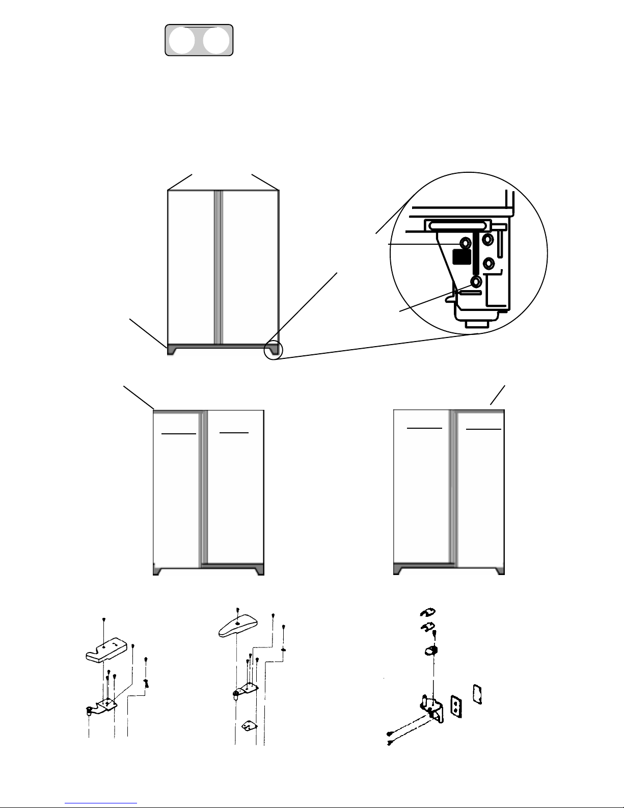
INSTALLATION CONSIDERATIONS
LEVELING THE UNIT AND ALIGNING THE DOORS
Top Hinge
Locations
▲
▲
Fig. 1
Toe Grille
Location
Door T oo
Low
Fig. 2
▲
▲
▲
▲
Rear Roller
Adjustment
Screw
Front Roller
Adjustment
Screw
Fig. 3
▲
▲
▲
▲
Door T oo
▲
Low
Hinge
Cover
Top
Hinge
Fig. 4
Shim
Shim
Shim
Door Closer
Bottom
Hinge
3
Shim
Shim
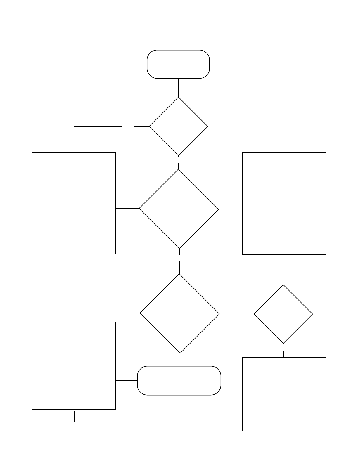
ALIGNMENT AND LEVELING PROCEDURES FLOW CHART
Slide Unit
into
Final Location.
▲
Is
NO
Unit
Stable?
▲
1. Remove toe grille by
pulling forward at
each end.
2. Turn roller adjustment screw(s) clockwise until unit is
firmly on all
roller(s). (
3. If unit is not stable
due to uneven flooring, use shims under
rear roller(s).
Fig. 6
)
▲
1. Remove top hinge
cover. Loosen top
hinge screws. (
2. Adjust both doors so
tops are aligned and
gap is consistent
from top to bottom.
3. Tighten top hinge
screws and replace
the covers.
Fig. 9
▲
▲
YES
▲
Are Tops of Doors
Aligned with Each
Other?
(Fig. 7)
YES
NO
1. Remove toe grille by
pulling forward at
each end.
2. Turn roller adjustment screw for the
▲
door that is lower
clockwise.
3. Open and close both
doors to confirm
doors are aligned.
4. Repeat until doors
are aligned.
▲
▲
Is Center Gap
NO
)
▲
Consistent from
Top to
Bottom?
(
Fig. 8
)
YES
▲
Replace T oe Grille.
▲
YES
1. Turn roller adjustment screw(s) counterclockwise until
unit is firmly on all
rollers.
2. If unit is not stable
due to uneven flooring, use shims under
rear rollers.
Is
Unit
Stable?
NO
▲
4
>
>
View Section 3 of the Video Tape
SECTION 3
THEORY OF OPERATIONTHEORY OF OPERATION
THEORY OF OPERATION
THEORY OF OPERATIONTHEORY OF OPERATION
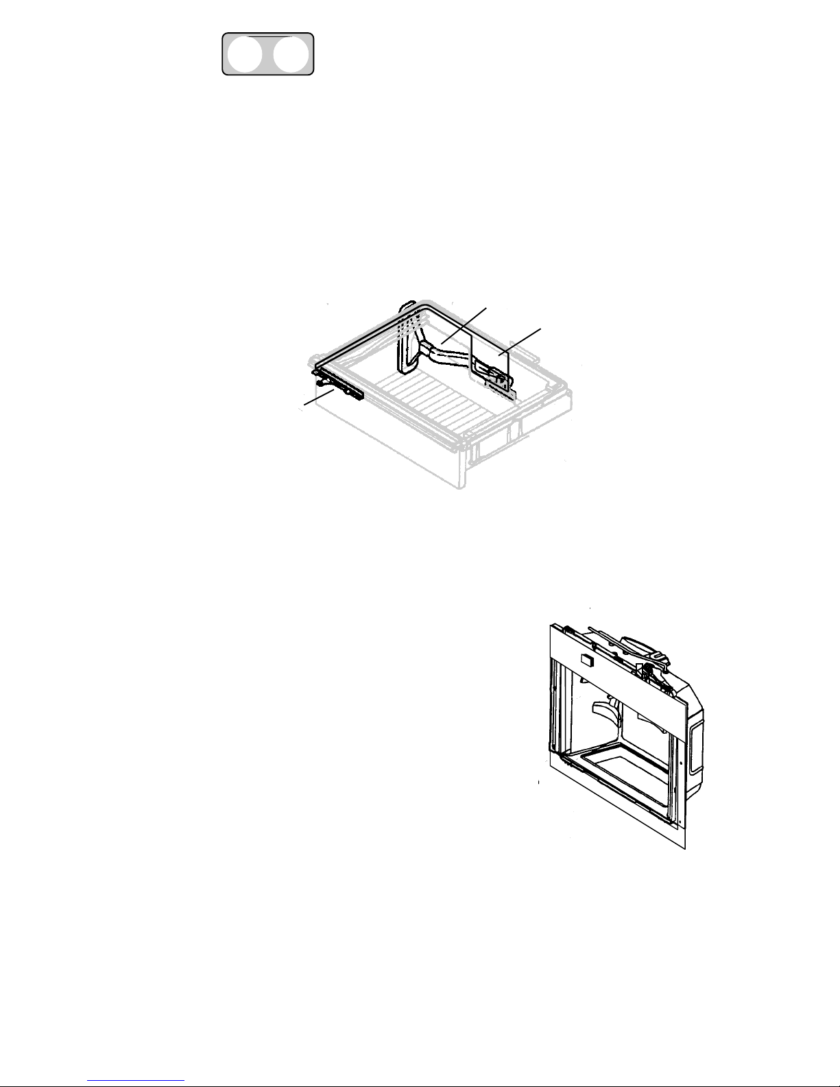
TEMPERATURE CONTROLLED MEAT LOCKER
The 26" deep side-by-side refrigerator/freezer is equipped with a chilled meat locker which will keep
the contents of the drawer approximately 5°F colder than the rest of the refrigerator section.
A slide on the front of the drawer operates a damper which directly controls the amount of freezer air
drawn into the drawer through an air duct.
AIR
DUCT
(Fig. 5)
▲
DAMPER
▲
▲
Fig. 5
SLIDE
CONTROL
ICE AND WATER DISPENSER
For ice and water dispensing, a plumbing connection must be made between the household water
supply and the dual solenoid valve mounted on the rear cabinet rail.
Ice dispensing operates as follows:
1. The automatic ice maker is mounted on the
back wall of the freezer liner. Water automatically
fills the mold, freezes into ice and dumps ice into the
the storage bin.
2. When the storage bin is full, a shut-off arm prevents
additional ice production until ice has been removed,
which lowers the shut-off arm. The storage bin will hold
approximately 8 pounds of ice. A motor driven helix is
mounted near the bottom of the storage bin.
When energized, the helix moves the ice to the front of
the storage bin where ice is directed into a lift wheel
mechanism.
3. In cube mode, the helix turns ice lift wheel counter-clockwise.
Ice bypasses the crusher blades and is dispensed into a glass.
4. In crushed mode, the helix turns clockwise forcing the ice into the crusher blades. Crushed ice
pieces will vary in size and shape.
5. Keep bits of ice from being sprayed beyond glass by placing a glass with a large opening close to
the ice chute.
(Fig. 8)
(Fig. 7)
Fig. 6
5
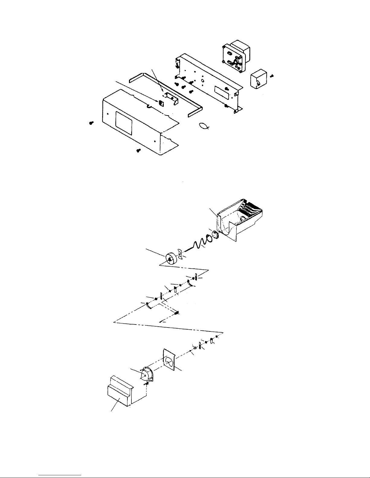
A UGER MOTOR
ASSEMBLY
LOCKING NUT
AUGER MOTOR
COVER
AUGER MOTOR
DRIVER
CAPACITOR
AUGER MOTOR
SUPPORT
Fig. 7
ICE BUCKET
ASSEMBLY
STEPPED WASHER
STATIC BLADE
BLADE COVER
CRUSHED ICE LIFT
WHEEL
STEPPED WASHER
WAVED WASHERS
WAVED WASHER
STEPPED WASHER
ICE BUCKET
HELIX CAP
ICE AGITATOR
CRUSHED ICE BAR
ROTATING BLADE
STATIC BLADE
ICE DAMPER
ROTATING BLADE
BLADE ANCHOR
ROLL PIN
WAVED WASHER
ICE DAMPER
ROTATING BLADE
LOCKING NUT
ICE CRUSHER FRONT
CRUSHED ICE BUCKET
FRONT
Fig. 8
6

6. Dispense ice by holding glass against ice lever ar m. The mechanically operated ice chute door
opens, and the motor driven helix is energized and ice is automatically dispensed into glass.
When glass is withdrawn, a delay mechanism slowly closes the ice chute door.
! WARNING
▲
To avoid risk of personal Injury or property damage, refrig erator must be
unplugged and ice storage bin must be removed before attempting to service
dispenser system. Never put fing ers, hands, or foreign objects Into Ice dispenser
opening while attempting to manually clear stalls or jams. Never use sharp
objects to break Ice. In case of stall or jam in cube or crushed mode, dispense in
opposite mode several times. There may be a delay when switching between
cube and crushed ice. This is normal. It takes a few seconds for cubes to be
moved from storage bin.
7. Sometimes a mound of “snow” will form on the door and/or ice chute. This condition is normal and
usually occurs with the repeated dispensing of crushed ice. “Snow” will eventually evaporate or
moisture can be wiped dry.
8. If the dispenser bar is held for long periods, the dispenser motor shuts off automatically after 2 to
3 minutes to prev ent ov erload. The motor resets automatically after 3 minutes and ice dispensing
can continue.
9. Use only ice from internal automatic ice maker. Do not add purchased ice cubes or cubes made
in any other manner. Dispenser operates only with cubes of proper size and shape.
10. Allow 12 hours after installation before first harvest of ice. Time required depends on freezer
temperature and amounts of food in freezer and refrigerator compartments.
11. The storage bin fills in three to four days depending on frequency of use. Two to 4 pounds of ice
will be made in a 24-hour period with a 0°F to 2°F freezer food temperature.
12. To temporarily meet demands for increased ice production, turn freezer control to colder setting.
Return freezer control to normal setting as soon as possible.
Water dispenser operates as f ollows:
1. The reservoir is located in the refrigerator section directly behind the crisper drawers. The reservoir
inlet tube comes from a solenoid valve mounted on the rear cabinet rail.
2. The reservoir holds approximately 40 ounces of water.
3. The outlet tube exits through the refrigerator floor and travels through a conduit foamed into the
cabinet bottom to a location just short of the freezer door bottom hinge. 5/16 inch tube is reduced
to 1/4 inch by means of a coupling. The tube enters the freezer door through the center of the
hinge pin and runs up the left flange of the door and crosses over the top of the cavity behind the
water dispensing lever.
following glasses, since the water tube leading to the dispenser from the water reser voir is not
refrigerated.
(Fig. 9)
NOTE: The first glass of water will be somewhat warmer than
4. The reservoir is filled by holding a glass against water the lever arm until water flo ws into a glass .
5. If household plumbing has been disturbed, thoroughly flush the water system. This will help
remove foreign materials in the water and also flush plumbing in refrigerator.
7
 Loading...