

Whirlpool E3F50HD045OV, E1F6US015V, E6119L045DV, E6140L045DV, E6140R045D Installation And Use Manual
...
Whi l ol
Water Heaters
Residential Electric
Water Heater
lnstallati n
lnst ct" n
Use Care Gu"
To obtain technical, warranty or service assistance during or
after the installation of this water heater, call toll free 1-877-
817-6750
When calling for assistance, please have the following
information ready:
1. Model number
2. 7 Digit product number
3. Serial number
4. Date of installation
5. Place of Purchase
TM
Table Of Contents PAGE
Water Heater Safety ..................................................................... 2
Installing Your Electric Water Heater ........................................ 3-8
Unpacking Instructions ................................................ 3
Location Requirements ................................................ 4
Electrical Requirements ............................................... 5
Water System Piping ................................................... 6
Installation Checklist .................................................... 8
Operating Your Water Heater ....................................................... 9-11
Water Temperature Regulation .................................... 9
Adjusting the Thermostat ..................................................... 1 0
Operational Conditions ........................................................ 1 1
Maintenance of Your Water Heater ................................................. 12-1 3
Trouble Shooting Chart ............................................................. 14
Repair Parts Illustration ............................................................. 1 5
Thermostat Wiring Chart and Diagram ..................................... 1 6
6510194
JULY 2000
Your safety and the safety of others are very important.
We have provided many important safety messages in this manual and on your appliance. Always read and obey all
safety messages.
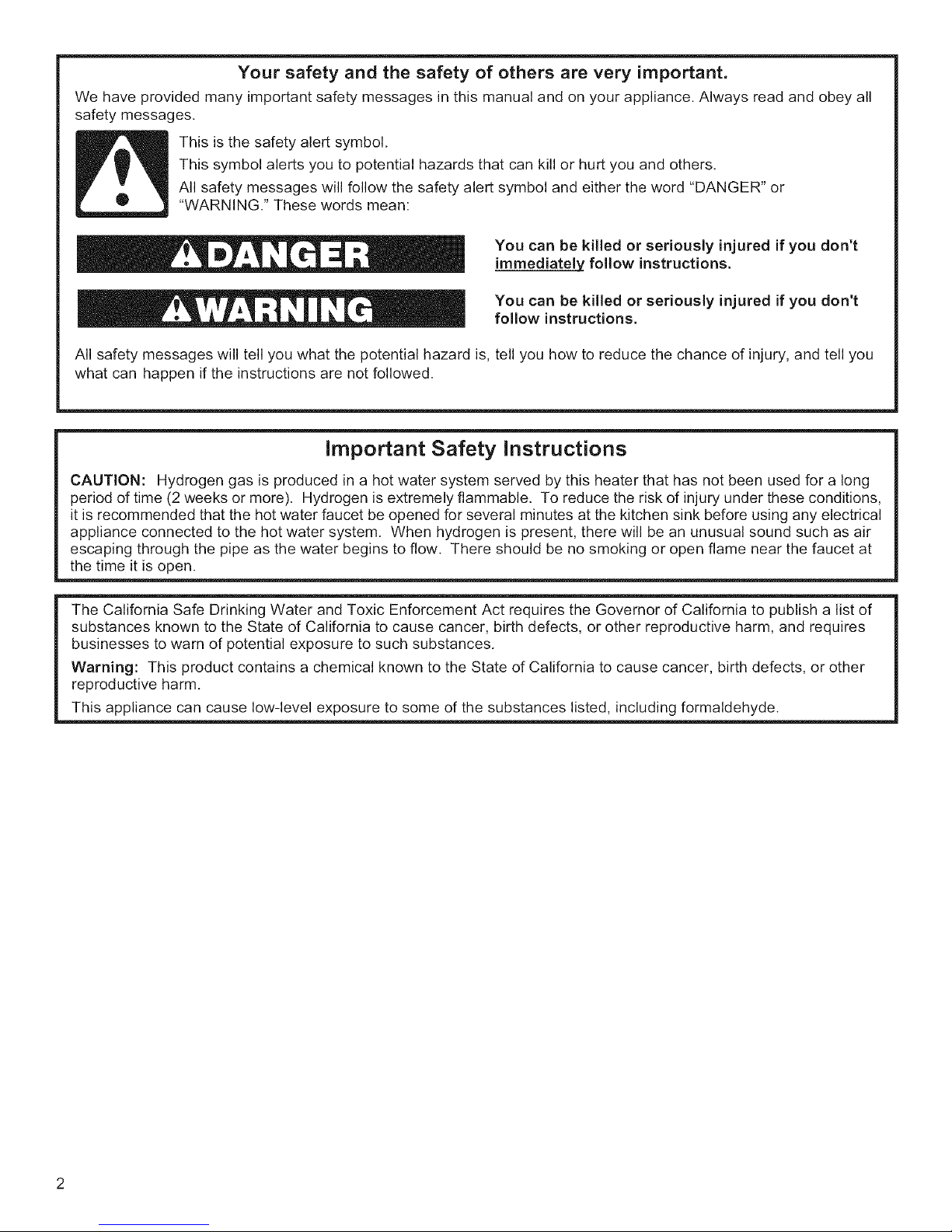
This is the safety alert symbol.
This symbol alerts you to potential hazards that can kill or hurt you and others.
All safety messages will follow the safety alert symbol and either the word "DANGER" or
"WARNING." These words mean:
You can be killed or seriously injured if you don't
immediately follow instructions.
You can be killed or seriously injured if you don't
follow instructions.
All safety messages will tell you what the potential hazard is, tell you how to reduce the chance of injury, and tell you
what can happen if the instructions are not followed.
Important Safety Instructions
CAUTION: Hydrogen gas is produced in a hot water system served by this heater that has not been used for a long
period of time (2 weeks or more). Hydrogen is extremely flammable. To reduce the risk of injury under these conditions,
it is recommended that the hot water faucet be opened for several minutes at the kitchen sink before using any electrical
appliance connected to the hot water system. When hydrogen is present, there will be an unusual sound such as air
escaping through the pipe as the water begins to flow. There should be no smoking or open flame near the faucet at
the time it is open.
The California Safe Drinking Water and Toxic Enforcement Act requires the Governor of California to publish a list of
substances known to the State of California to cause cancer, birth defects, or other reproductive harm, and requires
businesses to warn of potential exposure to such substances.
Warning: This product contains a chemical known to the State of California to cause cancer, birth defects, or other
reproductive harm.
This appliance can cause low-level exposure to some of the substances listed, including formaldehyde.
INSTALLING YOUR WATER HEATER
Consumer information
This water heater should be installed in accordance with
the local code authority having jurisdiction, the power
company or electric utility, and this installation manual.
In the absence of local code requirements, follow the
regulations set forth in the latest edition of The National
Electric Code, NFPA 70. This is available from the
following:
National Fire Protection Agency
1 Batterymarch Park
Quincy, MA 02269
American National Standards Institute
1430 Broadway
New York, NY 10018
Check your phone listings for the local authorities having
jurisdiction over your installation.
Consumer Responsibilities
This manual has been prepared to acquaint you with the
installation, operation and maintenance of your electric
water heater and to provide important safety information
in these areas.
We urge you to read all of the instructions thoroughly
before attempting the installation or operation of this
water heater. This manual should be kept for future
reference.
The manufacturer of this water heater will not be liable
for any damages caused by failure to comply with the
installation and operating instructions outlined in this
manual.
If you lack the necessary skills required to properly install
this water heater or you have difficulty following the
directions, you should not proceed but have a qualified
person perform the installation of this water heater.
A data plate identifying your water heater can be found
adjacent to the element door. When referring to your
water heater always have the information listed on the
data plate readily available.
Retain your original receipt as proof of purchase.
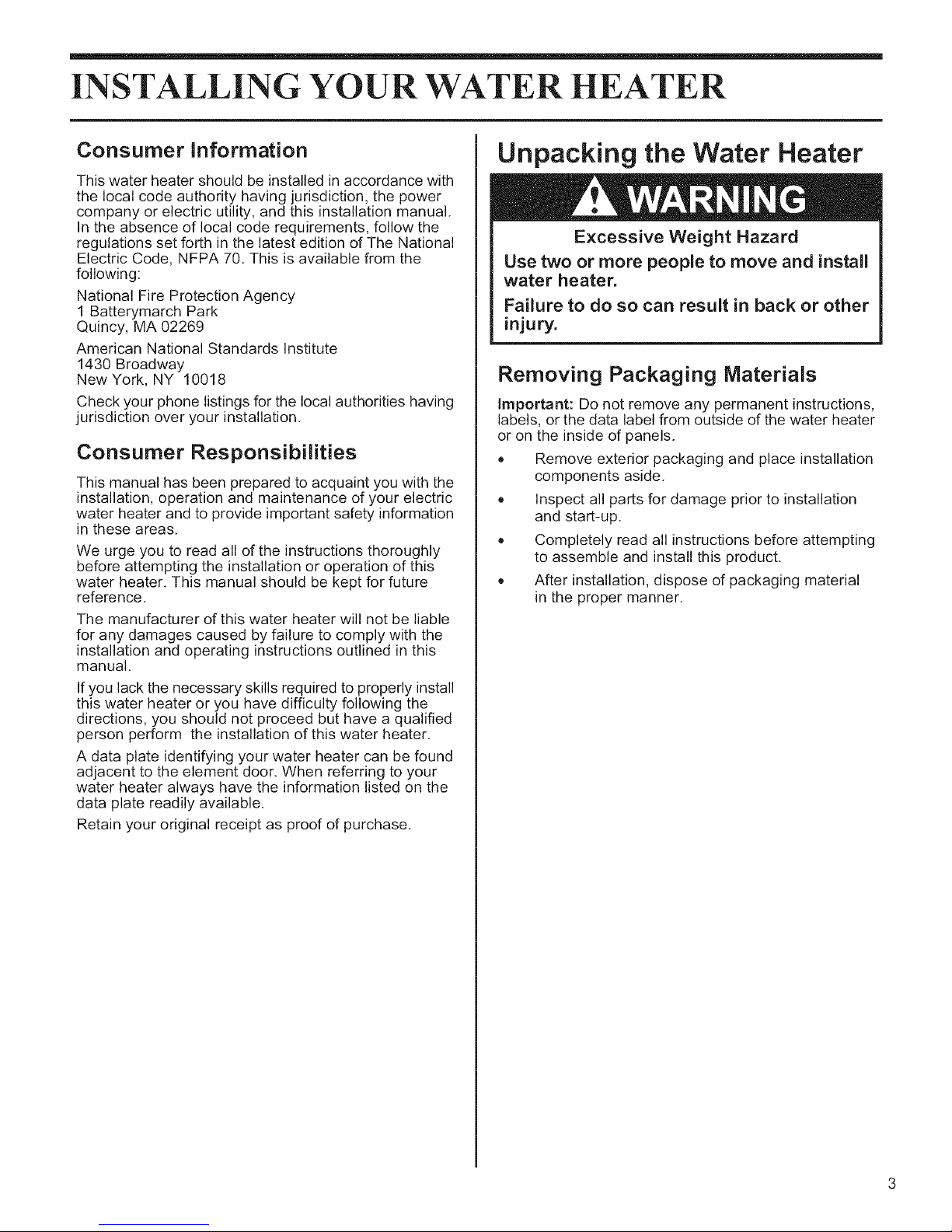
Unpacking the Water Heater
Excessive Weight Hazard
Use two or more people to move and install
water heater.
Failure to do so can result in back or other
injury.
Removing Packaging Materials
Important: Do not remove any permanent instructions,
labels, or the data label from outside of the water heater
or on the inside of panels.
Remove exterior packaging and place installation
components aside.
Inspect all parts for damage prior to installation
and start-up.
Completely read all instructions before attempting
to assemble and install this product.
After installation, dispose of packaging material
in the proper manner.
Location Requirements
Site location
Select a location near the center of the water piping
system. It must be installed indoors and in a vertical
position on a level surface.
The water heater should be located in an area not subject
to freezing temperatures. Water heaters located in
unconditioned spaces (i.e., attics, basements, etc.) May
require the water piping and drain piping to be insulated
to protect against freezing. The drain and controls must
be easily accessible for operation and service.
Do not use this water heater in conjunction with a spa
or hot tub.
Note: Local codes and requirements in your area may
require the installation of your water heater be
accomplished ina way that the bottom element is elevated
from the floor at least 18 inches.
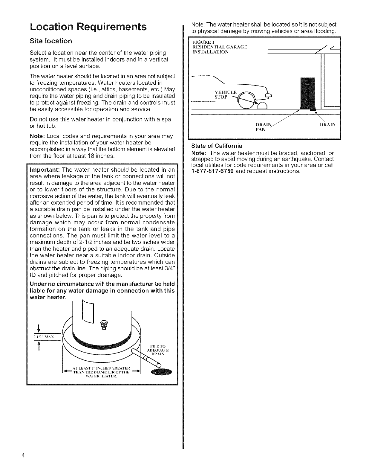
Important: The water heater should be located in an
area where leakage of the tank or connections will not
result in damage to the area adjacent to the water heater
or to lower floors of the structure. Due to the normal
corrosive action of the water, the tank will eventually leak
after an extended period of time. It is recommended that
a suitable drain pan be installed under the water heater
as shown below. This pan is to protect the property from
damage which may occur from normal condensate
formation on the tank or leaks in the tank and pipe
connections. The pan must limit the water level to a
maximum depth of 2-1/2 inches and be two inches wider
than the heater and piped to an adequate drain. Locate
the water heater near a suitable indoor drain. Outside
drains are subject to freezing temperatures which can
obstruct the drain line. The piping should be at least 3/4"
ID and pitched for proper drainage.
Under no circumstance will the manufacturer be held
liable for any water damage in connection with this
water heater.
Note: The water heater shall be located so it is not subject
to physical damage by moving vehicles or area flooding.
FIG URE 1
RESIDENTIAL GARAGE
INS'IS_LLATION
VEHICLE
STOP
DRAIN_ DRAIN
PAN
State of California
Note: The water heater must be braced, anchored, or
strapped to avoid moving during an earthquake. Contact
local utilities for code requirements in your area or call
1-877-817-6750 and request instructions.
2 1/2" MAX
t
TITAN TIlE DIAMETER OF TItE
_\_A.TER HEATER.
PIPE TO
ADEQUATE
DRAIN
A
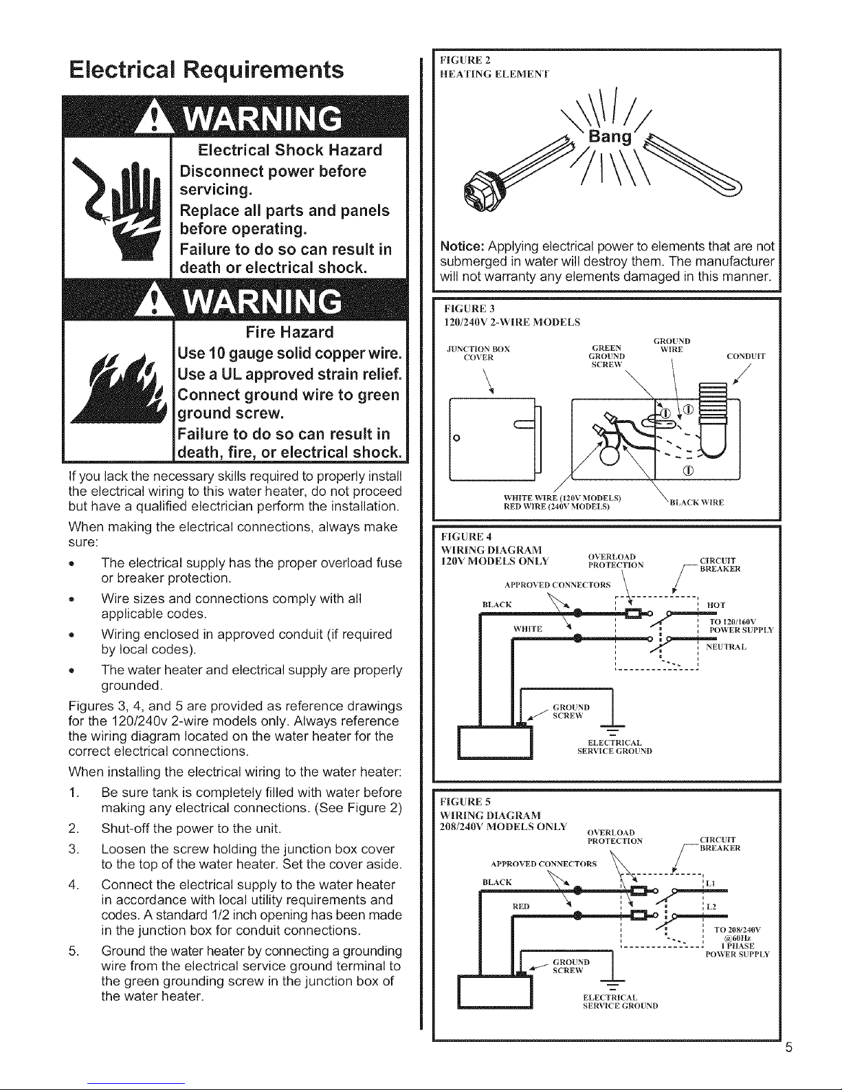
Electrical Requirements
FIGURE 2
HEATING ELEMENT
, /
Electrical Shock Hazard
Disconnect power before
servicing.
Replace all parts and panels
before operating.
Failure to do so can result in
death or electrical shock.
Fire Hazard
Use 10 gauge solid copper wire.
Use a UL approved strain relief.
Connect ground wire to green
ground screw.
Failure to do so can result in
death, fire, or electrical shock.
If you lack the necessary skills required to properly install
the electrical wiring to this water heater, do not proceed
but have a qualified electrician perform the installation.
When making the electrical connections, always make
sure:
The electrical supply has the proper overload fuse
or breaker protection.
Wire sizes and connections comply with all
applicable codes.
Wiring enclosed in approved conduit (if required
by local codes).
The water heater and electrical supply are properly
grounded.
Figures 3, 4, and 5 are provided as reference drawings
for the 120!240v 2-wire models only. Always reference
the wiring diagram located on the water heater for the
correct electrical connections.
When installing the electrical wiring to the water heater:
1. Be sure tank is completely filled with water before
making any electrical connections. (See Figure 2)
2. Shut-off the power to the unit.
3. Loosen the screw holding the junction box cover
to the top of the water heater. Set the cover aside.
4. Connect the electrical supply to the water heater
in accordance with local utility requirements and
codes. A standard 1/2 inch opening has been made
in the junction box for conduit connections.
5. Ground the water heater by connecting a grounding
wire from the electrical service ground terminal to
the green grounding screw in the junction box of
the water heater.
Bang
I
Notice: Applying electrical power to elements that are not
submerged in water will destroy them. The manufacturer
will not warranty any elements damaged in this manner.
FIGURE 3
120/240V 2-WIR, E MODELS
JUNCTION BOX GREEN
COVER GROUND
SCREW
GROUND
WIRE
CONSULT
Io
WlltTE WIRE (120V MODELS)
RED WIRE (240V MODELS)
FIGURE 4
WIRING DIAG RAM
120V MODELS ONLY OVERLOAD CIRCUIT
APPROVED CONNECTORS _ # BREAKER
PROTECTION
B_,ACK _'_ :-# ..... :.OT
__o 12o/16ov
\_ HtTE "_ _ _ m _ POWER SUPPLY
I : _ i NEUTRAL
GROUND
ELECTRICAL
SERVICE GROUND
FIGURE 5
WIRING DIAGRAM
208/240V MODELS ONLY
APPROVED CONNECTORS _ S BREAKER
__BLACK , ',L1
| | ', "-.. : c.6om
OVERLOAD
PROTECTION CIRCUIT
-- P()_R SUPP[X
GROUND
Z-...........
ELECTRICAL
SERVICE GROUND
XRLACK WIRE
i__
:......... __L____J
........ I
208 240V
 Loading...